![]() USER MANUAL
USER MANUAL
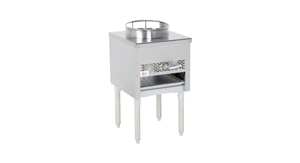
Wok Range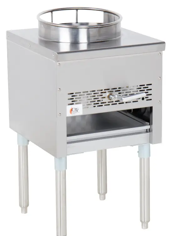
![]() MODEL: 351CPGWOK(LP/NG)
MODEL: 351CPGWOK(LP/NG)
05/2018
This users manual contains information and guidelines collected from years of industry experience. For optimal safety
have them read this manual carefully before startup. Cooking Performance Group declines any responsibility in the event users does not follow the instructions or guidelines stated here. We have the full authority to reserve the further technical changes of the unit, in the scope of further performance improvement characteristic development.
Should you have any questions about the proper use of this product, please contact Cooking Performance Group using the information listed on the back page of this manual.
WARNING!
- Please contact Cooking Performance Group for any adjustment or maintenance. Service must be performed by an authorized technician.
- and substances. Do not store or use any such items in the vicinity of this unit.
- (including children), nor should it be used by those with physiological, perceptual, or mental disabilities without proper supervision.
- Keep children away from the appliance for their safety.
- Always keep this manual accessible. When transferring possession of the appliance to a third party, the manual must also be handed over. All users must operate the unit in compliance with this manual.
- Any nearby walls, surfaces, kitchen supplies, etc. should be non-combustible and heat-resistant. Please pay
SHIPPING DAMAGE CLAIM PROCEDURE
The equipment is inspected & crated carefully by skilled personnel before leaving our factory. The transportation company assumes full responsibility for safe delivery upon acceptance of this equipment. If a shipment arrives damaged: 1. Visible loss or damage: Note on freight bill or express delivery and have signed by person making delivery. 2. File claim for damages immediately: Regardless of the extent of damages. 3. Concealed loss or damage: If damage is noticed after unpacking, notify the transportation company
INSTALLATION INSTRUCTIONS
- Installation of all equipment should be performed by qualified, certified, and authorized personnel who are familiar and experienced with local installation codes.
- Before installation, please read the instructions completely and carefully.
- Do not remove permanently affixed labels, warnings, or plates from the product.
- Please observe all local and national codes and ordinances.
- Installation must conform with local codes, or in the absence of local codes, the National Fuel Gas Code, ANSI Z223.1 (latest edition). In Canada, installation should conform to installation codes for gas-burning appliances and equipment standard CAN/CGA-B149.1 or the propane installation code, CAN/CGA-B149.2, as applicable.
- Electrical wiring to the appliance must be electrically grounded in accordance with local codes or in the absence of local codes with the National Electrical Code ANSI/NFPA 70, or the Canadian Electrical Code, CSA C22.2, as applicable.
- A manual gas shut-off valve must be installed in the gas supply line ahead of the appliance and gas pressure regulator for safety and ease in servicing.
- The gas pressure regulator supplied must be installed on the appliance prior to connecting the equipment to the gas line. Failure to install a regulator could be potentially hazardous and will void the appliance warranty.
- The appliance and its individual shut off valve must be disconnected from the gas supply piping system during any pressure testing of that system at test pressures in excess of 1/2 psi (3.45kpa).
- The appliance must be isolated from the gas supply piping system, by closing its individual manual shut off valve during any pressure testing of the gas supply piping system at test pressures equal to or less than V2 psi (3.45kpa).
OPERATING INSTRUCTIONS
- The operation of this equipment must be performed by qualified or authorized personnel who have read and are familiar with the functions of the equipment.
MAINTENANCE
- To perform maintenance and repairs of the appliance, please contact the factory, factory representative, or the nearest authorized local service company to get proper repairs.
RATING PLATE
- Information on this plate includes the model, serial number, BTU/hour input of the burners, operating gas pressure in inches WC, and whether the appliance is fitted for natural gas or liquid propane. When communicating with the factory about a unit or requesting special parts or information, rating plate data is essential for proper identification.
COOKING PERFORMANCE GROUP COOKING APPLIANCES MUST BE CONNECTED ONLY TO THE TYPE OF GAS IDENTIFIED ON THE RATING PLATE 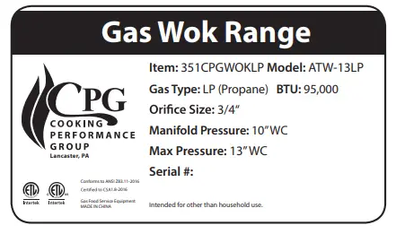
CLEARANCES
- The appliance area must be kept free and clear of all combustible materials and placed horizontally on a non-skid surface.
| CPG MODEL | Non-Combustible | Combustible | ||
| Rear | Sides | Rear | Sides | |
| CPGWOKLP – Wok Range | 0″ | 0″ | 17″ | 17″ |
| CPGWOKNG – Wok Range | 0″ | 0″ | 17″ | 17″ |
- The area in front of, around, and above the appliance must be kept clear to avoid any obstruction of the flow of combustion and ventilation air.
- Adequate clearance must be maintained around the appliance for easy servicing.
- Provisions should be made for any commercial, heavy-duty cooking appliance to have it its exhaust combustion waste products released to the outside of the building. The usual practice is to place the appliance under an exhaust hood, which should be constructed in accordance with local codes. Strong exhaust fans in this hood or in the overall air conditioning system can produce a slight vacuum in the room and/or cause air drafts, either of which can interfere with the pilot or burner performance and could be difficult to diagnose. Air movement should be checked during installation. Air openings or baffles may have to be provided in the room if pilot or burner outrage problem persists.
GAS CONNECTION
- The gas supply (service) line must be the same size or greater than the inlet line of the appliance. Cooking Performance Group appliances use a 3/4″ NPT inlet. Sealant on all pipe joints must be resistive to liquid propane or natural gas. This range uses NG32 and LP49 connections for gas nozzles.
MANUAL SHUT OFF VALVE
- This installer-supplied valve must be in the gas service line ahead of the appliance regulator in the gas stream and in a position accessible in the event of an emergency.
PRESSURE REGULATOR
- Commercial cooking equipment must have a pressure regulator on the incoming service line for safe and efficient operation, since service pressures may fluctuate on local demand. A pressure regulator is packed inside every Cooking Performance Group appliance.
- FAILURE TO INSTALL THE PRESSURE REGULATOR WILL VOID THE APPLIANCE WARRANTY.
- The regulators supplied along with Cooking Performance Group appliances, will have 3/4″ inlet/outlet openings and are adjusted at the factory for 4″ WC (natural gas) or 10″ WC (liquid propane gas) depending on the customer’s ordering instructions.
- Prior to connecting the regulator, check the incoming line pressure, as these regulators can only withstand a maximum pressure of 1/2″ psi (14″ WC). If the line pressure is beyond this limit, a step-down regulator will be required.
- The arrow shown on the bottom of the regulator body shows the gas flow direction, it should point downstream to the appliance. The red air vent cap on the top is part of the regulator and should not be removed.
- Any adjustments to the regulator should be made only by qualified service personnel with the proper equipment.
CONNECTIONS
Please check installer-supplied intake pipes visually and/or blow them with compressed air to clear any dirt particles, threading chips or any other foreign matter before installing a service line. When gas pressure is applied, these particles could clog orifices. All connections must be sealed with a joint compound suitable for LP and natural gas, and all connections must be tested with a soapy water solution before lighting any pilots.
INITIAL PILOT LIGHTING
![]() CAUTION: When lighting pilots and checking for leaks, do not stand with your face close to the combustion chamber.
CAUTION: When lighting pilots and checking for leaks, do not stand with your face close to the combustion chamber. ![]()
- All Cooking Performance Group appliances are adjusted and tested before leaving the factory, effectively matching them to sea-level conditions. Adjustments and calibrations to assure proper operation may be necessary on installation to meet local conditions or adapt to low gas characteristics; correct possible problems caused by rough handling or vibration during shipment and are to be performed only by qualified service personnel. These adjustments are the responsibility of the customer and/or dealer and are not covered by our warranty. Check all gas connections for leaks with a soapy water solution before lighting any pilots.
LIGHTING & SHUTDOWN
- Tum the control valve to position 0, or OFF.
- Make sure all knobs are in a closed state.
- Wait for 5 minutes. Tum pilot valve(s) by adjusting the screw counterclockwise, then light standing pilot and adjust flame 1/4 inch high.
- If not lit immediately, wait 1 minute for existing gas in the pipe to disperse, and try again after 1 minute.
- Tum ON gas valve(s) to light the main burner.
- For complete shutdown, shut OFF the gas valve(s) and tum pilot valve(s) by adjusting the screw clockwise to shut off gas to the pilot(s).
- Wait 5 minutes before next use.
ENERGY CONVERSION
- Turn off the range, remove all objects, and disconnect energy sources.
- Remove control panel, cooking grates, pilot light head, and burner
- Remove the main energy nozzle and replacement with another gas source by screwing it in clockwise.
- Reinstall burner, pilot light head, cooking grates, and control panel in proper order.
- Have authorized technicians to adjust input appropriately.
ADJUST AIR INPUT
- Remove the control panel and unscrew the damper solid screw
- Rotate damper to the desired opening, observe flame, and adjust to an appropriate degree
- Tighten screw damper solid screw to ensure the equipment will not get loose in transportation
- Reinstall the control panel.
CLEANING & MAINTENANCE
Any equipment works better and lasts longer when maintained properly. Cooking equipment is no exception.Your Cooking Performance Group appliance must be cleaned on a daily basis.
DAILY MAINTENANCE
BURNERS
- Turn off the range, remove all objects, and disconnect energy source.
- Remove all top grates.
- Liftoff the burner heads by raising the head slightly, sliding to the rear of the range, and lifting upwards.
- Wash off the above in hot soapy water.
- Re-install burner parts in reverse order.
- Wipe body, panel, and control knobs with mild detergent
- Pull catch tray from the front body, wipe away residue, and clean with mild detergent.
STAINLESS STEEL
- All stainless steel body parts should be wiped regularly with hot soapy water during the day, and with a liquid cleaner designed for this material at the end of each day.
- DO NOT USE steel wool, abrasive cloths, or powders to clean stainless surfaces.
- If it is necessary to scrape stainless steel to remove encrusted materials, soak in hot water to loosen the material, then use a wood or nylon scraper. DO NOT USE a metal knife, spatula, or any other metal tool to scrape stainless steel. Scratches are nearly impossible to remove.
DAILY MAINTENANCE
- Ensure your Cooking Performance Group range is checked by a qualified technician once a year for efficient operation of the appliance.
CONTACT THE FACTORY, FACTORY REPRESENTATIVE, OR A LOCAL SERVICE COMPANY TO PERFORM ALL MAINTENANCE AND SERVICE REPAIRS.
TROUBLESHOOTING
| ISSUE | POSSIBLE CAUSES | REMEDIES |
| Pilot not lighting | Insufficient gas pressure in the pipe | Contact local gas supply department |
| Nozzle occlusion | Dredge nozzle | |
| The pilot ignited, but not the main burner | Insufficient gas pressure in the pipe | Contact local gas supply department |
| Nozzle occlusion | Dredge nozzle | |
| Gas control valves broken | Replace control valves | |
| Low flame distance | Adjust distance | |
| Low flame | Adjust the height of the pilot light | |
| Inconsistent burning | Insufficient gas pressure in the pipe | Contact local gas supply department |
| The nozzle does not match gas requirements | Adjust nozzle diameter | |
| The flow of the connection pipe is not adequate | Increase pipe’s allowable flow | |
| The damper opening degree is too large | Adjust damper | |
| Yellow flame and/or black smoke | Incorrect gas | Change gas |
| The nozzle does not match gas requirements | Adjust nozzle diameter | |
| Not enough air to ignite | Increase damper opening degree | |
| Gas spikes and floats | Turn down valve flow |
THE PROBLEMS MENTIONED ABOVE ARE FOR REFERENCE ONLY.
IF ANY FAULT OCCURS, STOP USING THE MACHINE IMMEDIATELY AND CONTACT AN AUTHORIZED TECHNICIAN TO CHECK AND MAKE REPAIRS.
SPECIFICATIONS
| MODEL | CPGWOKLP | CPGWOKNG |
| EXTERIOR DIMENSIONS | 18″ x 20.5″ x 28″ | 18″x 20.5″x 28″ |
| PACKING DIMENSIONS | 21″x 27″x 30″ | 21″x 27″ x 30″ |
| NET WEIGHT | 125.0 Lb. | 125.0 Lb. |
| GROSS WEIGHT | 135.0 Lb. | 135.0 Lb. |
| # OF BURNERS | 1 | 1 |
| GAS TYPE | Liquid Propane | Natural Gas |
| INTAKE TUBE PRESSURE | 10″WC | 5″WC |
| BTU PER BURNER | 95,000 | 95,000 |
| BTU TOTAL | 95,000 | 95,000 |
| NOZZLE NO. | LP67 | NG 56 |
| IGNITION TYPE | Manual | Manual |
| VALVE TYPES | Pilot Light | Pilot Light |
| TEMPERATURE CONTROL | None | None |
| WOK ATTACHMENT | 13.75″ x 3.5″ | 13.75″x 3.5″ |
SPECIFICATIONS MAY VARY DEPENDING ON THE MODEL AND ARE SUBJECT TO CHANGE AT ANY TIME.
EXPLODED VIEW
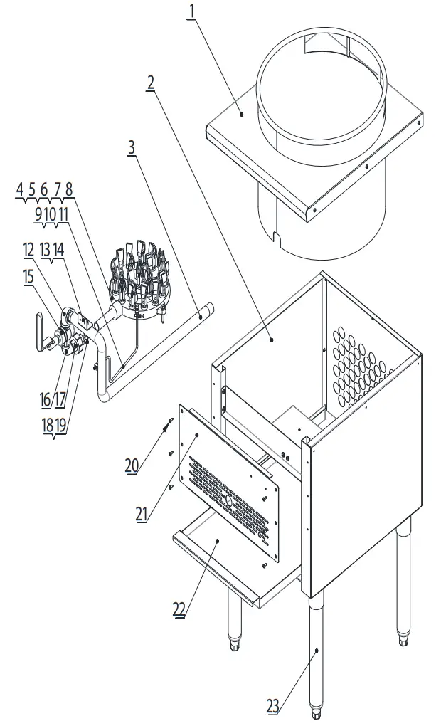
PARTS LIST
| Part Code | Our Item # | Description | QTY | |
| 1 | 21209001001 | Top plate | 1 | |
| 2 | 21209001002 | Body | 1 | |
| 3 | 301070059 | 351PWOK1 | Input pipe | 1 |
| 4 | 301081006 | Galvanized American outside six corners with P ad tapping | 2 | |
| 5 | 301060061 | Burner connection pipe | 1 | |
| 6 | 301020015 | 351PWOK11 | Duck mouth burner | 18 |
| 7 | 301040037 | 351 PWOK2 | Burner nozzle(na56) | |
| 7 | 301040038 | 351 PWOK3 | Burner nozzle(Ip67) | |
| 8 | 301020014 | Burner base | 1 | |
| 9 | 301060003 | 351PWOK4 | Pilot light head | 1 |
| 10 | 301030001 | 351PWOK5 | Pilot light valve-single unit | 1 |
| 11 | 21109001014 | 351PWOK6 | Air input pipe | 1 |
| 12 | 301050060 | Reducing elbow | 1 | |
| 13 | 301080002 | Galvanized flange face nut | 1 | |
| 14 | 21109001013 | 351PWOK7 | Intake-tube stator | 1 |
| 15 | 301030048 | Control valve (with the handle) | 1 | |
| 16 | 301050004 | Street elbow | 1 | |
| 17 | 301050002 | Union | 1 | |
| 18 | 301060002 | 351 PWOK8 | Needle type pressure joint screw arbor | 1 |
| 19 | 301060001 | 351PWOK9 | Needle type pressure joint | 1 |
| 20 | 301081030 | Nickel-plated pan-head self-drilling screw | 15 | |
| 21 | 21109001012 | Control panel | 1 | |
| 22 | 21109001011 | 351PWOK10 | Catch tray | |
| 23 | 301050059 | Support leg | 4 |
NOTES
www.CookingPerformanceGroup.com


