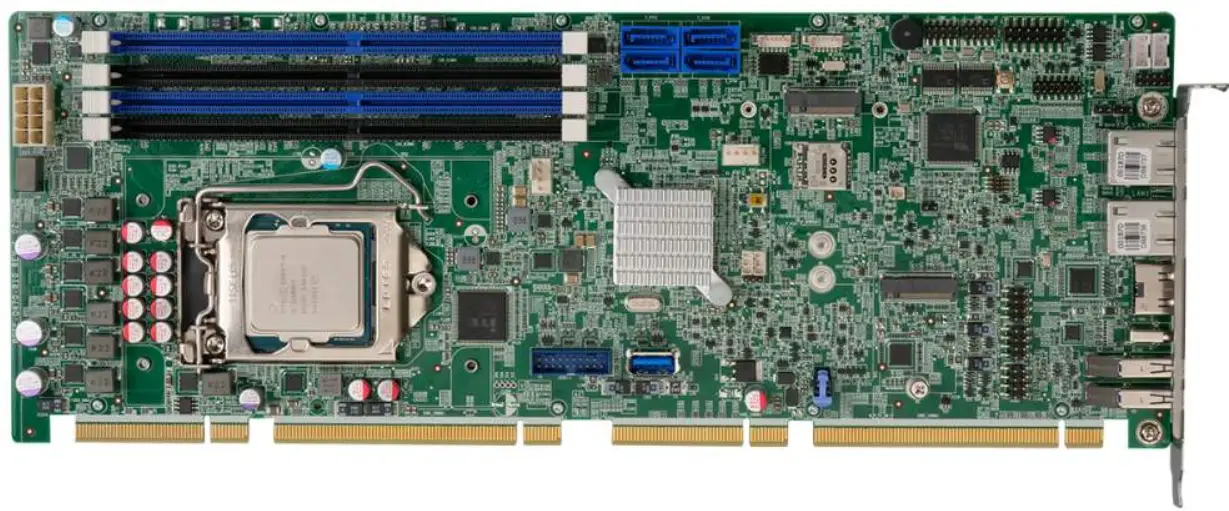
icp PCIE-Q470 Full-size PICMG 1.3 CPU Card
Package List
PCIE-Q470 package includes the following items
- 1 x PCIE-Q470 single board computer
- 1 x SATA cable
- 1 x Mini jumper pack
- 1 x QIG
Specifications
- CPU:
10th/11th Generation LGA1200 Intel® Core™ i9/i7/i5/i3, Pentium® and Celeron® processors - Chipset:
Intel® Q470 - Memory:
Four 288-pin 2933 MHz dual-channel DDR4 DIMM slots supporting up to 128 GB memory - BIOS:
AMI UEFI BIOS - Graphics Engine:
- 10th Generation CML-S: up to Intel® UHD Graphics 630, Intel® HD 9th Generation Display Engine based on 16 low power execution units supporting DX2015, OpenGL 5.X and OpenCL2.x, ES 2.0
- 11th Generation RKL-SXe: 12th Generation Graphics Architecture, Intel® UHD Graphics 750, supporting 12-bit end-to-end, AV1, VP9, HEVC 12b, HDR10, FP16
- Display Output:
1 x HDMI 1.4 (up to 4096 x 2160 @ 30 Hz) - Ethernet:
- LAN1: Intel® I225V 2.5GbE controller (Colay with I225-LM)
- LAN2: Intel® I225V 2.5GbE controller (Colay with I225-LM)
- External I/O Interface:
- 2 x USB 3.2 Gen 1 (5Gb/s) (Type-A)
- 1 x USB 3.2 Gen 2 (10Gb/s) (Type-C)
- Internal I/O Interface:
- 4 x SATA 6Gb/s (RAID 0/1/5/10 supported)
- 6 x USB 2.0 (2×4 pin, p=2.54)
- 2 x USB 3.2 Gen 1 (5Gb/s) (2×10 pin, p=2.0)
- 1 x USB 3.2 Gen 1 (Type-A, 180°)
- 2 x RS-232 (2×5 pin, p=2.0)
- 2 x RS-422/485 (1×4 pin, p=2.0)
- Audio:
1 x IAUDIO connector supporting IEI AC-KIT-888S audio module (2×5 pin, p=2.0) - Front Panel:
1 x Front panel (2×7 pin, p=2.54; power LED, HDD LED, power button, reset button, speaker) - LAN LED:
2 x LAN LED (1×2 pin, p=2.54) - Expansions:
- 1 x PCIe x16 signal via golden finger (supporting x16, or x8 + x8, or x4 + x4 + x8)
- 4 x PCIe x1 signal from PCH via golden finger (supporting one x4, or four x1)
- 4 x PCI signal via golden finger
- 1 x M.2 2230 A Key (PCIe x2 & USB 2.0)
- 1 x M.2 3042/3052 B Key w/ SIM holder (PCIe Gen3 x2)
- 1 x M.2 2280/2242 M Key on solder side (PCIe x4)
- Digital I/O:
1 x 12-bit digital I/O (2×7 pin, p=2.0) - SM Bus:
1 x SM Bus (1×4 pin, p=1.25) - I2C:
1 x I2C (1×4 pin, p=1.25) - Fan Connector:
1 x CPU fan connector (1×4 pin)
1 x System fan connector (1×4 pin) - Chassis Intrusion:
1 x Chassis intrusion connector (1×2 pin, p=2.54) - TPM:
Intel® PTT (TPM 2.0) - Power Supply:
- ATX/AT power supply
- Support AT/ATX mode
- ErP/EuP compliant
- Power Consumption:
- [email protected], [email protected], [email protected]
- (Intel® Core™ i9-11900K CPU with 4 GB 3200 MHz DDR4 memory)
- Watchdog Timer:
Software programmable support 1–255 sec. system reset - Operation Temperature: 0°C – 60°C
- Storage Temperature: -30°C – 70°C
- Operation Humidity: 5% – 95%, non-condensing
- Dimensions: 338 mm x 126 mm
- Weight: GW:1000 g / NW:500 g
- Safety: CE/FCC compliant
All the drivers and utility for the PCIE-Q470 are available on IEI Resource Download Center. Type PCIE-Q470 and press Enter to find all the relevant software, utilities, and documentation. To install software from the downloaded ISO file, mount the file as a virtual drive to view its content.
IEI Resource Download Center
https://download.ieiworld.com
Ordering Information
- PCIE-Q470-R10:
Full-size PICMG 1.3 CPU card supports 10th/11th Gen. LGA1200 Intel® Core™ i9/i7/i5/i3, Pentium® and Celeron® processors, Intel® Q470, DDR4 DIMM, HDMI, dual Intel® 2.5GbE, USB 3.2 Gen 2, SATA 6Gb/s, M.2, iAudio and RoHS - CB-USB02-RS:
Dual port USB cable with bracket, 300mm, p=2.54 - 32102-000100-200-RS:
SATA power cable, MOLEX 8981-4M to SATA15P, 150mm - 32205-002700-200-RS:
RS-232/422/485 cable, 200mm, p=2.0 - AC-KIT-888S-R10:
Realtek ALC888S 7.1 Channel HD Audio peripheral board, RoHS - CF-1150SA-R10
Special cooler kit for LGA1150, high-performance compatible, 95W - CF-1150SB-R11
Special cooler kit for LGA1150, high-performance compatible, 65W - CF-1150SC-R20
Special cooler kit for LGA1150, 1U chassis compatible, 65W - CF-1150SE-R11
Special cooler kit for LGA1150, high-performance compatible, 95W
Jumpers Setting and Connectors
| LABEL | FUNCTION |
| J_ATX_AT1 | AT/ATX power mode setting |
| SW_BIOS1_1 | BIOS selection switch |
| J_CMOS1 | Clear CMOS jumper |
| J_FLASH1 | Flash descriptor security override jumper |
| CPU12V1 | ATX CPU 12V power connector |
| J_AUDIO1 | Audio connector |
| BAT1 | RTC battery connector |
| CHASSIS1 | Chassis intrusion connector |
| CHA_DIMM0, CHA_DIMM1 CHB_DIMM0, CHB_DIMM1 | DDR4 DIMM slots |
| DIO1 | Digital I/O connector |
| DBG_SPI1 | EC debug connector |
| CPU_FAN1, SYS_FAN1 | Fan connectors |
| JSPI1 | Flash SPI ROM connector |
| JEC1 | Flash EC ROM connector |
| F_PANEL1 | Front panel connector |
| I2C1 | I2C connector |
| LED_LAN1 | LAN1 link LED connector |
| LED_LAN2 | LAN2 link LED connector |
| M2_A1 | M.2 A-key slot |
| M2_B1 | M.2 B-key slot |
| M2_M1 | M.2 M-key slot (on solder side) |
| PWR_SW1 | On-board power switch |
| COM1, COM2 | RS-232 serial port connectors |
| COM3, COM4 | RS-422/485 serial port connectors |
| S_ATA3, S_ATA4, S_ATA5, S_ATA6 | SATA 6Gb/s connectors |
| SMB1 | SMBus connector |
| SIM1 | SIM card slot |
| JUSB3, JUSB4, JUSB5 | Internal USB 2.0 connectors |
| USB1 | Internal USB 3.2 Gen 1 connector (Type-A) |
| JUSB3-1 | Internal USB 3.2 Gen 1 connector |
| LAN1, LAN2 | External 2.5GbE RJ-45 connectors |
| HDMI1 | External HDMI connector |
| CN1, CN2 | External USB 3.2 Gen 1 connectors |
| CON1 | External USB 3.2 Gen 2 connector |
| J_ATX_AT1: AT/ATX Power Mode Setting | |
| PIN NO. | DESCRIPTION |
| Short 1 – 2 | ATX Power Mode (default) |
| Short 2 – 3 | AT Power Mode |
| SW_BIOS1_1: BIOS Selection Switch | |
| PIN NO. | DESCRIPTION |
| Short A – B | BIOS1: four PCIe x1 slots (default) |
| Short B – C | BIOS2: one PCIe x4 slot |
| J_CMOS1: Clear CMOS Jumper | |
| Status | DESCRIPTION |
| NC | Keep CMOS Setup (Normal Operation) |
| Press | Clear CMOS Setup |
| J_FLASH1: Flash Descriptor Security Override Jumper | |
| PIN NO. | DESCRIPTION |
| Short 1-2 | Disabled (default) |
| Short 2-3 | Enabled |
| USB Power SW: USB Power Setting | |
| USB Power SW | DESCRIPTION |
| +5V DUAL | Power is provided in S3/S4 sleep state (default) |
| +5V | Power is not provided in S3/S4 sleep state |
| Use the USB Power SW BIOS options to configure whether to provide power to the corresponding USB connector(s) when the system is in S3/S4 sleep state. This option is valid only when the above Power Saving Function (ERP) BIOS option is disabled. | |
| CPU12V1: ATX CPU 12V Power Connector | |||
| PIN NO. | DESCRIPTION | PIN NO. | DESCRIPTION |
| 1 | GND | 5 | +12V |
| 2 | GND | 6 | +12V |
| 3 | GND | 7 | +12V |
| 4 | GND | 8 | +12V |
| J_AUDIO1 : Internal Audio Connector for IEI Audio Module | |||
| PIN NO. | DESCRIPTION | PIN NO. | DESCRIPTION |
| 1 | HDA_SYNC | 2 | HDA_BIT_CLK |
| 3 | HDA_SDOUT | 4 | HDA_SPKR |
| 5 | HDA_SDIN | 6 | HDA_RST# |
| 7 | HDA_VCC | 8 | HDA_GND |
| 9 | HDA_+12V | 10 | HDA_GND |
| BAT1: RTC Battery Connector | |||
| PIN NO. | DESCRIPTION | PIN NO. | DESCRIPTION |
| 1 | VBATT | 2 | GND |
| CHASSIS1: Chassis Intrusion Connector | |||
| PIN NO. | DESCRIPTION | PIN NO. | DESCRIPTION |
| 1 | +3.3VSB | 2 | CHASSIS_OPEN |
| DIO1 : Digital Input/Output Connector | |||
| PIN NO. | DESCRIPTION | PIN NO. | DESCRIPTION |
| 1 | GND | 2 | VCC |
| 3 | Output 5 | 4 | Output 4 |
| 5 | Output 3 | 6 | Output 2 |
| 7 | Output 1 | 8 | Output 0 |
| 9 | Input 5 | 10 | Input 4 |
| 11 | Input 3 | 12 | Input 2 |
| 13 | Input 1 | 14 | Input 0 |
| DBG_SPI1: EC Debug Connector | |||
| PIN NO. | DESCRIPTION | PIN NO. | DESCRIPTION |
| 1 | NC | 4 | EDICLK |
| 2 | EDICS | 5 | EDIDI |
| 3 | EDIDO | 6 | GND |
| CPU_FAN1, SYS_FAN: CPU/System Fan Connector | |||
| PIN NO. | DESCRIPTION | PIN NO. | DESCRIPTION |
| 1 | GND | 3 | FANIO |
| 2 | +12V | 4 | PWM |
| JSPI1: Flash SPI ROM Connector | |||
| PIN NO. | DESCRIPTION | PIN NO. | DESCRIPTION |
| 1 | +V3.3M_SPI_CON | 4 | SPI_CLK_SW |
| 2 | SPI_CS | 5 | SPI_SI_SW |
| 3 | SPI_SO_SW | 6 | GND |
| JEC1: Flash EC ROM Connector | |||
| PIN NO. | DESCRIPTION | PIN NO. | DESCRIPTION |
| 1 | FSCE# | 2 | VCC |
| 3 | FMISO | 4 | NC |
| 5 | EC_DET_FLASH | 6 | FSCK |
| 7 | GND | 8 | FMOSI |
| F_PANEL1: Front Panel Connector | |||||
| PIN | DESCRIPTION | PIN | DESCRIPTION | ||
| PWR LED | 1 | PWR_LED+ | 2 | BEEP_PWR | SPKR |
| 3 | NC | 4 | NC | ||
| 5 | PWR_LED- | 6 | NC | ||
| PWR BTN | 7 | PWR_BTN+ | 8 | PC_BEEP | |
| 9 | PWR_BTN- | 10 | NC | ||
| HDD LED | 11 | HDD_LED+ | 12 | Reset+ | RESET |
| 13 | HDD_LED- | 14 | Reset- | ||
| I2C1: I2C Connector | |||
| PIN NO. | DESCRIPTION | PIN NO. | DESCRIPTION |
| 1 | GND | 3 | I2C_CLK |
| 2 | I2C_DATA | 4 | +5V |
| LED_LAN1: LAN1 Link LED Connector | |||
| PIN | DESCRIPTION | PIN | DESCRIPTION |
| 1 | +3.3V | 2 | LAN1_LED_LNK#_ACT |
| LED_LAN2: LAN2 Link LED Connector | |||
| PIN | DESCRIPTION | PIN | DESCRIPTION |
| 1 | +3.3V | 2 | LAN2_LED_LNK#_ACT |
| COM1, COM2: RS-232 Serial Port Connectors | |||
| PIN NO. | DESCRIPTION | PIN NO. | DESCRIPTION |
| 1 | DCD | 2 | DSR |
| 3 | RXD | 4 | RTS |
| 5 | TXD | 6 | CTS |
| 7 | DTR | 8 | RI |
| 9 | GND | 10 | GND |
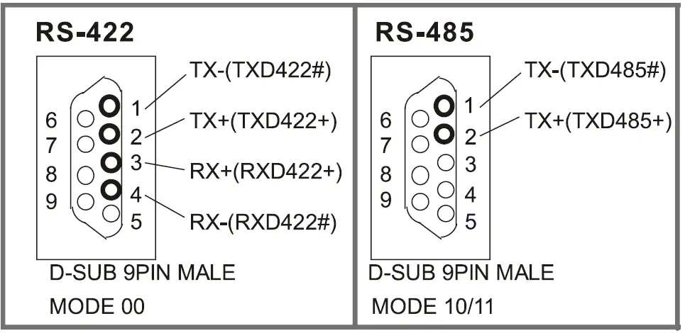
| COM3, COM4: RS-422/428 Serial Port Connectors | |||
| PIN NO. | DESCRIPTION | PIN NO. | DESCRIPTION |
| 1 | RXD422- | 3 | TXD422+/TXD485+ |
| 2 | RXD422+ | 4 | TXD422-/TXD485- |
| S_ATA3, S_ATA4, S_ATA5, S_ATA6: SATA 6Gb/s Connectors | |||
| PIN NO. | DESCRIPTION | PIN NO. | DESCRIPTION |
| 1 | GND | 5 | SATA_RX‐ |
| 2 | SATA_TX+ | 6 | SATA RX+ |
| 3 | SATA_TX‐ | 7 | GND |
| 4 | GND | 8 | N/C |
| SMB1: SM Bus Connector | |||
| PIN NO. | DESCRIPTION | PIN NO. | DESCRIPTION |
| 1 | GND | 3 | SMB_CLK |
| 2 | SMB_DATA | 4 | +5V |
| JUSB3, JUSB4, JUSB5: Internal USB 2.0 Connectors | |||
| PIN NO. | DESCRIPTION | PIN NO. | DESCRIPTION |
| 1 | VCC | 2 | GND |
| 3 | USB_DATA- | 4 | USB_DATA+ |
| 5 | USB_DATA+ | 6 | USB_DATA- |
| 7 | GND | 8 | VCC |
| USB1: Internal USB 3.2 Gen 1 Connector (Type-A) | |||
| PIN NO. | DESCRIPTION | PIN NO. | DESCRIPTION |
| 1 | VCC | 6 | USB3_RX+ |
| 2 | USB_DATA- | 7 | GND |
| 3 | USB_DATA+ | 8 | USB3_TX- |
| 4 | GND | 9 | USB3_TX+ |
| 5 | USB3_RX- | ||
| JUSB3-1: Internal USB 3.2 Gen 1 Connector | |||
| PIN NO. | DESCRIPTION | PIN NO. | DESCRIPTION |
| 1 | VCC | 11 | USB_DATA+ |
| 2 | USB_RX- | 12 | USB_ DATA- |
| 3 | USB_RX+ | 13 | GND |
| 4 | GND | 14 | USB3_TX+ |
| 5 | USB3_TX- | 15 | USB3_ TX- |
| 6 | USB3_TX+ | 16 | GND |
| 7 | GND | 17 | USB3_RX+ |
| 8 | USB3_DATA- | 18 | USB3_RX- |
| 9 | USB3_DATA+ | 19 | VCC |
| 10 | NC | ||
| M2_A1: M.2 A-key Slot | |||
| PIN NO. | DESCRIPTION | PIN NO. | DESCRIPTION |
| 1 | GND | 2 | +3.3V |
| 3 | USB+ | 4 | +3.3V |
| 5 | USB- | 6 | NC |
| 7 | GND | 8 | Module Key |
| 9 | Module Key | 10 | Module Key |
| 11 | Module Key | 12 | Module Key |
| 13 | Module Key | 14 | Module Key |
| 15 | Module Key | 16 | NC |
| 17 | NC | 18 | GND |
| 19 | NC | 20 | NC |
| 21 | NC | 22 | NC |
| 23 | GND | 24 | GND |
| 25 | NC | 26 | NC |
| 27 | NC | 28 | NC |
| 29 | GND | 30 | GND |
| 31 | NC | 32 | NC |
| 33 | GND | 34 | NC |
| 35 | PCIE_TXP1 | 36 | GND |
| 37 | PCIE_TXN1 | 38 | NC |
| 39 | GND | 40 | NC |
| 41 | PCIE_RXP1 | 42 | NC |
| 43 | PCIE_RXN1 | 44 | NC |
| 45 | GND | 46 | NC |
| 47 | PCIE_CLKP0 | 48 | NC |
| 49 | PCIE_CLKN0 | 50 | NC |
| 51 | GND | 52 | PLT_RST |
| 53 | CLKREQ0# | 54 | Pull up +3.3V |
| 55 | PCIE_WAKE | 56 | Pull up +3.3V |
| 57 | GND | 58 | M2_DAT |
| 59 | PCIE_TXP2 | 60 | M2_CLK |
| 61 | PCIE_TXN2 | 62 | NC |
| 63 | GND | 64 | NC |
| 65 | PCIE_RXP2 | 66 | M2_RST |
| 67 | PCIE_RXN2 | 68 | CLKREQ0# |
| 69 | GND | 70 | PCIE_WAKE |
| 71 | PCIE_CLKP1 | 72 | +3.3V |
| 73 | PCIE_CLKN1 | 74 | +3.3V |
| 75 | GND | ||
| M2_M1: M.2 M-key Slot | |||
| PIN NO. | DESCRIPTION | PIN NO. | DESCRIPTION |
| 1 | GND | 2 | +3.3V |
| 3 | GND | 4 | +3.3V |
| 5 | PCIE_RXN3 | 6 | N/C |
| 7 | PCIE_RXP3 | 8 | N/C |
| 9 | GND | 10 | DAS/DSS# |
| 11 | PCIE_TXN3 | 12 | +3.3V |
| 13 | PCIE_TXP3 | 14 | +3.3V |
| 15 | GND | 16 | +3.3V |
| 17 | PCIE_RXN2 | 18 | +3.3V |
| 19 | PCIE_RXP2 | 20 | N/C |
| 21 | GND | 22 | N/C |
| 23 | PCIE_TXN2 | 24 | N/C |
| 25 | PCIE_TXP2 | 26 | N/C |
| 27 | GND | 28 | N/C |
| 29 | PCIE_RXN1 | 30 | N/C |
| 31 | PCIE_RXP1 | 32 | N/C |
| 33 | GND | 34 | N/C |
| 35 | PCIE_TXN1 | 36 | N/C |
| 37 | PCIE_TXP1 | 38 | DEVSLP |
| 39 | GND | 40 | N/C |
| 41 | PCIE_RXN0 | 42 | N/C |
| 43 | PCIE_RXP0 | 44 | N/C |
| 45 | GND | 46 | N/C |
| 47 | PCIE_TXN0 | 48 | N/C |
| 49 | PCIE_TXP0 | 50 | PERST# |
| 51 | GND | 52 | CLKREQ# |
| 53 | REFCLKN | 54 | PEWAKE |
| 55 | REFCLKP | 56 | N/C |
| 57 | GND | 58 | N/C |
| 59 | Module Key | 60 | Module Key |
| 61 | Module Key | 62 | Module Key |
| 63 | Module Key | 64 | Module Key |
| 65 | Module Key | 66 | Module Key |
| 67 | NC | 68 | SUSCLK |
| 69 | PEDET | 70 | +3.3V |
| 71 | GND | 72 | +3.3V |
| 73 | GND | 74 | +3.3V |
| 75 | GND | ||
| M2_B1: M.2 B-key Slot | |||
| PIN NO. | DESCRIPTION | PIN NO. | DESCRIPTION |
| 1 | CONFIG_3 | 2 | +3.3V |
| 3 | GND | 4 | +3.3V |
| 5 | GND | 6 | NC |
| 7 | USB+ | 8 | NC |
| 9 | USB- | 10 | NC |
| 11 | GND | 12 | Module Key |
| 13 | Module Key | 14 | Module Key |
| 15 | Module Key | 16 | Module Key |
| 17 | Module Key | 18 | Module Key |
| 19 | Module Key | 20 | NC |
| 21 | CONFIG_0 | 22 | NC |
| 23 | PCH_WAKE_N | 24 | NC |
| 25 | NC | 26 | NC |
| 27 | GND | 28 | NC |
| 29 | PCIE_RXN1 | 30 | SIM_RST |
| 31 | PCIE_RXP1 | 32 | SIM_CLK |
| 33 | GND | 34 | SIM_IO |
| 35 | PCIE_TXN1 | 36 | SIM_VCC |
| 37 | PCIE_TXP1 | 38 | NC |
| 39 | GND | 40 | NC |
| 41 | PCIE_RXP0 | 42 | NC |
| 43 | PCIE_RXN0 | 44 | NC |
| 45 | GND | 46 | NC |
| 47 | PCIE_TXN0 | 48 | NC |
| 49 | PCIE_TXP0 | 50 | M2_RST |
| 51 | GND | 52 | CLKREQ0# |
| 53 | PCIE_CLKN0 | 54 | PCH_WAKE_N |
| 55 | PCIE_CLKP0 | 56 | NC |
| 57 | GND | 58 | NC |
| 59 | NC | 60 | NC |
| 61 | NC | 62 | NC |
| 63 | NC | 64 | NC |
| 65 | NC | 66 | NC |
| 67 | M2_RST | 68 | NC |
| 69 | M2BCONF | 70 | +3.3V |
| 71 | GND | 72 | +3.3V |
| 73 | GND | 74 | +3.3V |
| 75 | GND | ||
| SIM1: SIM Card Slot | |||
| PIN NO. | DESCRIPTION | PIN NO. | DESCRIPTION |
| C1 | SIM_VCC | C5 | GND |
| C2 | SIM_RST | C6 | NC |
| C3 | SIM_CLOCK | C7 | SIM_IO |
| LAN1, LAN2: External 2.5GbE RJ-45 Connectors | |||
| PIN NO. | DESCRIPTION | PIN NO. | DESCRIPTION |
| 1 | MDIA3- | 5 | MDIA1+ |
| 2 | MDIA3+ | 6 | MDIA2+ |
| 3. | MDIA2- | 7 | MDIA0- |
| 4. | MDIA1- | 8 | MDIA0+ |
| HDMI1: External HDMI Connector | |||
| PIN NO. | DESCRIPTION | PIN NO. | DESCRIPTION |
| 21 | HDMI_DATA2 | 31 | GND |
| 22 | GND | 32 | HDMI_CLK# |
| 23 | HDMI_DATA2# | 33 | N/C |
| 24 | HDMI_DATA1 | 34 | N/C |
| 25 | GND | 35 | HDMI_SCL |
| 26 | HDMI_DATA1# | 36 | HDMI_SDA |
| 27 | HDMI_DATA0 | 37 | GND |
| 28 | GND | 38 | +5V |
| 29 | HDMI_DATA0# | 39 | HDMI_HPD |
| 30 | HDMI_CLK | ||
| CN1, CN2: External USB 3.2 Gen 1 Connectors (Type-A) | |||
| PIN NO. | DESCRIPTION | PIN NO. | DESCRIPTION |
| 1 | VCC | 6 | USB3_RX+ |
| 2 | USB_DATA- | 7 | GND |
| 3 | USB_DATA+ | 8 | USB3_TX- |
| 4 | GND | 9 | USB3_TX+ |
| 5 | USB3_RX- | ||
| CON1: External USB 3.2 Gen 2 Connector (Type-C) | |||
| PIN NO. | DESCRIPTION | PIN NO. | DESCRIPTION |
| A1 | GND | B12 | GND |
| A2 | TX1+ | B11 | RX1+ |
| A3 | TX1- | B10 | RX1- |
| A4 | VBUS | B9 | VBUS |
| A5 | CC1 | B8 | SBU2 |
| A6 | D+ | B7 | NC |
| A7 | D- | B6 | NC |
| A8 | SBU1 | B5 | VCONN |
| A9 | VBUS | B4 | VBUS |
| A10 | RX2- | B3 | TX2- |
| A11 | RX2+ | B2 | TX2+ |
| A12 | GND | B1 | GND |
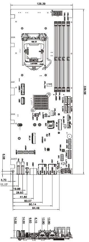
Board Layout: Jumper and Connector Locations


 Intel H61 Processor M-atx Motherboard Quick Installation Guide")
