![]() Item 012904
Item 012904 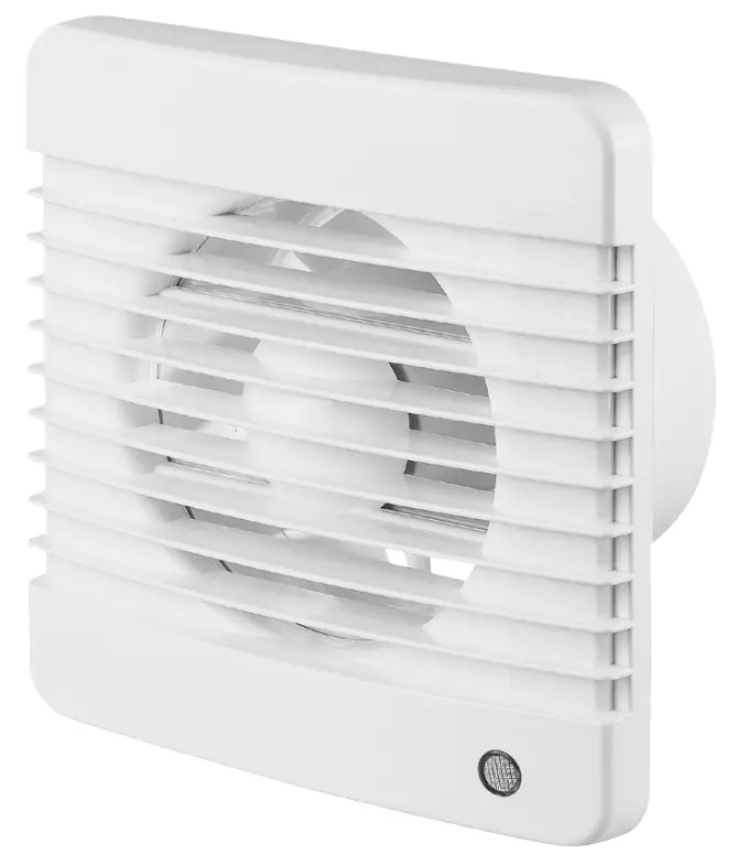
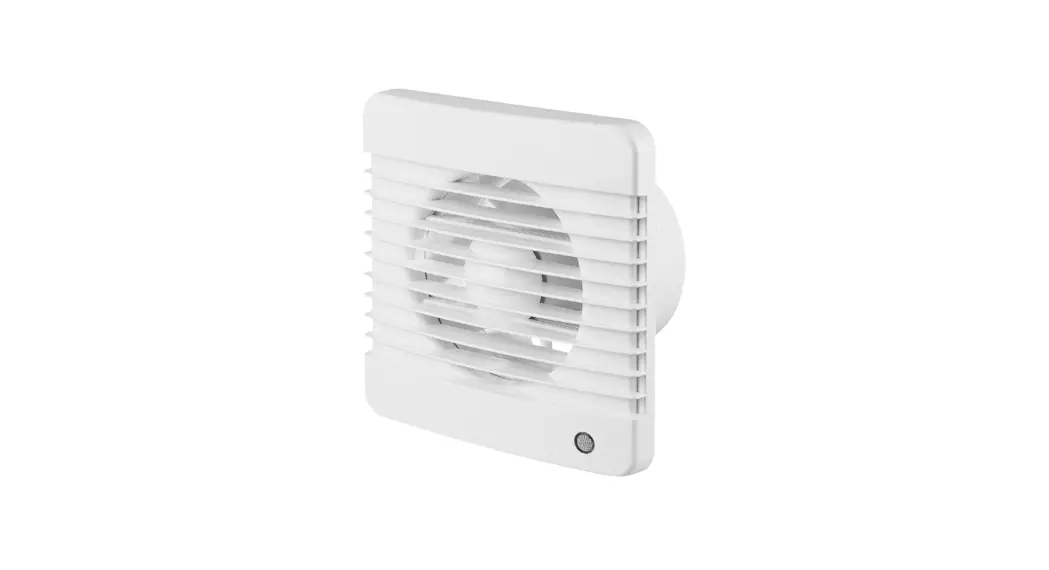
BATHROOM FAN
OPERATING INSTRUCTIONS
Important! Read the user instructions carefully before use. Save them for future reference.
(Translation of the original instructions).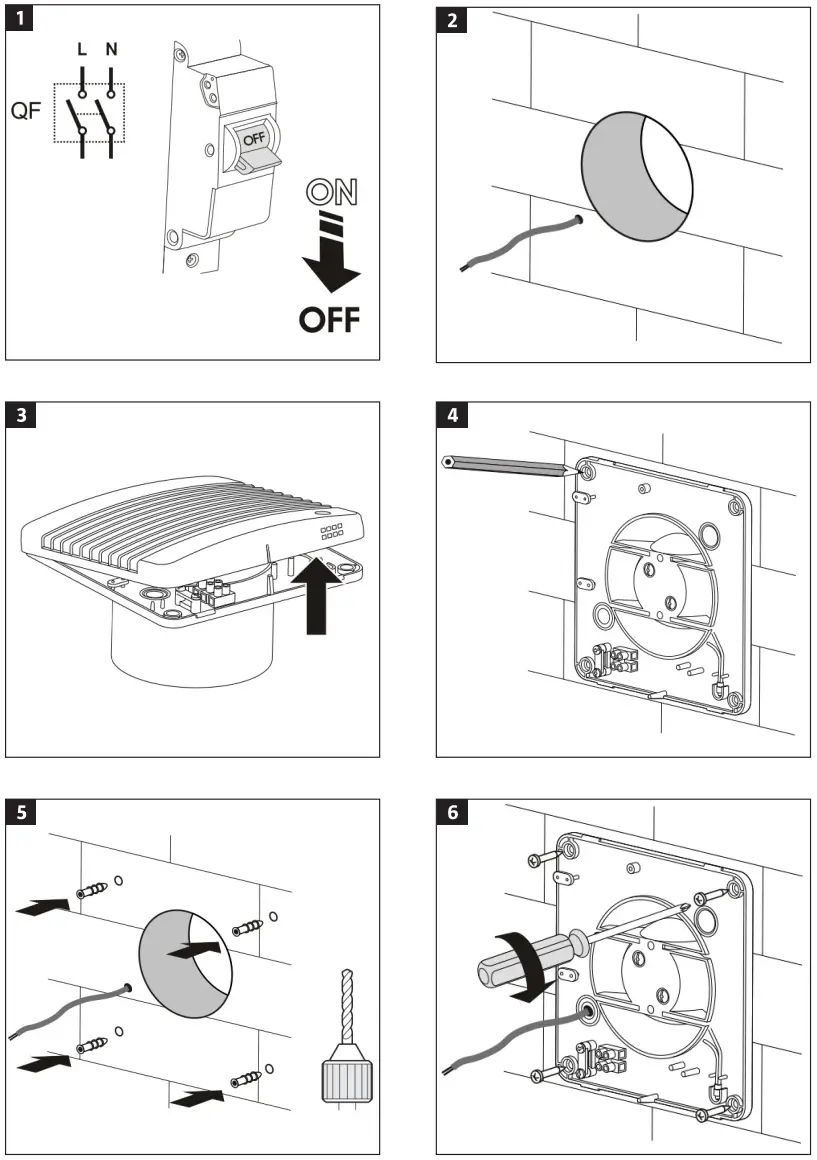
SAFETY INSTRUCTIONS
- Disconnect the product from the mains before connecting, maintenance, and/or repair.
- Installation, maintenance, and/or repairs should be carried out by an authorized electrician and in accordance with these instructions.
- The product is intended to be connected to 230 V 1-phase installations that comply with local regulations.
- The product must be connected via a permanently installed automatic fuse with a minimum contact gap of 3 mm on all terminals.
- Check before installation that the impeller and casing are undamaged.
- There must be no foreign objects in the casing that could damage the fan blades.
- The product must only be used for its intended purpose and in accordance with these instructions. Do not make any modifications to the product.
- The product is not intended to be used by persons (children or adults) with any form of functional disorders, or by persons who do not have sufficient experience or knowledge on how to use it, unless they have received instructions concerning the use of the product from someone who Is responsible for their safety.
- Keep children under supervision to make sure they do not play with the product.
- Take the necessary precautions to prevent smoke, carbon monoxide, and other flammable products from penetrating into the room through open flues or other fire Safety devices.
- Make sure that the air supply is sufficient for correct combustion and adequate chimney draught, to prevent backward flow.
- The transported medium must not contain dust or other solid particles, sticky substances or fibers.
- Do not use the product in explosive environments, e.g. in the vicinity of flammable liquids, gas or dust, or in environments that contain toxic or harmful substances.
- Do not block the openings on the product to attempt to direct or adjust the air flow.
- The product is intended for permanent connection to the mains.
SYMBOLS
| Read the instructions. | |
 | Safety class II. |
 | Approved in accordance with the relevant directives. |
 | Recycle discarded products in accordance with local regulations. |
ELECTRICAL SAFETY
New installations and extensions to existing systems should always be carried out by an authorized electrician. If you have the necessary experience and knowledge (otherwise contact an electrician), you can replace power switches and wall sockets, fit plugs, extension cords, and light sockets. Incorrect installation can result in fatal injury and the risk of fire.
TECHNICAL DATA
| Voltage | 230 V ~ 50 Hz |
| Output | 14 W |
| Flow | 98 m3/h |
| Safety class | II |
| Protection rating | IP34 |
| Speed | 2300 rpm |
| Noise level | 34 dB |
The product Is intended for installation in a wall or ceiling, for connection to round ventilation ducts.
- Switch off the power supply.
FIG. 1
FIG. 2 - Remove the front cover from the product.
FIG. 3 - Mark out and drill the mounting holes.
FIG. 4
FIG. 5 - Fasten the product with screws.
FIG. 6 - Connect the wires to the terminal block.
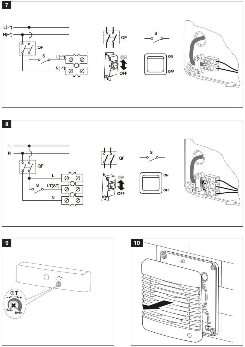
FIG. 7
FIG. 8 - Connect the power supply.
DESIGNATIONS IN WIRING DIAGRAM
L Live wire
N Neutral wire
LT(ST) Control wire for the delay timer
QF Automatic fuse
S External power switch
PUSS
- Fan with a delay timer that starts after the external power switch, e.g. light switch, closes and control voltage is supplied to the terminal LT (ST). When the control voltage is disconnected the fan continues to run for the set time (2 to 30 minutes).
- Turn the potentiometer (T) to the required position to adjust the delay time. FIG. 9
NOTE:
Use the supplied plastic screwdriver to turn and adjust the potentiometers. Do not use a metal screwdriver.
- Switch off the power supply.
- Remove the front cover.
FIG. 10 - Clean the product with a cloth moistened with water and a mild detergent.
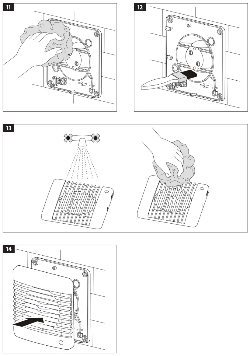
FIG. 11 - Clean the fan blades with a paintbrush.
FIG. 12 - Rinse the front grille under running water. Wipe the surface dry.
FIG. 13 - Fit the front grille.
FIG. 14 - Connect the power supply.
NOTE:
- Make sure no water gets into the electrical components.
- Maintenance should be carried out at least once every 6 months.
| Model: 012904 | |||
| Specific energy consumption | Cold | Medium | Hot |
| -31 kWh/m2 | -14 kWh/m2 | -5 kWh/ma | |
| Type of ventilation unit | Unidirectional | ||
| Type of drive unit | Variable speed | ||
| Type of heating system | N/A | ||
| Thermal efficiency for recycling heat | N/A | ||
| Maximum airflow | 98 m3/h | ||
| Noise level | 54 dB(A) | ||
| Maximum output | 14 W | ||
| Reference flow | 0.019 m3/s | ||
| Reference pressure difference | N/A | ||
| Specific supplied output | 0.092 W/(m3/h) | ||
| Type of control | Manual | ||
| Maximum inner leakage | N/A | ||
| Maximum outer leakage | 3.% | ||
| Annual power consumption | Cold | Medium | Hot |
| 1 kWh | 1 kWh | 1 kWh | |
| Annual savings of primary energy | Cold | Medium | Hot |
| 34 kWh | 17 kWh | 8 kWh | |
| Contact: www.jula.com | |||
Care for the environment!
Recycle discarded product in accordance with local regulations.
Jula reserves the right to make changes. For latest version of operating instructions, see www.jula.comJULA AB, BOX 363, SE-532 24 SKARA
2022-02-18
© Jula AB


