KRAMER VW-9 Video Wall Drivers for Intuitive
This guide helps you install and use your VW-9 for the first time.
Go to www.kramerav.com/downloads/VW-9 to download the latest user manual and check if firmware upgrades are available.
Step 1: Check what’s in the box
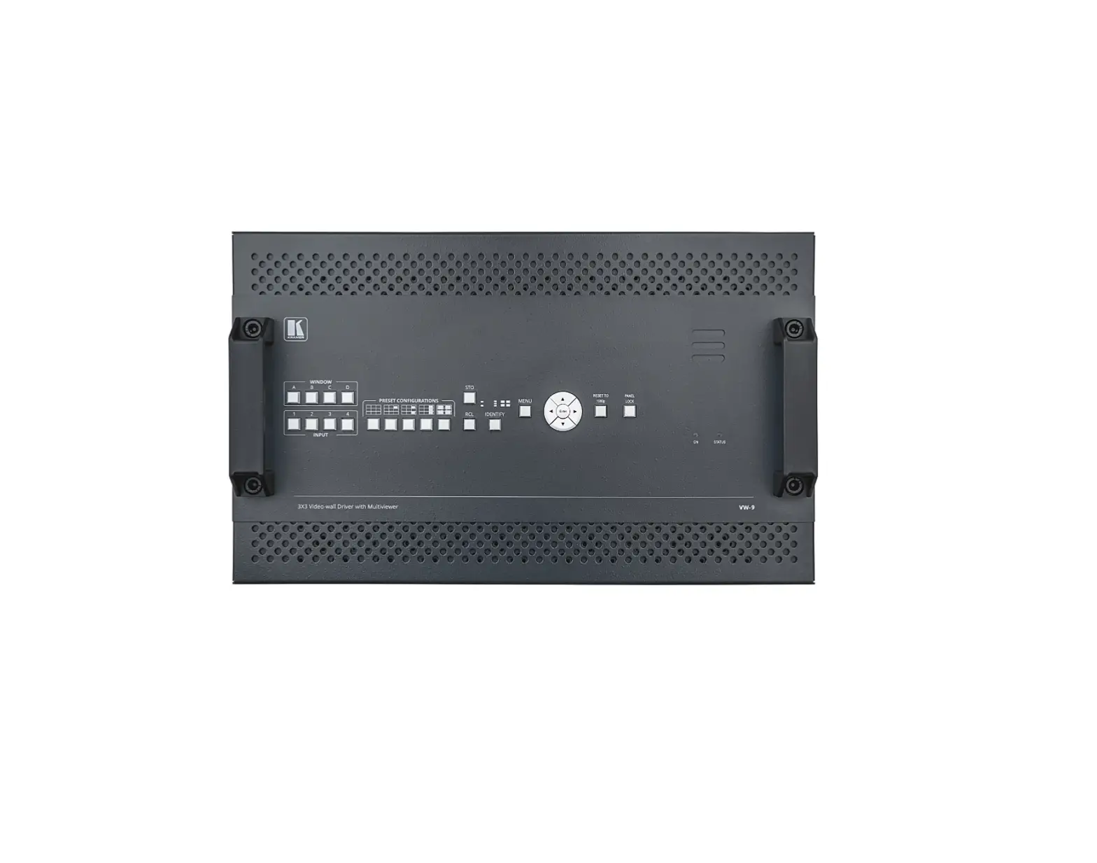
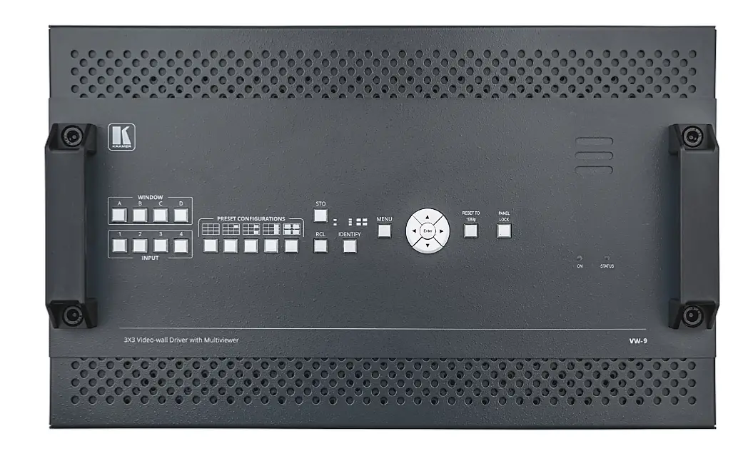
- VW-9 3×3 video-wall Driver with Multiviewer
- 1 Set of rack ears
- 1 Quick start guide
- 2 Power cords
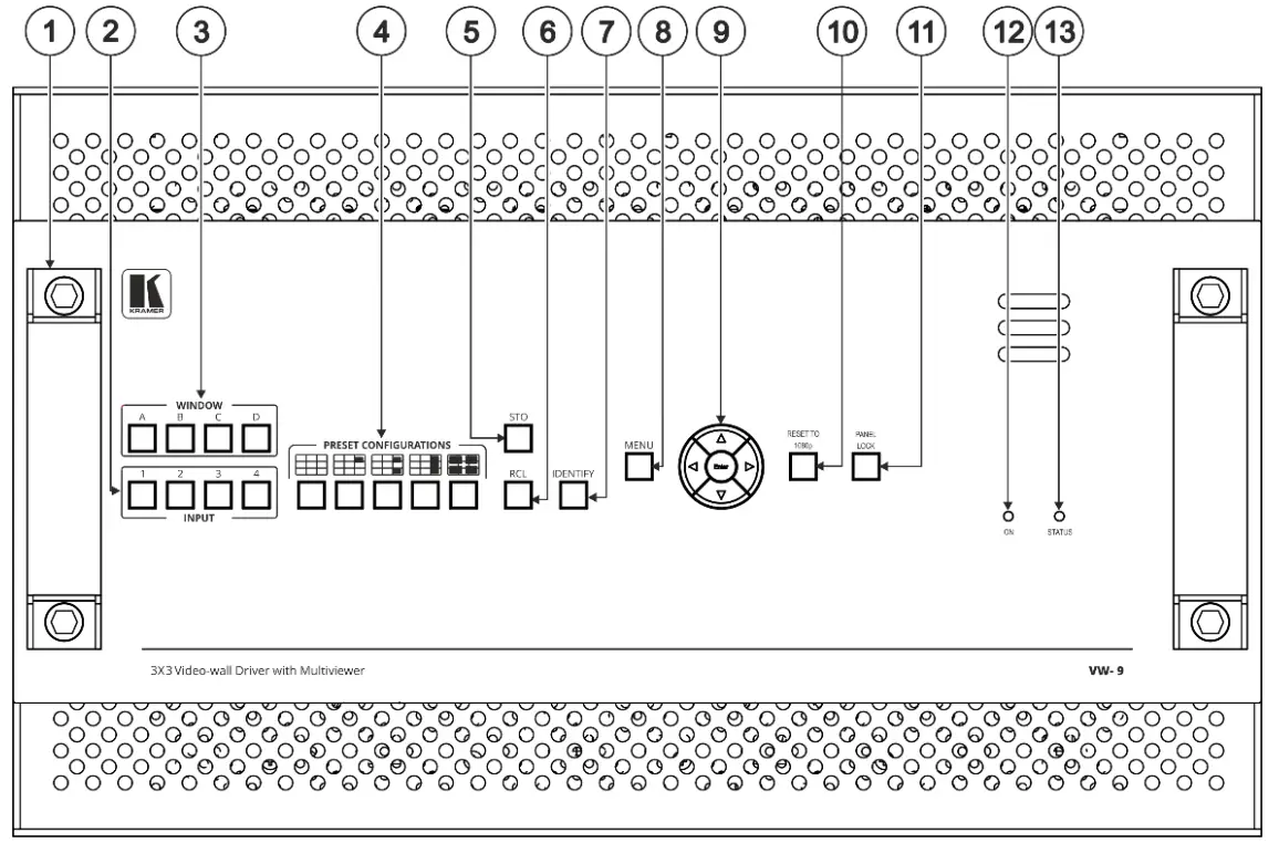
Step 2: Get to know your VW-9
| # | Feature | Function | ||
| 1 | Metal handles (x2) | Rigid metal handles for easy handling. | ||
| 2 | INPUT Buttons (1 to 4) | After pressing a Window button (above), press an input button to select this input for that window. If the wall configuration has only one window, then pressing an input button will select that input for the wall. | ||
| 3 | WINDOW Buttons (A to D) | Press to select window A, B, C or D. | ||
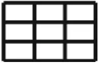
| 4 | PRESET CONFIGURATION Buttons | Press a configuration button to set one of the following presets (each window in the Multiview mode can be resized and repositioned via the embedded web pages): | ||
 | Video wall mode – the video of one source only is presented over the video wall. | |||
 | Multiview mode, presenting 1 PiP window over a parent picture in the video wall. | |||
 | Multiview mode, presenting 2 PiP windows over a parent picture in the video wall. | |||
 | Multiview mode, presenting 3 PiP windows over a parent picture in the video wall. | |||
 | Multiview mode, presenting 4 windows over the video wall. | |||
| 5 | STO Button | Press, followed by an Input button (1 to 4), to save the current wall configuration. | ||
| 6 | RCL Button | Press, followed by an Input button (1 to 4), to recall a pre-saved wall configuration. | ||
| 7 | IDENTIFY Button | When pressed, will identify each window by displaying A, B, C or D in it. | ||
| 8 | MENU Button | Displays the OSD menu. | ||
| 9 | Navigation Buttons | ◀ | Press to decrease numerical values or select from several definitions. When not in the OSD menu, press to reduce the output volume. | |
| ▲ | Press to move up the menu list values. | |||
| ▶ | Press to increase numerical values or select from several definitions. When not in the OSD menu, press to increase the output volume. | |||
| ▼ | Press to move down the menu list. | |||
| ENTER | Press to accept changes and change the SETUP parameters. | |||
| 10 | RESET TO 1080p Button | Press and hold for about 5 seconds to set the output resolutions to 1080p. | ||
| 11 | PANEL LOCK Button | Press and hold to toggle locking and unlocking the front panel buttons. | ||
| 12 | ON LED | Lights green when power is on, and flashes when scaling is not working properly. | ||
| 13 | STATUS LED | Lights green when fan operates properly. Flashes in case of fan malfunction. | ||
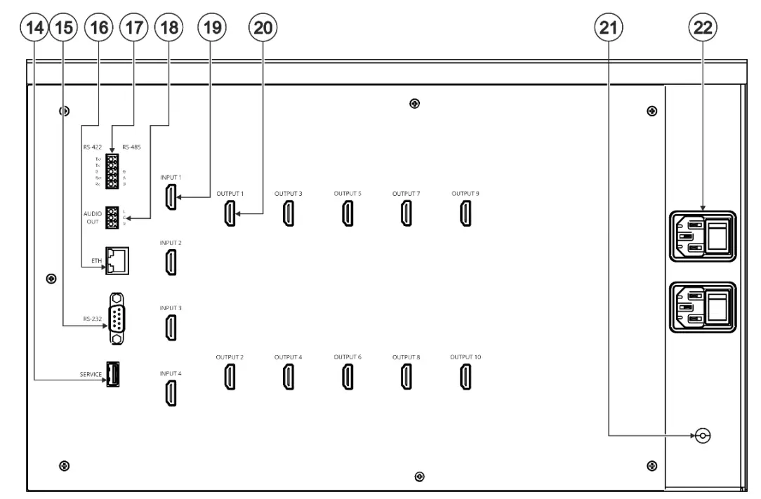
| # | Feature | Function | |
| 14 | SERVICE USB Port | Connect to a PC to perform firmware upgrade. | |
| 15 | RS-232 9-pin D-sub Serial Port Connector | Connect to a PC/serial controller | |
| 16 | ETHERNET RJ-45 Connector | Connect to a PC or other serial controller via a LAN. | |
| 17 | 5-pin Terminal Block Connector | RS-422 (Tx+, Tx-, G, Rx+, Rx-) | Connect to a PC/serial controller. |
| RS-485 (G, A, B) | Connect to a PC/serial controller. | ||
| 18 | AUDIO OUTPUT 3-pin Terminal Block Connector (L, G, R) | Connect to an unbalanced stereo audio acceptor (for example, powered speakers). | |
| 19 | INPUT HDMI Connectors (1 to 4) | Connect to up to 4 HDMI sources. | |
| 20 | OUTPUT HDMI Connectors (1 to 10) | Connect to 9 HDMI displays to create a 3×3 video wall. An additional output can also be connected to an acceptor. | |
| 21 | Grounding Opening | Use a M3 screw to lock the ground wire and connect to ground. | |
| 22 | Mains Power Connector and Power Switch | Plug in the power cord and use the switch to power the unit on or off. | |
The terms HDMI, HDMI High-Definition Multimedia Interface, and the HDMI Logo are trademarks or registered trademarks of HDMI Licensing Administrator, Inc.
Step 3: Mount VW-9
To rack mount the machine, attach both rack ears (by removing the screws from each side of the machine and replacing those screws through the rack ears) or place the machine on a table.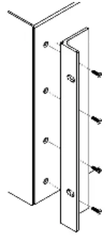
 |
|
Step 4: Connect inputs and outputs
Always switch OFF the power on each device before connecting it to your VW-9.
This diagram shows an example of configuring a 3×3 video wall in multi-viewer mode. Other configurations can be set via the embedded webpages.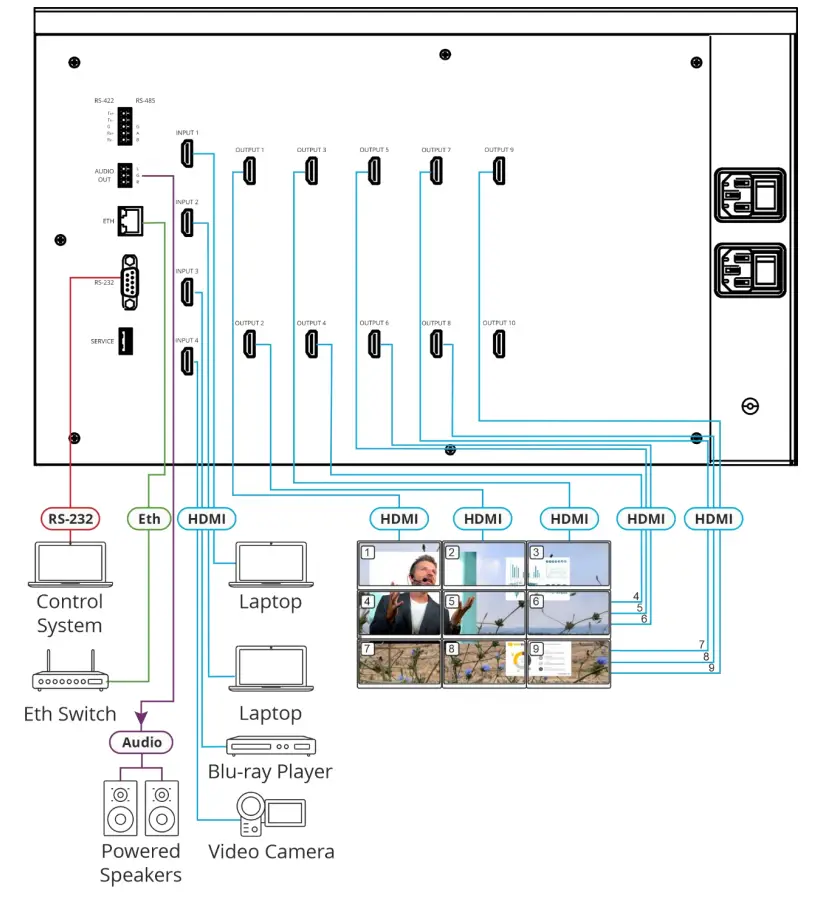
Step 5: Connect power
Connect the power cord to VW-9 and plug it into the mains electricity.
| Safety Instructions (See www.kramerav.com for updated safety information) Caution:
Warning:
|
Step 6: Operate VW-9
Operate Product via:
- Front panel buttons.
- Remotely, by
RS-232/RS-422/RS-485 serial commands transmitted by a touch screen system, PC, or other serial controller. - Embedded web pages via the Ethernet.


