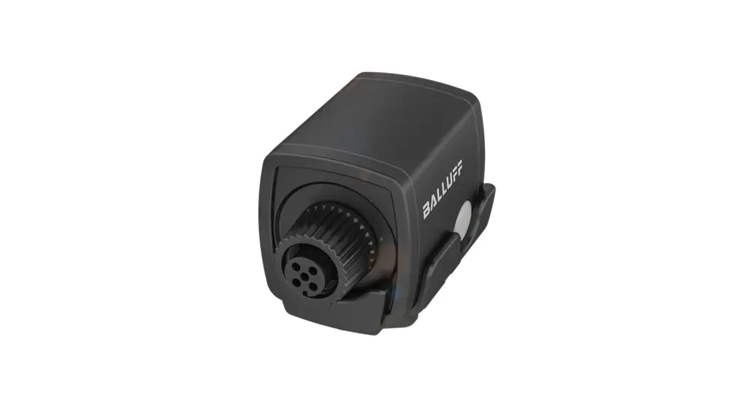
![]() BNI IOW-560-W01-K022
BNI IOW-560-W01-K022
Instruction Manual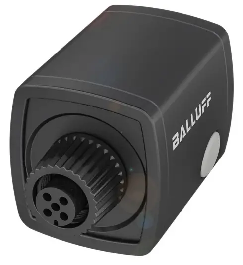
BNI IOW-560-W01-K022
Network interface![]() The CE Mark verifies that our products meet the requirements of the current EU Directive.
The CE Mark verifies that our products meet the requirements of the current EU Directive.
About this guide
This guide provides all the information required for safe use of the IO-Link Wireless Bridge.
It applies to the following models:
- BNI IOW-560-W01-K022
Intended use
The IO-Link Wireless Bridge converts IO-Link to IO-Link Wireless and connects a wired IO-Link device via IO-Link Wireless to an IO-Link Wireless Master. The device can be an IO-Link sensor, an IO-Link actuator or an IO-Link hub. The IO-Link Wireless Bridge is intended for use in industrial applications.
Flawless function in accordance with the specifications in the technical data is ensured only when using suitable original Balluff accessories. Use of any other components will void the warranty.
The module may only be operated with an approved power supply. Only approved lines may be connected. Non-approved use is not permitted and will result in the loss of warranty and liability claims against the manufacturer.
Reasonably foreseeable misuse
The product is not intended for the following applications and areas and may not be used there:
- In safety-oriented applications in which personal safety depends on the device function
- In explosive atmospheres
- in domestic settings (product is class A (EMC limit) for the industrial sector)
Other applicable documents
A comprehensive user’s guide and additional information about this product can be found at www.balluff.com on the product page.
Safety notes
Activities such as installation, connection and startup may only be carried out by qualified personnel.
Qualified personnel are persons whose technical raining, knowledge and experience as well as knowledge of the relevant regulations allow them to assess the work assigned to them, recognize possible hazards and take appropriate safety measures.
The operator is responsible for ensuring that local safety regulations are observed.
In particular, the operator must take steps to ensure that a defect in the product will not result in hazards to persons or equipment.
The product must not be opened, modified or changed. If defects and unresolvable faults occur in the product, take it out of service and secure against unauthorized use.
Design and function
The IO-Link Wireless Bridge is an IO-Link Wireless Class A bridge with an IP67 housing. It has an internal antenna and two M12 connections for data and power.
The IO-Link Wireless Bridge is based on the IO-Link wireless standard for W-Bridge devices and is part of an IO-Link wireless environment. It communicates with an IO-Link Wireless Master.
The required components are an IO-Link Wireless Master, an IO-Link device (an IO-Link sensor, an IO-Link actuator or an IO-Link hub) and a power cable.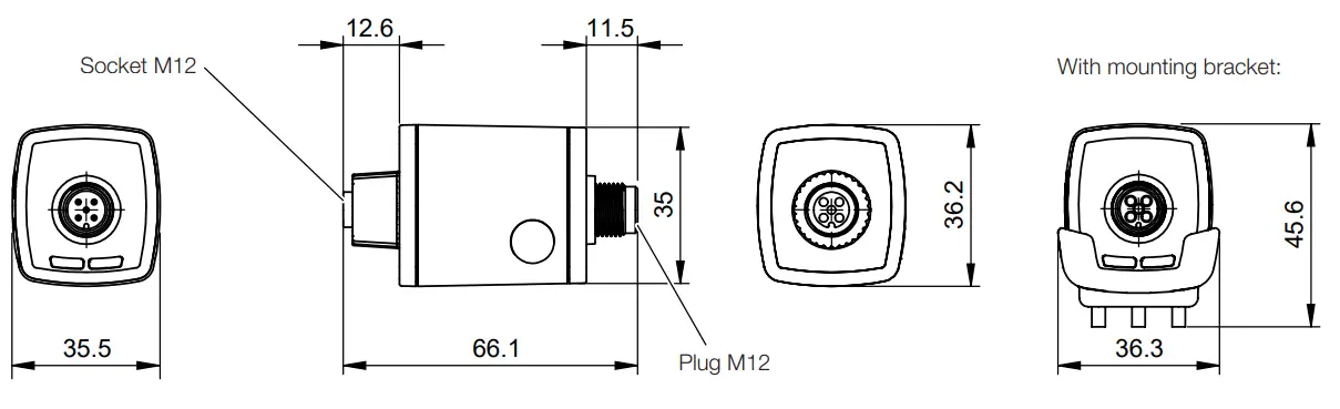 Operating and display elements
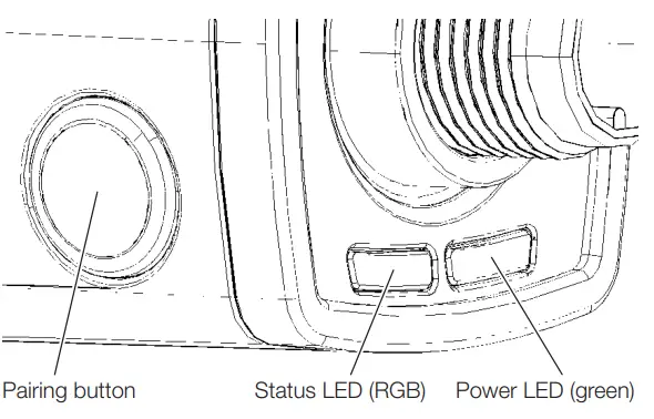 Pairing button
The pairing button is used to replace an existing IO-Link Wireless Bridge with a new one.
The IO-Link Wireless Bridge must be switched off to ensure that the master disconnects before a new module is installed.
Power-LEDs
| Signal | Meaning |
| Green, static | Power is on. |
| Off | No voltage |
Status LED
| Signal | Meaning |
| Magenta | No wireless connection |
| Blue | Wireless bridge is ready for use |
| Green | Wired device ready for operation |
| Yellow | Wired device not ready for operation |
| White | Wireless error |
| Flashing green | Firmware update mode |
Installation
The IO-Link Wireless Bridge can be mounted with or without a mounting bracket (included in scope of delivery).
Installation with mounting bracket
- Secure the mounting bracket to the flange, machine or another surface with M3 screws or cable ties.
- Press the IO-Link Wireless Bridge into the mounting bracket.
![]() The IO-Link Wireless Bridge can simply be pulled out of the mounting bracket to remove it.
The IO-Link Wireless Bridge can simply be pulled out of the mounting bracket to remove it.
Electrical connection
The IO-Link device can be connected to the IO-Link Wireless Bridge directly or via an M12 connector with a cable.
NOTICE
Product damage
The product does not have reverse polarity protection. If the device is connected incorrectly, it may be irreparably damaged.
► Ensure that the polarity is correct.
Power supply![]() Top view of M12 plug, A-coded
Top view of M12 plug, A-coded
| Pin | Signal | Description |
| 1 | L+ | +24 V, module supply |
| 2 | – | n/a |
| 3 | L− | 0 V (GND), module supply |
| 4 | – | n/a |
| 5 | – | n/a |
IO-Link![]()
Top view of M12 socket, A-coded
| Pin | Signal | Description |
| 1 | L+ | +24 V, IO-Link device supply |
| 2 | – | n/a |
| 3 | L− | 0 V (GND), IO-Link device supply |
| 4 | C/Q | IO-Link communication |
| 5 | – | n/a |
Innovating automation
www.balluff.com
| Headquarters | DACH Service Center | Southern Europe Service Center |
| Germany Balluff GmbH Schurwaldstrasse 9 73765 Neuhausen a.d.F. Phone +49 7158 173-0 Fax +49 7158 5010 [email protected] | Germany Balluff GmbH Schurwaldstrasse 9 73765 Neuhausen a.d.F. Phone +49 7158 173-370 [email protected] | Italy Balluff Automation S.R.L. Corso Cuneo 15 10078 Venaria Reale (Torino) Phone +39 0113150711 [email protected] |
| Eastern Europe Service Center | Americas Service Center | Asia Pacific Service Center |
| Poland Balluff Sp. z o.o. Ul. Graniczna 21A 54-516 Wrocław Phone +48 71 382 09 02 [email protected] | USA Balluff Inc. 8125 Holton Drive Florence, KY 41042 Toll-free +1 800 543 8390 Fax +1 859 727 4823 [email protected] | Greater China Balluff Automation (Shanghai) Co., Ltd. No. 800 Chengshan Rd, 8F, Building A, Yunding International Commercial Plaza 200125, Pudong, Shanghai Phone +86 400 820 0016 Fax +86 400 920 2622 [email protected] |
![]()


