Allen-Bradley 2085-IF4 Micro800 4-Channel and 8-Channel Analog Voltage-Current Input and Output Modules Instruction Manual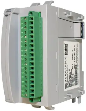
Summary of Changes
This publication contains the following new or updated information. This list includes substantive updates only and is not intended to reflect all changes. Translated versions are not always available for each revision.
| Topic | Page |
| Updated template | Throughout |
| Updated Environment and Enclosure | 2 |
| Updated Attentions | 3 |
| Added Micro870 controller to Overview | 4 |
| Updated Environmental Specifications | 9 |
| Updated Certification | 9 |
Environment and Enclosure
![]() ATTENTION: This equipment is intended for use in a Pollution Degree 2 industrial environment, in overvoltage Category II applications (as defined in EN/IEC 60664-1), at altitudes up to 2000 m (6562 ft) without derating. This equipment is not intended for use in residential environments and may not provide adequate protection to radio communication services in such environments. This equipment is supplied as open-type equipment for indoor use. It must be mounted within an enclosure that is suitably designed for those specific environmental conditions that will be present and appropriately designed to prevent personal injury resulting from accessibility to live parts. The enclosure must have suitable flame-retardant properties to prevent or minimize the spread of flame, complying with a flame spread rating of 5VA or be approved for the application if nonmetallic. The interior of the enclosure must be accessible only by the use of a tool. Subsequent sections of this publication may contain more information regarding specific enclosure type ratings that are required to comply with certain product safety certifications.
ATTENTION: This equipment is intended for use in a Pollution Degree 2 industrial environment, in overvoltage Category II applications (as defined in EN/IEC 60664-1), at altitudes up to 2000 m (6562 ft) without derating. This equipment is not intended for use in residential environments and may not provide adequate protection to radio communication services in such environments. This equipment is supplied as open-type equipment for indoor use. It must be mounted within an enclosure that is suitably designed for those specific environmental conditions that will be present and appropriately designed to prevent personal injury resulting from accessibility to live parts. The enclosure must have suitable flame-retardant properties to prevent or minimize the spread of flame, complying with a flame spread rating of 5VA or be approved for the application if nonmetallic. The interior of the enclosure must be accessible only by the use of a tool. Subsequent sections of this publication may contain more information regarding specific enclosure type ratings that are required to comply with certain product safety certifications.
In addition to this publication, see the following:
- Industrial Automation Wiring and Grounding Guidelines, publication 1770-4.1, for more
installation requirements. - NEMA Standard 250 and EN/IEC 60529, as applicable, for explanations of the degrees of protection provided by enclosures.
Prevent Electrostatic Discharge
- Touch a grounded object to discharge potential static.
- Wear an approved grounding wriststrap.
- Do not touch connectors or pins on component boards.
- Do not touch circuit components inside the equipment.
- Use a static-safe workstation, if available.
- Store the equipment in appropriate static-safe packaging when not in use
North American Hazardous Location Approval
The following information applies when operating this equipment in hazardous locations:
Products marked “CL I, DIV 2, GP A, B, C, D” are suitable for use in Class I Division 2 Groups A, B, C, D, Hazardous Locations and nonhazardous locations only. Each product is supplied with markings on the rating nameplate indicating the hazardous location temperature code. When combining products within a system, the most adverse temperature code (lowest “T” number) may be used to help determine the overall temperature code of the system. Combinations of equipment in your system are subject to investigation by the local Authority Having Jurisdiction at the time of installation.
![]() WARNING: EXPLOSION HAZARD
WARNING: EXPLOSION HAZARD
- Do not disconnect equipment unless power has been removed or the area is known to be nonhazardous.
Do not disconnect connections to this equipment unless power has been removed or the area is known to be nonhazardous. Secure any external connections that mate to this equipment by using screws, sliding latches, threaded connectors, or other means provided with this product. - Substitution of components may impair suitability for Class I, Division 2.
![]() ATTENTION
ATTENTION
- This product is grounded through the DIN rail to chassis ground. Use zinc-plated chromatepassivated steel DIN rail to assure proper grounding. The use of other DIN rail materials (for example, aluminum or plastic) that can corrode, oxidize, or are poor conductors, can result in improper or intermittent grounding. Secure DIN rail to mounting surface approximately every 200 mm (7.8 in.) and use end-anchors appropriately. Be sure to ground the DIN rail properly. Refer to Industrial Automation Wiring and Grounding Guidelines, Rockwell Automation publication 1770-4.1, for more information.
To comply with UL restrictions, this equipment must be powered from a source compliant with the following: Class 2 or Limited Voltage/Current. - To comply with the CE Low Voltage Directive (LVD), all connected I/O must be powered from a source compliant with the following: Safety Extra Low Voltage (SELV) or Protected Extra Low Voltage (PELV).
- Failure to connect a bus terminator module to the last expansion I/O module will result in a controller hard fault.
- Do not wire more than 2 conductors on any terminal
![]() WARNING
WARNING
- When you connect or disconnect the Removable Terminal Block (RTB) with field side power applied, an electrical arc can occur. This could cause an explosion in hazardous locationinstallations. Be sure that power is removed or the area is nonhazardous before proceeding.
- If you connect or disconnect wiring while the field-side power is on, an electric arc can occur. This could cause an explosion in hazardous location installations. Be sure that power is removed or the area is nonhazardous before proceeding.
- If you insert or remove the module while backplane power is on, an electric arc can occur. This could cause an explosion in hazardous location installations. The module does not support “Removal and Insertion Under Power” (RIUP) capability. Do not connect or disconnect the module while power is applied. Be sure power is removed before proceeding.
- Do not unscrew the RTB hold down screws and remove the RTB while power is on. This could cause an explosion in hazardous location installations. Be sure that power is removed before proceeding.
- Do not connect directly to line voltage. Line voltage must be supplied by a suitable, approved isolating transformer or power supply having short circuit capacity not exceeding 100 VA maximum or equivalent.
- When used in a Class I, Division 2, hazardous location, this equipment must be mounted in a suitable enclosure with proper wiring method that complies with the governing electrical codes.
Additional Resources
| Resource | Description |
| Micro830, Micro850, and Micro870 Programmable Controllers User Manual, publication 2080-UM002 | A more detailed description of how to install and use your Micro830, Micro850, and Micro870 programmable controllers. |
| Micro800 Bus Terminator Installation Instructions, publication 2085-IN002 | Information on installing the bus terminator module. |
| Industrial Automation Wiring and Grounding Guidelines, publication 1770-4.1 | More information on proper wiring and grounding techniques. |
Overview
The Micro800™ expansion I/O is a modular I/O that complements and extends the capabilities of Micro850® and Micro870® controllers. These expansion I/O modules interface with the controllers using an I/O expansion port.
Module Overview
Front view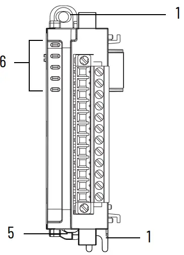
Front view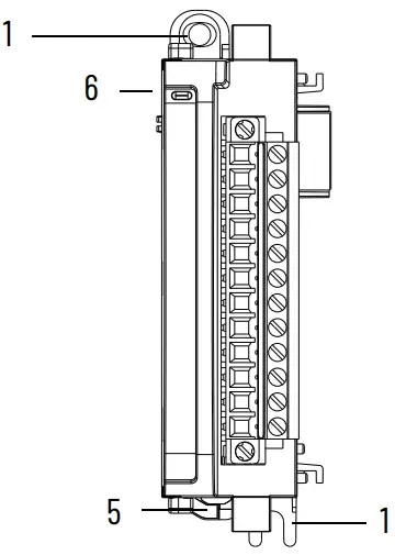
Right top view
2085-IF8, 2085-IF8K
Front view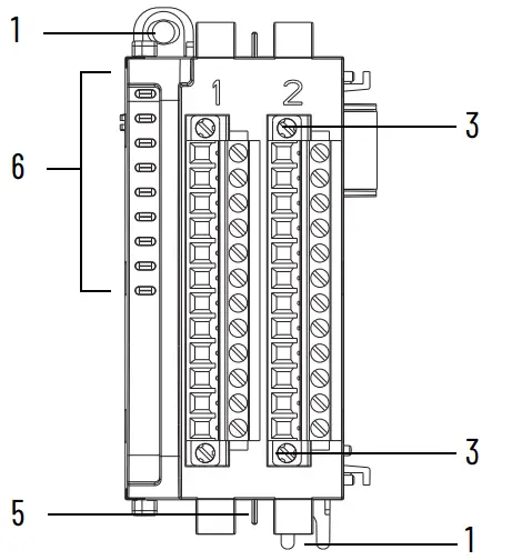
Right top view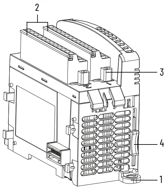
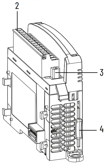
Module Description
| Description | Description | ||
| 1 | Mounting screw hole / mounting foot | 4 | Module interconnect latch |
| 2 | Removable Terminal Block (RTB) | 5 | DIN rail mounting latch |
| 3 | RTB hold down screws | 6 | I/O status indicator |
Mount the Module
For more information on proper grounding guidelines, see the Industrial Automation Wiring and Grounding
Guidelines, publication 1770-4.1.
Module Spacing
Maintain spacing from objects such as enclosure walls, wireways, and adjacent equipment. Allow 50.8 mm (2 in.)
of space on all sides for adequate ventilation, as shown.
Mounting Dimensions and DIN Rail Mounting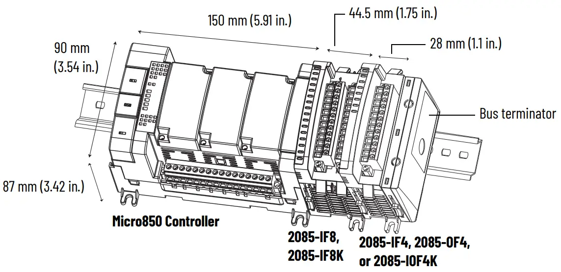
Mounting dimensions do not include mounting feet or DIN rail latches.
DIN Rail Mounting
The module can be mounted using the following DIN rails: 35 x 7.5 x 1 mm (EN 50022 – 35 x 7.5).
 For environments with greater vibration and shock concerns, use the panel mounting method, instead of DIN rail mounting.
Before mounting the module on a DIN rail, use a flat-blade screwdriver in the DIN rail latch and pry it downwards until it is in the unlatched position.
- Hook the top of the DIN rail mounting area of the controller onto the DIN rail, and then press the bottom until the controller snaps onto the DIN rail.
- Push the DIN rail latch back into the latched position.
Use DIN rail end anchors (Allen-Bradley® part number 1492-EA35 or 1492-EAHJ35) for vibration or shock environments.
Panel Mounting
The preferred mounting method is to use two M4 (#8) per module. Hole spacing tolerance: ±0.4 mm (0.016 in.).
For mounting dimensions, see the Micro830®, Micro850, and Micro870 Programmable Controllers User Manual, publication 2080-UM002.
Follow these steps to install your module using mounting screws.
- Place the module next to the controller against the panel where you are mounting it. Make sure that the controller and module are spaced properly.
- Mark drilling holes through the mounting screw holes and mounting feet then remove the module.
- Drill the holes at the markings, then replace the module and mount it. Leave the protective debris strip in place until you are finished wiring the module and any other devices.
System Assembly
The Micro800 expansion I/O module is attached to the controller or another I/O module by means of interconnecting latches and hooks, as well as the bus connector. The controller and expansion I/O modules must terminate with a 2085-ECR Bus Terminator module. Be sure to lock the module interconnect latches and tighten the RTB hold down screws before applying power to the module.
For installation of the 2085-ECR module, see the Micro800 Bus Terminator Module Installation Instructions, publication 2085-IN002.
Field Wiring Connections
In solid-state control systems, grounding and wire routing helps limit the effects of noise due to electromagnetic interference (EMI).
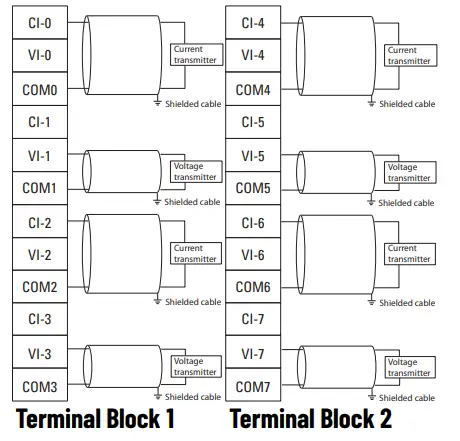
Wire the Module
Included with your 2085-IF4, 2085-OF4, or 2085-OF4K module is a single 12-pin Removable Terminal Blocks (RTB). Included with your 2085-IF8 or 2085-IF8K module are two 12-pin RTB. Basic wiring of your module is shown below.
Basic Wiring to the Module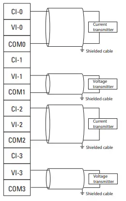
2085-OF4, 2085-OF4K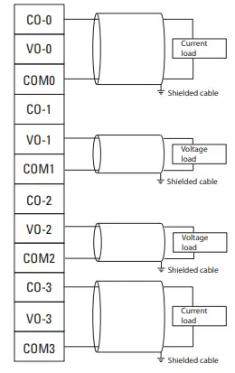
2085-IF8, 2085-IF8K
Specifications
General Specifications
| Attribute | 2085-IF4 | 2085-OF4, 2085-OF4K | 2085-IF8, 2085-IF8K |
| Number of I/O | 4 | 8 | |
| Dimensions HxWxD | 28 x 90 x 87 mm(1.1 x 3.54 x 3.42 in.) | 44.5 x 90 x 87 mm (1.75 x 3.54 x 3.42 in.) | |
| Shipping weight, approx. | 140 g (4.93 oz) | 200 g (7.05 oz) | 270 g (9.52 oz) |
| Bus current draw, max | 5V DC, 100 mA24V DC, 50 mA | 5V DC, 160 mA24V DC, 120 mA | 5V DC, 110 mA24V DC, 50 mA |
| Wire size | |||
| Wiring category(1) | 2 – on signal ports | ||
| Wire type | Shielded | ||
| Terminal screw torque | 0.5…0.6 N•m (4.4…5.3 lb•in)(2) | ||
| Power dissipation, total | 1.7 W | 3.7 W | 1.75 W |
| Enclosure type rating | None (open-style) | ||
| Status indicators | 1 green health indicator 4 red error indicator | 1 green health indicator | 1 green health indicator 8 red error indicators |
| Isolation voltage | 50V (continuous), Reinforced Insulation Type, channel to system. Type tested @ 720V DC for 60 s | ||
| North American temp code | T4A | T5 | |
- Use this Conductor Category information for planning conductor routing. See Industrial Automation Wiring and Grounding Guidelines, publication 1770-4.1.
- RTB hold down screws should be tightened by hand. They should not be tightened using a power tool.
Input Specifications
| Attribute | 2085-IF4 | 2085-IF8, 2085-IF8K |
| Number of inputs | 4 | 8 |
| Resolution Voltage Current | 14 bits (13 bits plus sign bit)1.28 mV/cnt unipolar; 1.28 mV/cnt bipolar1.28 µA/cnt | |
| Data format | Left justified, 16 bit 2 s complement | |
| Conversion type | SAR | |
| Update rate | <2 ms per enabled channel without 50 Hz/60 Hz rejection, <8 ms for all channel 8 ms with 50 Hz/60 Hz rejection | |
| Step response time up to 63% | 4…60 ms without 50Hz/60 Hz rejection – depends on number of enabled channel and filter setting 600 ms with 50 Hz/60 Hz rejection | |
| Input current terminal, user configurable | 4…20 mA (default) 0…20 mA | |
| Input voltage terminal, user configurable | ±10V 0…10V | |
| Input impedance | Voltage terminal >1 MΩ Current terminal <100 Ω | |
| Absolute accuracy | ±0.10% Full Scale @ 25 °C | |
| Accuracy drift with temp | Voltage terminal – 0.00428 % Full Scale/ °C Current terminal – 0.00407 % Full Scale/ °C | |
Input Specifications (Continued)
| Attribute | 2085-IF4 | 2085-IF8, 2085-IF8K |
| Calibration required | Factory calibrated. No customer calibration supported. | |
| Overload, max | 30V continuous or 32 mA continuous, one channel at a time. | |
| Channel diagnostics | Over and under range or open circuit condition by bit reporting | |
Output Specifications
| Attribute | 2085-OF4, 2085-OF4K |
| Number of outputs | 4 |
| Resolution Voltage Current | 12 bits unipolar; 11 bits plus sign bipolar2.56 mV/cnt unipolar; 5.13 mV/cnt bipolar5.13 µA/cnt |
| Data format | Left justified, 16-bit 2 s complement |
| Step response time up to 63% | 2 ms |
| Conversion rate, max | 2 ms per channel |
| Output current terminal, user configurable | 0 mA output until module is configured 4…20 mA (default)0…20 mA |
| Output voltage terminal, user configurable | ±10V 0…10V |
| Current load on voltage output, max | 3 mA |
| Absolute accuracy Voltage terminal Current terminal | 0.133% Full Scale @ 25 °C or better0.425 % Full Scale @ 25 °C or better |
| Accuracy drift with temp | Voltage terminal – 0.0045% Full Scale/ °C Current terminal – 0.0069% Full Scale/ °C |
| Resistive load on mA output | 15…500 Ω @ 24V DC |
Environmental Specifications
| Attribute | Value |
| Temperature, operating | IEC 60068-2-1 (Test Ad, Operating Cold),IEC 60068-2-2 (Test Bd, Operating Dry Heat),IEC 60068-2-14 (Test Nb, Operating Thermal Shock):-20…+65 °C (-4…+149 °F) |
| Temperature, surrounding air, max | 65 °C (149 °F) |
| Temperature, nonoperating | IEC 60068-2-1 (Test Ab, Unpackaged Nonoperating Cold),IEC 60068-2-2 (Test Bb, Unpackaged Nonoperating Dry Heat),IEC 60068-2-14 (Test Na, Unpackaged Nonoperating Thermal Shock):-40…+85 °C (-40…+185 °F) |
| Relative humidity | IEC 60068-2-30 (Test Db, Unpackaged Damp Heat): 5…95% noncondensing |
| Vibration | IEC 60068-2-6 (Test Fc, Operating): 2 g @ 10…500 Hz |
| Shock, operating | IEC 60068-2-27 (Test Ea, Unpackaged Shock): 25 g |
| Shock, nonoperating | IEC 60068-2-27 (Test Ea, Unpackaged Shock): 25 g – for DIN rail mount35 g – for panel mount |
| Emissions | IEC 61000-6-4 |
| ESD immunity | IEC 61000-4-2:6 kV contact discharges 8 kV air discharges |
Environmental Specifications (Continued)
| Attribute | Value |
| Radiated RF immunity | IEC 61000-4-3:10V/m with 1 kHz sine-wave 80% AM from 80…6000 MHz |
| EFT/B immunity | IEC 61000-4-4:±2 kV @ 5 kHz on signal ports±2 kV @ 100 kHz on signal ports |
| Surge transient immunity | IEC 61000-4-5:±1 kV line-line(DM) and ±2 kV line-earth(CM) on signal ports |
| Conducted RF immunity | IEC 61000-4-6:10V rms with 1 kHz sine-wave 80% AM from 150 kHz…80 MHz |
Certifications
| Certification (when product is marked)(1) | Value |
| c-UL-us | UL Listed Industrial Control Equipment, certified for US and Canada. See UL File E322657.UL Listed for Class I, Division 2 Group A,B,C,D Hazardous Locations, certified for U.S. and Canada. See UL File E334470 |
| CE | European Union 2014/30/EU EMC Directive, compliant with: EN 61326-1; Meas./Control/Lab., Industrial Requirements EN 61000-6-2; Industrial ImmunityEN 61000-6-4; Industrial EmissionsEN 61131-2; Programmable Controllers (Clause 8, Zone A & B) European Union 2011/65/EU RoHS, compliant with:EN IEC 63000; Technical documentation |
| RCM | Australian Radiocommunications Act, compliant with: EN 61000-6-4; Industrial Emissions |
| KC | Korean Registration of Broadcasting and Communications Equipment, compliant with: Article 58-2 of Radio Waves Act, Clause 3 |
| EAC | Russian Customs Union TR CU 020/2011 EMC Technical Regulation Russian Customs Union TR CU 004/2011 LV Technical Regulation |
| Morocco | Arrêté ministériel n° 6404-15 du 29 ramadan 1436 |
| UKCA | 2016 No. 1091 – Electromagnetic Compatibility Regulations 2016 No. 1101 – Electrical Equipment (Safety) Regulations2012 No. 3032 – Restriction of the Use of Certain Hazardous Substances in Electrical and Electronic Equipment Regulations |
Rockwell Automation Support
Use these resources to access support information.
| Technical Support Center | Find help with how-to videos, FAQs, chat, user forums, and product notification updates. | rok.auto/support |
| Knowledgebase | Access Knowledgebase articles. | rok.auto/knowledgebase |
| Local Technical Support Phone Numbers | Locate the telephone number for your country. | rok.auto/phonesupport |
| Literature Library | Find installation instructions, manuals, brochures, and technical data publications. | rok.auto/literature |
| Product Compatibility and Download Center (PCDC) | Download firmware, associated files (such as AOP, EDS, and DTM), and access product release notes. | rok.auto/pcdc |
Documentation Feedback
our comments help us serve your documentation needs better. If you have any suggestions on how to improve
our content, complete the form at rok.auto/docfeedback.
Waste Electrical and Electronic Equipment (WEEE)

At the end of life, this equipment should be collected separately from any unsorted municipal waste.
Rockwell Automation maintains current product environmental compliance information on its website at rok.auto/pec.
Rockwell Otomasyon Ticaret A.Ş. Kar Plaza İş Merkezi E Blok Kat:6 34752, İçerenköy, İstanbul, Tel: +90 (216) 5698400 EEE Yönetmeliğine Uygundur
Connect with us.
Costumer Support
Allen-Bradley, expanding human possibility, FactoryTalk, Micro800, Micro830, Micro850, Micro870, Rockwell Automation, and TechConnect are trademarks of Rockwell Automation, Inc. Trademarks not belonging to Rockwell Automation are property of their respective companies.
Publication 2085-IN006E-EN-P – August 2022 | Supersedes Publication 2085-IN006D-EN-P – December 2019
Copyright © 2022 Rockwell Automation, Inc. All rights reserved. Printed in Singapore.
References
 Product Certifications | Rockwell Automation
-
Publication Feedback Form | Rockwell Automation
-
Rockwell Automation Tech Support ... 24 x 7 around the globe!
-
Literature Library | Rockwell Automation
-
Product Compatibility & Download Center from Rockwell Automation
-
Product Environmental Compliance | Rockwell Automation
-
Phone/Onsite Support
-
Support | Rockwell Automation
-
Rockwell Automation (@rokautomation) • Instagram photos and videos
-
Select a Region | Rockwell Automation


