![]()
LO65 Ec
170186.1219/n
Router
Translation of the original operating instructions
WARNING
Please read all safety instructions and directions. Failure to comply with the safety instructions and directions can cause electric shock, fire, and/or serious injuries. Please retain all safety instructions and directions for future reference.
 2006/42/EG 2006/42/EG2014/301EU 2011/65/EU | EN 60745, EN 55014-1, EN 55014-2, EN 61000-3, EN 12100, EN 1037 |
| LO 65 Ec | Art.-Nr. 916901, 916920, 916921, 916922, 916950, 916951, 916955, 916960 |
| Mafell AG D – 78727 Oberndorf, den 21.06.2018 | |
 Dipl.-Ing. Matthias Krauss |  i. V. Dr. Helmut Lauckner |
Signs and symbols
 | This symbol appears at places where you will find instructions for your safety. Non-compliance with these instructions may result in very serious injuries. |
| This symbol indicates a potentially hazardous situation. If this situation is not avoided, the product or objects in its vicinity may get damaged. | |
| This symbol indicates tips for the user and other useful information. |
Product information
for machines with a product no. 916901, 916920, 916921, 916922, 916950, 916951, 916955 or 916960
Manufacturer´s data
MAFELL AG, Beffendorfer Straße 4, D-78727 Oberndorf/Neckar, Phone +49 (0)7423/812-0, Fax +49 (0)7423/812-218
Machine identification
All details required for machine identification are available on the attached rating plate.
| Protection class II |
| CE symbol to document compliance with the basic safety and health requirements according to Appendix I of the Machinery Directive. | |
 | For EU countries only Do not dispose of electric tools together with household waste material! In accordance with the European directive 2002/96/EC on waste electrical and electronic equipment and transposition into national law, obsolete electrical tools must be collected separately and recycled in an environmentally compatible manner. |
| To reduce the risk of injury, please read the operating instructions. |
Technical data
| Universal motor, radio and TV interference suppressed | 230 V~, 50 Hz |
| Input power continuous operation | 2600 W |
| Milling depth adjustment with fine adjustment | 0 – 65 mm (0- 17/16 in.) |
| Revolving depth control turret | 3-stage |
| Tool fastening: | |
| with collets | Ø 6 – 12 mm and Ø 1/2” |
| or with adapter for router bit | M 12 x 1 (M 10) |
| Idling speed | 10000 – 22000 rpm |
| Connection diameter at extraction hood | 35 mm (1 3/8 in.) |
| Weight without mains cable | 6,9 kg (15.2 lbs) |
Noise emission specifications
Noise emission values determined according to EN 60745-1 and EN 60745-2-17:
| Sound power level | Workplace-related emission value | |
| Idling | 99 dB (A) | 88 dB (A) |
| Machining | 106 dB (A) | 95 dB (A) |
The noise measurement was recorded using the saw blade included in the standard equipment.
The values stated are emission levels. Although there is a correlation between emission and emission level, it cannot be reliably derived from this whether additional precautions are necessary. Factors influencing the current immission level existing at the workplace comprise the duration of exposure, the room characteristic, another source of noise, etc. such as e.g. the number of machines and other adjacent machining operations. In addition, the permissible immission level may differ from country to country. This information is nevertheless suitable for providing the machine user with an improved assessment of the hazard and risk.
Vibration specifications
The typical hand-arm vibration is 3.3 m/s².
Scope of supply
| Router LO 65 Ec MaxiMax | LO 65 Ec MidiMAX |
| Item No. 916901, 916920, 916921, 916922 | (specially suited for template milling) |
| 1 parallel guide fence | Item-No. 916950, 916951, 916955 |
| 1 template guide Ø 30 mm | 1 template guide Ø 30 mm |
| 1 collet Ø 8 mm (Ø 1/2“ – GB) | 1 adapter for router bit M 12 x 1 |
| 1 adapter for router bit M 12 x 1 | 1 extraction hood |
| 1 extraction hood | 1 operating tool |
| 1 operating tool | 1 operating manual |
| 1 operating manual | 1 folder “Safety Instructions” |
| 1 folder “Safety Instructions” |
Use according to the intended purpose
The MAFELL router LO 65 Ec is exclusively intended for milling solid wood and panel materials such as chip board, scoreboard, synthetic board, and MDF-board using HSS or TCT milling cutters.
Any other use than described above is not permissible. The manufacturer cannot be held liable for any damage arising from such other use.
So as to use the machine as intended, comply with the operating, maintenance, and repair instructions specified by Mafell.
Residual risks
Danger
Even if used in accordance with its intended purpose and despite confirming the safety instructions, residual risks caused by the intended use will always remain.
- Touching the running milling cutter or the cap nut.
- Breakage of the milling cutter and risk of the milling cutter or pieces of the milling cutter being hurled away.
- The backlash of the machine or the workpiece.
- Touching live parts with the housing open and the mains plug not removed.
- Hearing can be impaired when working for long periods without ear protectors.
- Emission of harmful wood dust during longer operation without extraction.
Safety instructions
Danger
Always observe the following safety instructions and the safety regulations applicable in the respective country of use!
General instructions:
- Children and adolescents must not operate this machine. This rule does not apply to young persons receiving training and being supervised by an expert.
- Never work without the protection devices prescribed for the respective operating sequence and do not make any changes to the machine that could impair safety.
- When operating the machine outdoors, the use of an earth-leakage circuit-breaker is recommended.
- Damaged cables or plugs must be immediately replaced. The replacement may only be carried out by Mafell or an authorized MAFELL service workshop in order to avoid safety hazards. – Avoid sharp bends in the cable. Especially when transporting and storing the machine, do not wind the cable around the machine.
- Only use sharp and undamaged milling cutters. You will achieve improved surfaces and reduce the danger of backlash.
- Before starting up, check the tight seat of the milling cutter and its correct running.
- Only use milling cutters approved for manual feed. – Only begin milling the workpiece when the milling cutter has achieved its full speed.
- Always lead the connecting cable away from the machine to the rear while milling.
- Always mill in a counter direction while working on edges with larger tools.
- Only put down the machine after switching off once the milling cutter has come to a standstill or unscrew the clamping for the automatic reverse stroke on the machine and lock the latter again.
Instructions on the use of personal protective equipment:
- The noise pressure level at the ear generally exceeds 85 dB(A). Operators should therefore wear ear protectors.
- Always wear protective goggles during milling.
- You should wear a dust mask to prevent any damage to your health.
Instructions on operation:
- Never reach into the working range of the milling cutter or underneath the base plate while the machine is running.
- Firmly hold onto the machine with both hands already before switching it on.
- Whenever possible, secure the workpiece against slipping, e.g. with screw clamps.
- Milling cutters must be replaced in good time, as blunt milling cutters do not only increase the danger of backlash but also place an unnecessary strain on the motor. The milling cutters must be clamped in accordance with 4.3.
- Examine the workpiece for foreign objects. Do not mill into metal parts, e.g. nails (danger of backlash).
- The power plug must be pulled before replacing tools, making adjustments, and repairing malfunctions (this also comprises removing jammed chips).
Instructions on service and maintenance:
- Regularly cleaning the machine, especially the adjusting devices and guides, constitutes an important safety factor.
- Only original MAFELL spare parts and accessories may be used. Otherwise, the manufacturer will not accept any warranty claims and cannot be held liable.
Setting/Adjustment
Mains connection
Prior to commissioning make sure that the mains voltage complies with the operating voltage stated on the machine’s rating plate.
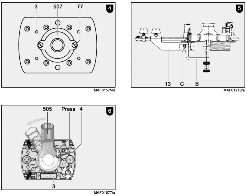
Chip extraction (see Fig. 6)
Connect the machine to a suitable external dust extractor during all work generating a considerable amount of dust. The air velocity must be at least 20 m/s (65.6 ft / sec.).
The internal diameter of the hose connector is 35 mm ( 1 3/8 in.).
Assembly of the extraction hood
Place extraction hood 505 onto base plate 3 and turn it clockwise until it engages.
Disassembly of the extraction hood
Press ratchet lever 4 and turn extraction hood 505 anticlockwise.
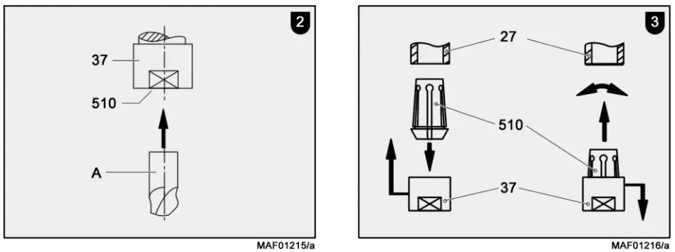
Clamping of milling cutters (see Fig. 1 and 2)
The machine can be placed onto the motor cover to make replacing the milling cutter easier. The router is equipped with a precision collet of Ø 8 mm (Ø 1/2“ on model GB). It is possible to fasten milling cutters with corresponding shaft diameters in this collet. The adapter that is included in the supply facilitates the fastening of milling cutters with female thread M 12 x 1.
Clamping![]() Never tighten the cap nut without a fitted tool as this may damage the collet.
Never tighten the cap nut without a fitted tool as this may damage the collet.
- Push the clean milling cutter shaft A as far as possible into the open collet 510.
- Push the indexing bolt 31 to lock the cutter spindle 27.
- Tighten cap nut 37 by first turning it clockwise by hand and afterward by means of a flat spanner or wrench size 22. It is not necessary to regrip with the flat spanner. Simply turn back the cutter spindle by 90° after you have unscrewed the indexing bolt and relock it with the indexing bolt.
Unclamping
- Reverse order as for clamping.
Collet change (see Fig. 3)
Turn cap nut 37 from cutter spindle 27 to replace the collet. The collet 510 hangs in the cap nut. You can release the collet from the cap nut by forceful tilting and pulling. Forceful pushing causes the collet to engage audibly in the cap nut.![]() Before installing it, clean the cutter spindle cone and the collet. Only mount collets in the cutter spindle that have engaged correctly in the cap nut.
Before installing it, clean the cutter spindle cone and the collet. Only mount collets in the cutter spindle that have engaged correctly in the cap nut.
Assembly and disassembly of the adapter for router bit with female thread (see Fig. 1 and 3)
Assembly
- Instead of collet 510, insert the adapter into cutter spindle cone 27 and tighten it with cap nut 37. The milling cutters can be fastened on the protruding end of the thread.
Disassembly
- Lock the cutter spindle by pressing index bolt 31.
- Slightly unscrew the milling cutter at the adapter.
- Keep the indexing bolt depressed and unscrew the tensioning nut with a flat spanner or wrench size 22.
- Manually screw the cap nut onto the milling cutter collar.
- Twist the cap nut and the milling cutter against each other using the flat spanner. By doing so, you will pull the adapter from the cone.
- You can screw off the parts by hand.
Operation
Initial operation
Personnel entrusted to work with the machine must be made aware of the operating instructions, calling particular attention to the chapter “Safety instructions”.
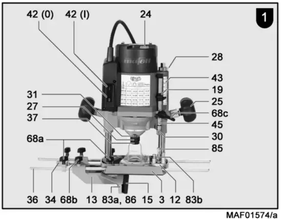
Switching on and off (see Fig. 1)
Danger
Only switch on the machine if the milling cutter has no contact with the workpiece.
- Switching on: Press rocker switch 42 at the end designated with I.
- Switching off: Press rocker switch 42 at the end designated with O. The electronic brake causes the machine to come to a standstill very quickly.
Speed adjustment (see Fig. 1)
Which speed has to be set for which milling cutter-Ø and material can be gathered from the depicted diagram and from the front of the machine.
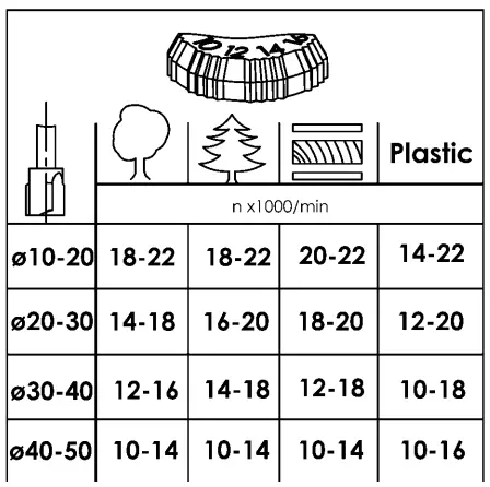
The electronic system keeps the set speed constant. In addition, the electronic system adjusts the motor down in case of overload, i.e. the tool will stop. The machine must then be switched off. Switch on the machine again afterward and continue to work with reduced feed speed.
Danger
Do not work with the router if the electronic system is defective, as this may lead to excessive speeds.
Milling depth adjustment (see Fig. 1)
Clamping device
By turning the handle 25 clockwise you can lock the machine at any milling depth.
Return stroke limit
To avoid unnecessary empty strokes, you can reduce the stroke to the required length by adjusting the knurling nut 28.
Revolving depth control turret
The revolving depth control turret 12 can be used to set three different milling depths. The longest of the stop screws 85 is set to the smallest milling depth while the shortest stop screw 83b is set to the largest milling depth.
Adjustment of milling depth according to scale
- Clamp the milling cutter and place the machine onto the workpiece.
- Unscrew the clamping and contact the workpiece surface with the milling cutter. Then clamp the machine again.
- Adjust depth stop 45 up to the stop screw.
- Set the top edge of the slidable needle 19 on the depth stop to the zero point of scale 43.
- Set the depth stop to the desired milling depth and clamp it with the clamping arm 68c.
- The empty stroke can be reduced to approx. 10 mm with knurling nut 28.
- If you release the clamping at the machine, the reverse stroke will be carried out automatically.
Fine adjustment of milling depth
A fine adjustment of the milling depth can be achieved by turning adjusting nut 30. One turn of the adjusting nut causes a milling depth adjustment of 1 mm.
Work instructions
Plunge milling
While milling ensures that the workpiece is secured, that the router with base plate 3 and/or the limit stops rests as even as possible and with an as large as a possible surface against the workpiece, and that large depths are milled in stages. Once you have set the milling cutter speed, firmly hold onto the machine with both hands and switch on the machine. Plunge into the material up to the limit stop with an even feed and then lock the machine. Only mill in the counter direction.
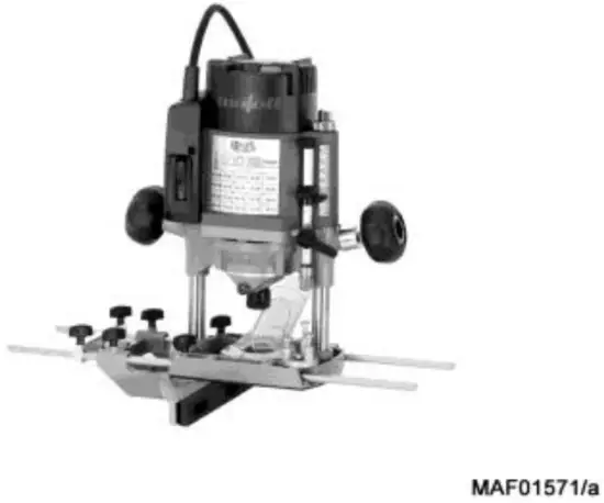
Milling with parallel stop (see Fig. 1)
Parallel stop 13 is used to accurately guide the machine along a straight workpiece edge.
Conversion:
- Push the guide rods 36 laterally into the prism-shaped openings of the base plate.
- Roughly set the parallel stop to the desired distance to the milling cutter and tighten the wing screws 68a.
- Knurling screw 34 permits you to accurately set the distance to the milling cutter. Then tighten the wing screws 68b.
Adjust the sliding pads on the parallel stop
The sliding pads 15 can be pushed together to adjust the top surface during the processing of edge ends. To do so, unscrew cylinder-head screws 83a, 86 and set the sliding pads close to the milling cutter or push them together completely.
Milling according to template
With the template guide 507 (see Fig. 4) it is possible to mill shapes using self-made templates. Screw the template guide onto the underside of base plate 3 using the countersunk screws 77. The template must be wide enough to allow a secure guiding of the machine.
Milling with parallel stop and roller edge guide (see Fig. 5)
(also available as special accessories) The roller edge guide B can be fastened on parallel stop 13 at the end of the screws using hexagon nuts C. With this guide it is possible to carry out milling work parallel to edges of any shape.
Service and maintenance
Danger
Pull the power plug during all service work.
MAFELL machines are designed to be low in maintenance.
The ball bearings used are greased for life. When the machine has been in operation for a longer period of time, we recommend handing the machine in at an authorized MAFELL customer service shop for inspection.
Only use our special grease, order No. 049040 (1 kg tin) for all greasing points.
Storage
If the machine is not used for a longer period of time, it has to be carefully cleaned. Spray bright metal parts with a rust inhibitor.
Troubleshooting
Danger
Determining the causes for existing defects and eliminating these always requires increased attention and caution. Pull the mains plug beforehand!
Some of the most frequent defects and their causes are listed in the following chart. In case of other defects, contact your dealer or the MAFELL customer service.
| Defect | Cause | Elimination |
| The machine cannot be switched on | No mains voltage | Check power supply |
| Carbon brushes worn | Take the machine to a MAFELL customer service shop | |
| Machine switches off automatically during idling or stops during milling | Mains failure | Check mains-side pre-fuse |
| Machine overloaded | Switch the machine off and on again Reduce feed speed | |
| Speed decreases during milling | Excessive chip removal | Reduce chip removal |
| Excessive feed | Reduce feed | |
| Blunt milling cutter | Grind or replace milling cutter | |
| Excessive speed, soft start missing or speed control no longer possible | Defective electronic system | Take the machine to a MAFELL customer service shop |
| Unclean milling pattern | Blunt milling cutter | Grind or replace milling cutter |
| Uneven feed | Mill with constant pressure and reduced infeed | |
| Burn marks on the milled surfaces | Milling cutter that is unsuitable for the operating sequence or blunt | Grind or replace milling cutter |
| Undervoltage shutdown | No mains voltage (power interruption) | Switch the machine off and on again |
| After it has been briefly switched off and on, the machine does not start again | Caused by an electronic system (braking time) | Switch the machine off and on again after approx. 5 seconds |
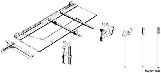
Optional accessories
| 3 | – Template guide Ø 20 mm | Order No. 200693 |
| 3 | – Template guide Ø 27 mm | Order No. 038988 |
| 3 | – Template guide Ø 40 mm | Order No. 038989 |
| 4 | – Collet Ø 6 mm | Order No. 093257 |
| 4 | – Collet Ø 8 mm | Order No. 093256 |
| 4 | – Collet Ø 10 mm | Order No. 093255 |
| 4 | – Collet Ø 12 mm | Order No. 093254 |
| 4 | – Collet Ø 1/4“ | Order No. 093279 |
| 4 | – Collet Ø 1/2“ | Order No. 093276 |
| 5 | – Adapter for router bit M 10 | Order No. 039363 |
| – Adapter for router bit M 12 x 1 | Order No. 201575 | |
| – Template guide RD 30 | Order No. 038971 | |
| – Stair string milling cutter | Order No. 200500 | |
| LO-FA Milling Adapter | Order No. 207200 | |
| Guide rail F 80 | Order No. 204380 | |
| Guide rail F 110 | Order No. 204381 | |
| Guide rail F 160 | Order No. 204365 | |
| Guide rail F 210 | Order No. 204382 | |
| Guide rail F 310 | Order No. 204383 | |
| Single tension clamp | Order No. 207776 | |
| Guide rail F 80-LR | Order No. 207600 | |
| Guide rail F 160-LR | Order No. 207601 | |
| Connecting piece packed F-VS | Order No. 204363 | |
| Adhesive profile packed F-HP 6.8M | Order No. 204376 | |
| Splinter guard packed F-SS 3.4M | Order No. 204375 | |
| Tension clamp packed F-SZ 180MM (2 pcs) | Order No. 207770 | |
| End caps packed F-EK | Order No. 205400 | |
| Recoil stop packed F-RS | Order No. 202867 | |
| Rail bag 160 | Order No. 204626 | |
| Rail bag kit F160/160 consisting of: 2 x F160 + connecting piece + 2 screw clamps + rail bag | Order No. 204805 | |
| Rail bag kit F80/160 with sliding bevel segment consisting of: F80 + F160 + connecting piece + sliding bevel + 2 screw clamps + rail bag | Order No. 204749 |
Exploded drawing and spare parts list
The corresponding information in respect of spare parts can be found on our homepage: www.mafell.com
![]()
MAFELL AG ∙ Beffendorfer Straße 4 ∙ 78727 Oberndorf a.N. ∙ Germany ∙ Tel. +49 7423 812-0
Fax +49 7423 812-218 ∙ E-Mail [email protected] ∙ www.mafell.com
WARRANTY
Upon presentation of the warranty document (original invoice), we will carry out all repairs free of charge in accordance with the applicable warranty provisions, processing, and mounting faults free of charge on presentation of this properly filled-in Guarantee Certificate and your original receipt. This is not valid for consumables and wearing parts. For this purpose, the machine or the appliance is to be forwarded freight paid to our plant or to an authorized MAFELL repair service. Refrain from trying to carry out the repairs yourself as otherwise, your warranty claim will become extinct. We do not accept any liability for any damage resulting from improper handling or normal wear.


