![]() Installation Instructions
Installation Instructions
Model FMT-A-ADPT
Class A Riser Module for the FMT
INTRODUCTION
The Model FMT-A-ADPT module (as shown in Figure 1) from Siemens Industry, Inc., provides the FMT with Class A riser capability. The telephone riser is supervised by the primary FMT.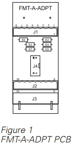
PRE-INSTALLATION
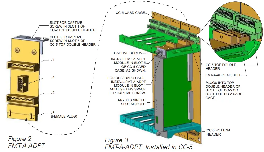
The FMT-A-ADPT is shipped with the bracket for use on the CC-2 or CC-5 Card Cages attached to the FMT-A-ADPT board.![]() To use the FMT-A-ADPT on a CC-2 Card Cage, you must place it in Slot 1 (terminals 9-16) of the top Double Header; on a CC-5 Card Cage you must place it in Slot 5 (terminals 9-16) of the top Double Header.
To use the FMT-A-ADPT on a CC-2 Card Cage, you must place it in Slot 1 (terminals 9-16) of the top Double Header; on a CC-5 Card Cage you must place it in Slot 5 (terminals 9-16) of the top Double Header.
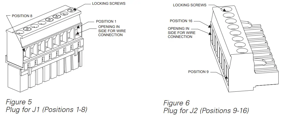
The FMT-A-ADPT is shipped with two removable terminal plugs (see Figures 5 and 6) that are installed in J1 and J2. Remove the terminal plug from the CC-5/CC-2 header (terminals 9-16) where the FMT-A-ADPT will be installed. Transfer the existing field wiring in the connector to connector J2 as explained in the wiring section and discard the connector that was removed.
INSTALLATION
 Remove all system power before installation, first battery then AC. (To power up, connect the AC first, then the battery.)
Install the FMT-A-ADPT (Refer to Figure 2) in the top header of the CC-5/CC-2. Insert the female plug on the end of the FMT-A-ADPT into the appropriate top header (Slot 5 for CC-5 or Slot 1 for CC-2) and then secure the retaining bracket under the XLS module’s retaining captive screw that shares the space. Do not put the FMT-A-ADPT under the bezel of the XLS module. (Refer to Figure 3.)
WIRING
A 46-inch long 10-wire audio cable, P/N 555-150509, connects the FMT-A-ADPT to the FMT to provide Class A riser capability. One end of this wire plugs into J4 of the FMT-A-ADPT and the other end plugs into JP1 of the FMT. The connectors are keyed and fit only one way. Make sure that all cables seat fully into their connectors.![]() Transfer any existing field wiring that was in positions 9-16 of the terminal block header to the corresponding position on J2.
Transfer any existing field wiring that was in positions 9-16 of the terminal block header to the corresponding position on J2.
The screw terminals for J2 can accommodate one 12-22 AWG or two 16-24 AWG (stranded only). For J1, the screw terminals can accommodate one 12-22 AWG or two 16-18 AWG (stranded only). All wiring to the FMT-A-ADPT is power limited.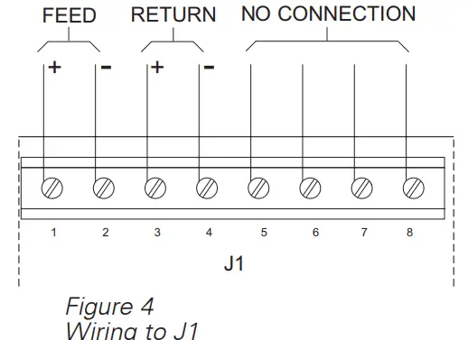
To Connect External Wiring
- Insert the wire to be connected in the desired opening in the side of the removable terminal block.
- Tighten the appropriate locking screw.
- Insert the removable terminal block in the appropriate header (J1 or J2) on the FMT-A-ADPT.
ELECTRICAL RATINGS
| 24V Back Plane Current | 0 |
| Screw Terminal 24V Current | Refer to the FMT Installation Instructions, P/N 315-034100, for information on electrical ratings for the FMT. |
| 6.2V Back Plane Current | 0 |
| 24V Standby Current | 0 |
Siemens Industry, Inc.
Building Technologies Division
Florham Park, NJ
Siemens Building Technologies, Ltd.
Fire Safety & Security Products
2 Kenview Boulevard
Brampton, Ontario
L6T 5E4 Canada
firealarmresources.com
Siemens Industry, Lnc.
Building Technologes Division


