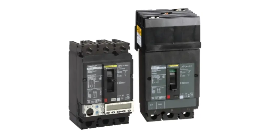
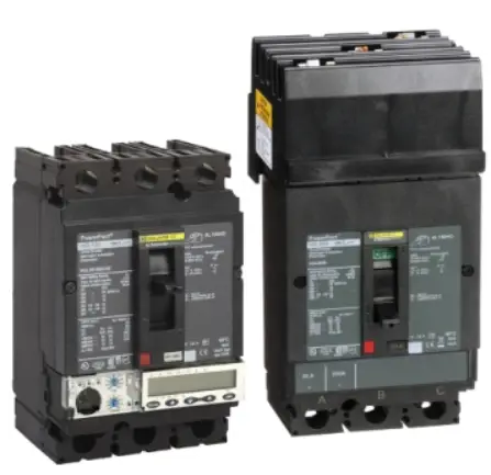
PowerPacT H and J Frame Electronic Trip Circuit Breaker
Product Information
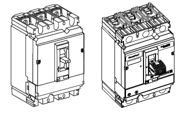
This product is the PowerPacTTM H- and J-Frame Electronic TripCircuit Breaker. It is a device that automatically interrupts an electrical circuit during an overload or short circuit. This circuit breaker is equipped with a Visi-TripTM LED handle that helps in quickly locating a circuit breaker that requires attention. The product comes with internal accessories that need to be installed prior to installing the circuit breaker. It is important to note that failure to follow the instructions may result in death or serious injury.
The required specifications for installation include screws, extension blanks, lugs, and cords. The product has different Ir (x Io) and Io (A) values that depend on the type of cord used. The product also has a DINP chemical that is known to cause cancer and DIDP chemical that is known to cause birth defects or other reproductive harm.
Product Usage Instructions
Before starting the installation, read and understand all instructions provided in the Instruction Bulletin. Turn off all power supplying this equipment before working on or inside equipment. Install the internal accessories as instructed in the bulletins shipped with each accessory. Remove any installed handle extension if it will interfere with the enclosure door closing.
When performing annual maintenance, operate the push to trip button (if equipped) to verify the Visi-Trip functionality. Cycle the circuit breaker from tripped to OFF, and then from OFF to ON and take note of the battery health.
It is important to follow the precautions provided in the Instruction Bulletin to avoid death or serious injury. For more information about the chemicals used in this product, visit: www.P65Warnings.ca.gov.
PowerPacT™ H- and J-Frame Electronic Trip Circuit Breaker Installation
Retain for future use.
Before starting the installation, read and understand all instructions.
Scan the QR code on the product for additional product information.
For information about other products, see our website: https://www.se.com:
For application assistance, please call 1-888-778-2733.
Precautions
DANGER: HAZARD OF ELECTRIC SHOCK, EXPLOSION, OR ARC FLASH
- Apply appropriate personal protective equipment (PPE) and follow safe electrical work practices. See NFPA 70E, CSA Z462 or NOM 029-STPS.
- This equipment must be installed and serviced only by qualified electrical personnel.
- Turn off all power supplying this equipment before working on or inside equipment.
- Always use a properly rated voltage sensing device to confirm power is off.
- Replace all devices, doors, and covers before turning on power to this equipment.
Failure to follow these instructions will result in death or serious injury.
WARNING: This product can expose you to chemicals including DINP, which is known to the State of California to cause cancer, and DIDP which is known to the State of California to cause birth defects or other reproductive harm. For more information go to: www.P65Warnings.ca.gov.
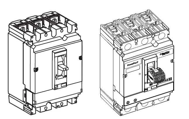
Required for Installation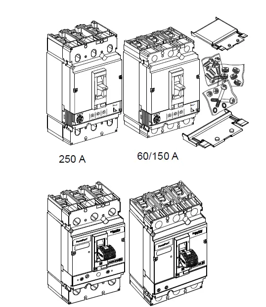 Circuit breaker with Visi-Trip handle shown
| Circuit Breaker | Screws | Extension Blanks | |||||||||
| 1/4-20 x 3/4 in. | 8-32 x 2-5/8 in. | 7/8-16 x 0.56 in. | |||||||||
| HLN4EBL | HLW4EBL | ||||||||||
 | 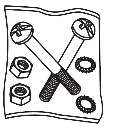 | 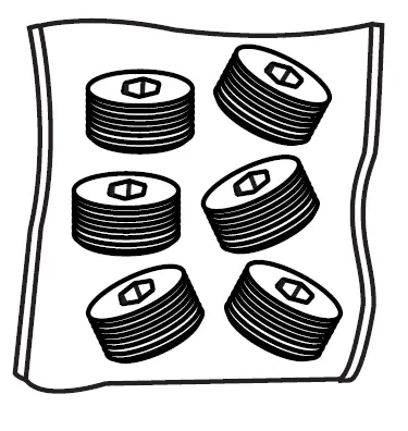 |  |  | |||||||
| I-Line™, MicroLogic™ 1/2/3 trip unit | 60–150 A | — | — | — | — | — | |||||
| 250 A | — | — | 3 | — | — | ||||||
| I-Line, MicroLogic 5/6 trip unit | 60–150 A | — | — | — | 1 | 1 | |||||
| 250 A | — | — | 3 | 1 | 1 | ||||||
| Lugs one end | 60–150 A | 3 | 2 | — | — | — | |||||
| 250 A | 3 | 2 | 3 | — | — | ||||||
| Lugs both ends | 60–150 A | — | 2 | — | — | — | |||||
| 250 A | — | 2 | 6 | — | — | ||||||
| No Lugs | 60–150 A | 6 | 2 | — | — | — | |||||
| 250 A | 6 | 2 | — | — | — | ||||||
No Lugs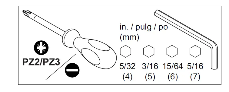
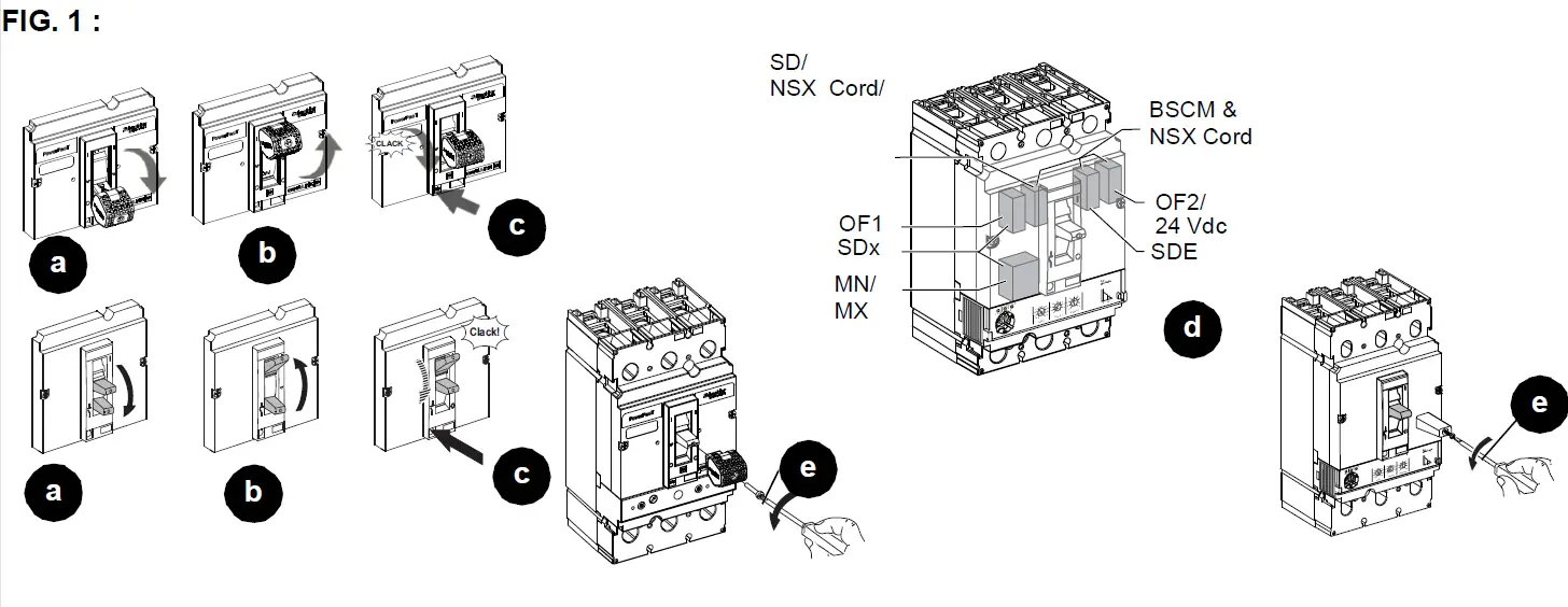
Installation
- Turn off all power supplying this equipment before working on or inside equipment.
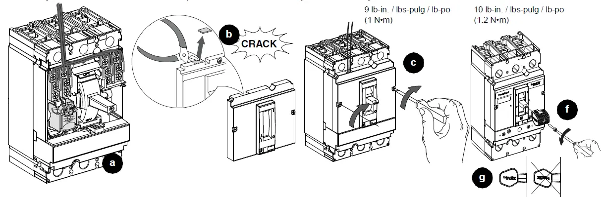
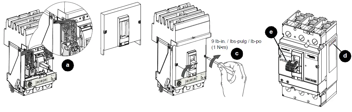
- Trip the circuit breaker (Figure 1, a–c).
Note: All internal accessories must be installed prior to installing the circuit breaker. - Install the internal accessories (d) as instructed in the bulletins shipped with each accessory.
- Remove any installed handle extension (e) if it will interfere with the enclosure door closing.
Visi-Trip™
The Visi-Trip LED handle aids in quickly locating a circuit breaker that requires attention. Inspect the handle position for circuit breaker trip indication. The Visi-Trip handle will flash an LED light as described in Table 1.
Note: When performing annual maintenance in accordance with MCCB Field Testing and Maintenance Guide
(0600IB1201), operate the push to trip button (if equipped) to verify the Visi-Trip functionality. Cycle the circuit breaker from tripped to OFF, and then from OFF to ON and take note of the battery health. See Table 2.
Wait five seconds between handle operation and push-to-trip button operation to ensure that the Visi-Trip handle is on standby mode. Tripping the circuit breaker too soon after toggling may result in the Visi-Trip handle not operating as intended.1
TABL. 1 :
| Light Pattern | Indicator / |
| Fast flash for two seconds. | Battery low (20% remaining). |
| Long duration slow flash (continuous flash up to for six hours). | Inspect the handle position for circuit breaker trip indication. 1 |
- Refer to the Schneider Electric Frequently Asked Questions page. https://www.se.com/us/en/faqs/home/ for more information.
- If a nuisance LED flashing occurs on ON or OFF position, it can be reset by toggling the circuit breaker. If toggling the circuit breaker is not desired, LED flashing will reset after six ours.
Individually-Mounted Circuit Breaker Installation
DANGER: HAZARD OF ELECTRIC SHOCK, EXPLOSION, OR ARC FLASH
Install circuit breaker so minimum clearance distance to grounded metal is maintained.
Failure to follow these instructions will result in death or serious injury.
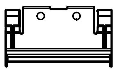
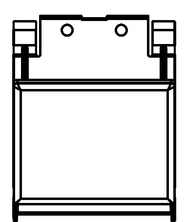
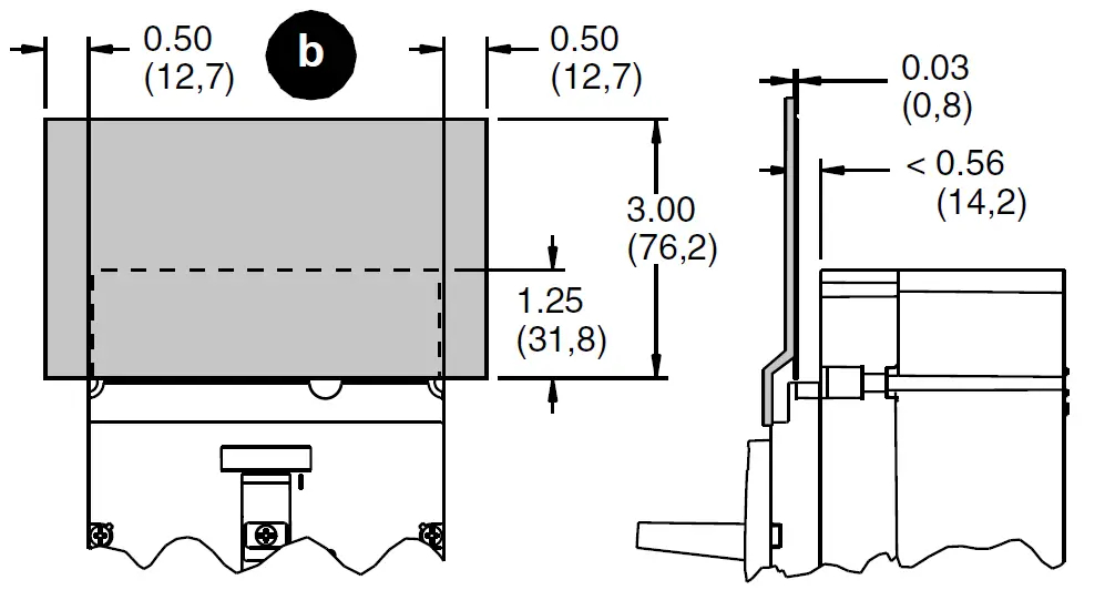
- Check electrical clearances (Figure 2, a–c).
FIG. 2 :Clearances 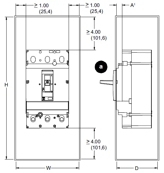
J-Frame Enclosure Insulation2 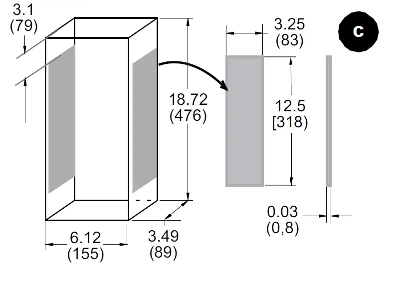
Fiber Insulating Plate
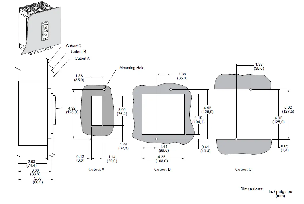
Enclosure Dimensions
 | 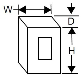 | ||
| Frame | Standard (80%) Rated | 100% Rated / | |
| HD/HG/HJ/HL | 15–150 A | 15.6 x 6.12 x 3.49 in. (396 x 155 x 89 mm) | 15.6 x 6.12 x 3.49 in. (396 x 155 x 89 mm) |
| HR | 18.13 x 8.63 x 4.13 in. (461 x 219 x 105 mm) | 62 x 22.5 x 14 in. (1575 x 572 x 356 mm) | |
| JD/JG/ JJ/JL2 | 150–250 A | 18.72 x 6.12 x 3.49 in. (476 x 155 x 89 mm) | 18.72 x 6.12 x 3.49 in. (476 x 155 x 89 mm) |
| JR | 28.5 x 12.38 x 5.38 in. (724 x 314 x 137 mm) | 62 x 22.5 x 14 in. (1575 x 572 x 356 mm) | |
- If dimension “A” is less than 0.56 in. (14.2 mm), attach fiber insulating plate (not provided) to enclosure cover.
- Insulation required if circuit breaker side < 4.13 in. (105 mm) from metal.
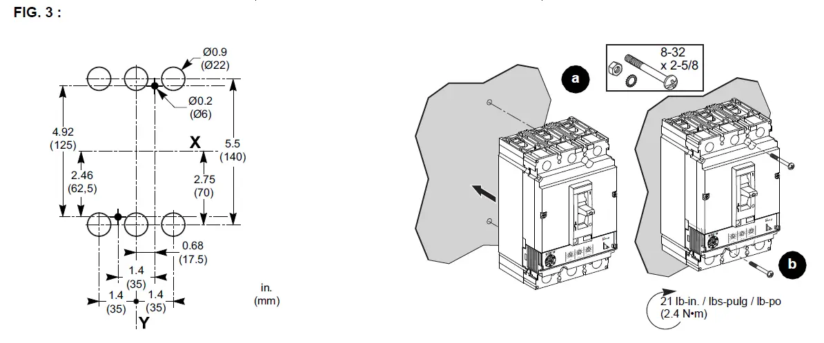
Install the circuit breaker (Figure 3, a– b).
I-Line Circuit Breaker Installation
NOTICE /: HAZARD OF EQUIPMENT DAMAGE
- Do not adjust jaws.
- Do not remove joint compound.
- If necessary, use Square D joint compound PJC7201.
Failure to follow these instructions can result in equipment damage.
- Rack the circuit breaker onto the bus (Figure 4, a–b).
- Tighten the mounting bracket screw (c–d).
- For circuit breakers with MicroLogic™ 5 or 6 trip units, attach a blank extension HLN4EBL (narrow) or HLW4EBL (wide) to the equipment dead front (e-f).
See installation bulletin 80030-695-02 for additional information on installing blank extensions.

Cable Installation
- Note: If needed, install lugs as directed in the instruction shipped with the lug kit.
To convert AL250JD lugs to AL175JD lugs, use the included wire binding screws and the instructions packed with the screws. - Note: See Table 2 for strip lengths and torques.
Notice: HAZARD OF FALSE TORQUE INDICATION
Do not allow conductor strands to interfere with threads of wire binding screws.
Failure to follow these instructions can result in equipment damage.
TABL. 2 :
 |  |  |  |  | ||
| AL150HD | H-frame | 60/100/150 A | (1) Al/Cu | 14–10 AWG (3,5–6 mm2) | 0.65 in. (16 mm) | 50 lb-in. / lbs-pulg / lb-po (5 N•m) |
| 8–3/0 AWG (10–95 mm2) | 0.65 in. (16 mm) | 120 lb-in. / lbs-pulg / lb-po (14 N•m) | ||||
| CU150HD | H-frame | 60/100/150 A | (1) Cu | 14–2/0 AWG (2,5–70 mm2) | 0.65 in. (16 mm) | 120 lb-in. / lbs-pulg / lb-po (14 N•m) |
| AL175JD1 | J-frame | 60/100/150 A | (1) Al/Cu | 4–4/0 AWG (50–95 mm2) | 1 in. (25 mm) | 225 lb-in. / lbs-pulg / lb-po (26 N•m) |
| AL250JD | J-frame | 250 A | (1) Al/Cu | 3/0 AWG–350 kcmil (120–185 mm2) | 1 in. (25 mm) | 225 lb-in. / lbs-pulg / lb-po (26 N•m) |
| CU250JD | J-frame | 250 A | (1) Cu | 1/0 AWG–300 kcmil (50–185 mm2) | 1 in. (25 mm) | 250 lb-in. / lbs-pulg / lb-po (28 N•m) |
- For wire sizes smaller than 3/0 AWG, remove wire binding screws and replace with 7/8-15 x 0.56 screws, provided. /
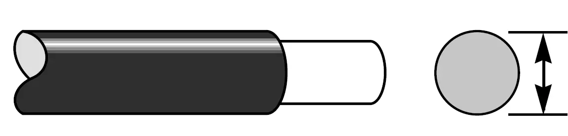
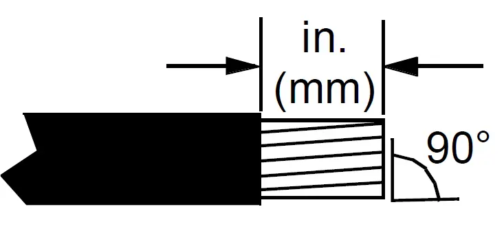
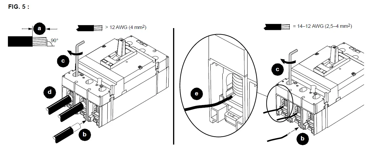
- Preform the conductors to their final configuration. Strip the conductor ends (Figure 5, a). Do not nick strands.
- Install the cables in the lugs and torque the wire binding screws (b–c).
- Install wire larger than 12 AWG in center of channel (d).
- Install 14–12 AWG wire on the side of channel (e) on all lugs to avoid damage to wire.
Bus Installation
Note: If terminal nut inserts are not installed, install the terminal nut inserts as directed in the instructions shipped with the terminal nut kit.
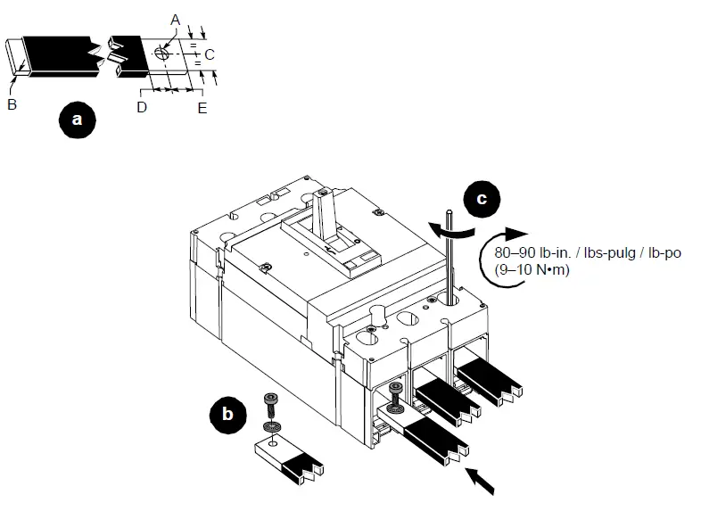
- Prepare the bus connections as shown (Figure 6, a).
- Install the bus connections, using the supplied hardware (b–c).
FIG. 6 :
| Dimension | H-frame | J-frame |
| A | 0.250 in. (6.4 mm) | 0.250 in. (6.4 mm) |
| B | 0.125–0.375 in. (3.2–9.5 mm) | 0.125–0.375 in. (3.2–9.5 mm) |
| C | 0.50 in. (12.7 mm) | 0.50–0.75 in. (12.7–19.1 mm) |
| D | 0.3 in. (7.6 mm) | 0.625 in. (15.9 mm) |
| E | 0.3 in. (7.6 mm) | 0.375 in. (9.5 mm) |
 Control Wiring Installation
(All Circuit Breakers)
Note: Refer to the bulletin shipped with each accessory for accessory installation instructions.
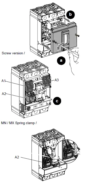
- Remove accessory cover (Figure 7, a–b).
- Install auxiliary devices into corresponding accessory compartments (c).
FIG. 7 :
| Auxiliary Devices | |||||
| OF | Auxiliary contact | A1, A3 | |||
| SD | Alarm switch | A1 | |||
| MN | Under voltage trip | A2 | |||
| MX | Shunt trip | A2 | |||
| SDE | Overcurrent trip | A3 | |||
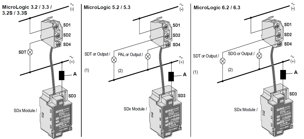
| SDx | Relay module | A1 & A2 | 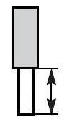 | 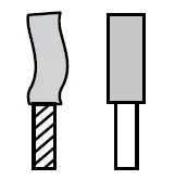 | |
| SDTAM | Relay module | A1 & A2 | |||
| NSX Cord Cordón NSX Cordon NSX | Communications cord | A3 alone A1 with BSCM / A3 solo A1 con BSCM | 7 mm 0.27 in. | 1–2.5 mm2 18-14 AWG | |
| 1.4±0.14 N•m 12±1.2 lb-in. | |||||
| BSCM | Breaker status communication module | A3 | |||
| 24 Vdc Terminal block | Power supply terminal block | A3 | |||
| MN Spring clamp | Undervoltage trip spring clamp | A2 | 1 | ||
| MX Spring clamp | Shunt trip spring clamp | A2 | 7 mm 0.27 in.  0.5–1.5 mm² 0.5–1.5 mm²20–16 AWG | ||
- Multi-stranded end only.
Note: SDx or SDTAM accessories require a fuse. A: 200 mA fuse required, Bussman Fuse KTK-2/10 or equivalent.
NOTICE: HAZARD OF EQUIPMENT DAMAGE- Tighten all accessory cover screws to stated torque.
- Do not overtorque screws.
- Do not use power equipment to torque screws.
Failure to follow these instructions can result in equipment damage.
- Route the wiring (Figure 8, a).
- Replace the accessory cover (b–c), being careful not to pinch the wires when installing the cover.
Note: Confirm that the catalog number on the side accessory label (d) and on the accessory cover (e) match. - Replace Visi-Trip handle (f), note proper orientation (g).
- Mark on the side accessory label (d) which device was installed..
 A: 200 mA fuse required, Bussman Fuse KTK-2/10 or equivalent.
FIG. 8 :
Individually-Mounted Circuit Breakers
I-line Circuit Breakers
Trip Unit Adjustment
MicroLogic 2 and 3 Trip Units:
Set the trip unit using the dials on the front of the trip unit (Figure 9, a–d). See Figure 10 for dial information.
See bulletin 48940-310-01, MicroLogic™ 1, 2, and 3 Electronic Trip Unit—Users Manual, for more information on the trip unit.
FIG. 9 :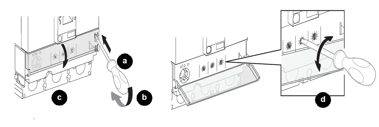
For example: To set Ir to 80, rotate dial until arrow points to 80.
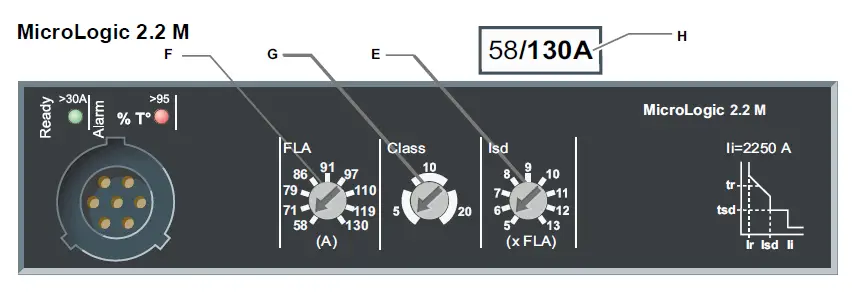
FIG. 10 : 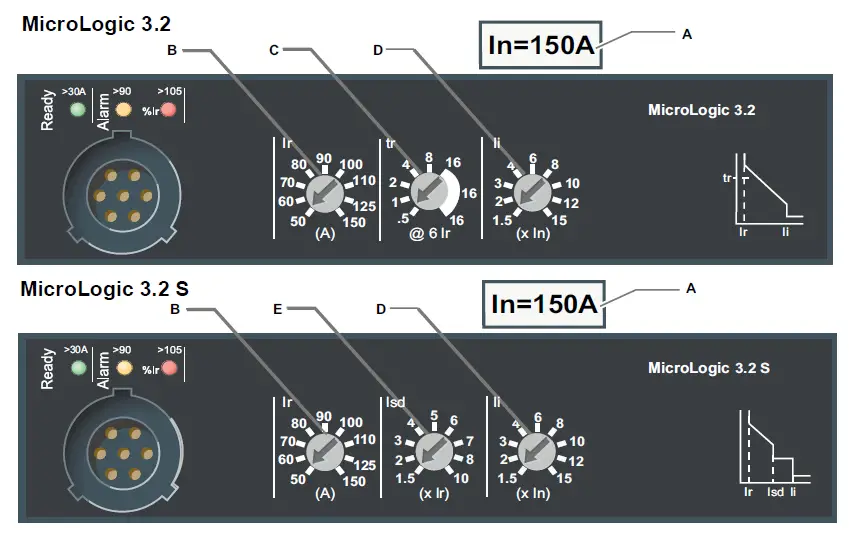
- A. Sensor rating In
- B. Long-time protection pickup setting dial Ir
- C. Long-time protection time delay setting dial tr
- D. Instantaneous protection pickup setting dial Ii
- E. Short-time protection pickup setting dial Isd
- F. Full load amp setting dial FLA
- G. Long-time protection trip class dial Class
- H. FLA adjustment range

Protective Functions Trip Curve 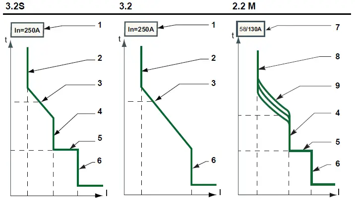
| N | Function | MicroLogic Trip Unit | ||
| 3.2S | 3.2 | 2.2 M | ||
| 1 | In | N | N | — |
| 2 | Ir | A | A | — |
| 3 | tr | N | A | — |
| 4 | Isd | A | — | A |
| 5 | tsd | N | — | N |
| 6 | Ii | A | A | N |
| 7 | FLA Min/Max | — | — | N |
| 8 | FLA | — | — | A |
| 9 | Cl | — | — | A |
- A = Adjustable
- N = Not Adjustable
- _ = Not Available
| Function | Description |
| In | Sensor rating / Valor nominal del sensor |
| Ir | Long-time protection pickup |
| tr | Long-time protection time delay |
| Isd | Short-time protection pickup |
| tsd | Short-time protection time delay |
| Ii | Instantaneous protection pickup |
| FLA Min/Max | Full load amp adjustment range |
| FLA | Full load amp setting |
| Cl | Long-time protection trip class |
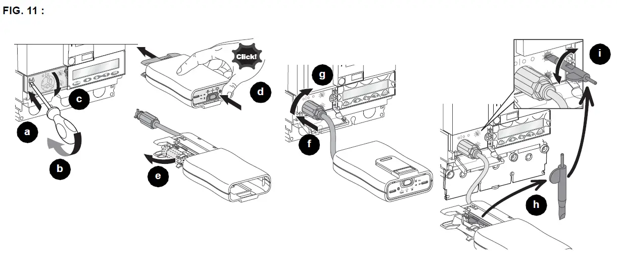
MicroLogic 5 and 6 Trip Units:
Set the protection functions:
- The Pocket Tester or the UTA Tester can be used to power the MicroLogic 5/6 trip unit (Figure 11, a–g). Use enclosed screwdriver to adjust dial settings if necessary (h–i).
- Use the keypad for fine adjustments.
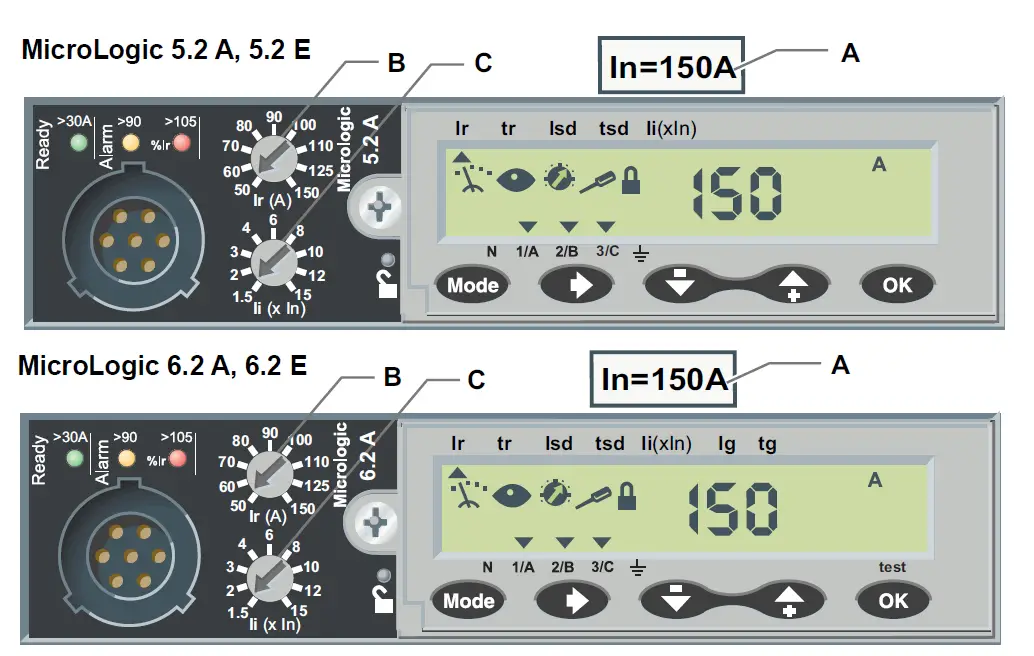
See Figure 12 for dial information.
See bulletin 48940-312-01, MicroLogic™ 5 and 6 Electronic Trip Units—Users Manual, for more information on setting and operation of the trip unit.
- A. Sensor rating In
- B. Long-time protection pickup setting dial Ir
- C. Instantaneous protection pickup setting dial Ii
Protective Functions Trip Curve 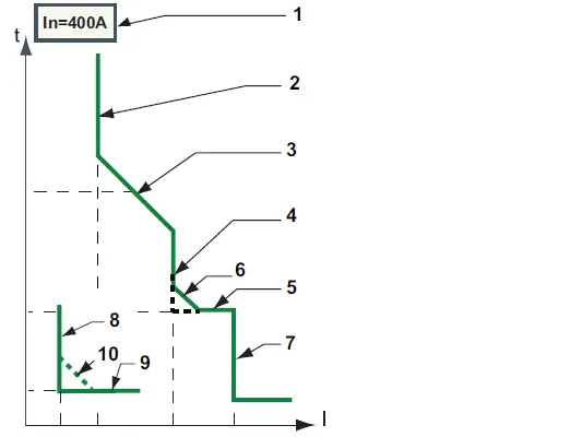
- A = Adjustable
- AR=Adjustable with RSU software
- N = Not Adjustable
- — = Not Available
| No | Function | MicroLogic Trip Unit | |
| 5.2 | 6.2 | ||
| 1 | In | N | N |
| 2 | Ir | A | A |
| 3 | tr | A | A |
| 4 | Isd | A | A |
| 5 | tsd | A | A |
| 6 | I2t ON/OFF | A | A |
| 7 | Ii | A | A |
| 8 | Ig | — | A |
| 9 | tg | — | A |
| 10 | I2t ON/OFF | — | A |
| Function | Description |
| In | Sensor rating |
| Ir | Long-time protection pickup |
| tr | Long-time protection time delay |
| Isd | Short-time protection pickup |
| tsd | Short-time protection time delay |
| I2t ON/OFF | Short-time protection I2t curve in ON or OFF position |
| Ii | Instantaneous protection pickup |
| Ig | Ground-fault protection pickup |
| tg | Ground-fault protection time delay |
| I2t ON/OFF | Ground-fault protection I2t curve in ON or OFF position |
Circuit Breaker Removal
- Turn off all power supplying this equipment before working on or inside equipment.
- Remove circuit breaker in reverse order of installation.
Troubleshooting
If problems occur during installation, refer to the following guide. If trouble persists, contact the local field office.
DANGER: HAZARD OF ELECTRIC SHOCK, EXPLOSION, OR ARC FLASH
- This equipment must be installed and serviced only by qualified electrical personnel.
- Troubleshooting may require energizing auxiliary devises with a test power supply. Make sure that the power supply is Off (O) before connecting or disconnecting it to the auxiliary device.
- Qualified persons performing diagnostics or troubleshooting that require electrical conductors to be energized must comply with NFPA 70 E – Standard for Electrical Safety Requirements for Employee Workplaces and OSHA Standards -29 CFR Part 1910 Subpart S -Electrical.
Failure to follow these instructions will result in death or serious injury.
| Condition | Possible Causes | Solution |
| Circuit breaker fails to stay closed. | Short circuit or overload on system. | Check system for short circuit or overload. |
| Circuit beaker trips, but no short circuit or overload is evident. | Voltage is below undervoltage trip setting. | Check system for low voltage. |
| Push-to-trip button does not trip circuit breaker. | Circuit breaker already tripped. | Move circuit breaker handle to reset then to on (I). |
| Circuit breaker cannot be opened manually. | Damage to current path. | Contact local field office. |
Electrical equipment must be installed, operated, serviced, and maintained only by qualified personnel. No responsibility is assumed by Schneider Electric for any consequences arising out of the use of this material.
Schneider Electric and Square D are trademarks and the property of Schneider Electric SE, its subsidiaries, and affiliated companies. All other trademarks are the property of their respective owners.
Schneider Electric Limited
Stafford Park 5
Telford TF3 3BL
United Kingdom
www.se.com/uk
Schneider Electric USA, Inc.
800 Federal Street
Andover, MA 01810 USA
888-778-2733
www.se.com/us
© 2011-2022 Schneider Electric All Rights Reserved
References
 P65Warnings.ca.gov
-
p65warnings.ca.gov/
 Schneider Electric Global | Global Specialist in Energy Management and Automation
-
Schneider Electric Canada | Global Specialist in Energy Management and Automation
-
Schneider Electric Mexico | Servicios de Renovación y Retrofit de Schneider Electric
-
Schneider Electric UK | Energy Management and Automation
-
Schneider Electric USA | Global Specialist in Energy Management and Automation
-
Schneider Electric Global | Global Specialist in Energy Management and Automation
-
Frequently Asked Questions - Schneider Electric


