
NOVAERUS NV900 Air Purifier

Intended Purpose
The intended purpose of the Novaerus Protect 900 (NV900) is to improve the quality of air.
Please read and follow all instructions in this manual.
Labeling Symbols
| Symbol | Meaning |
 | Caution, Consult User’s Manual |
 | Caution, High Voltage |
 | Date of Manufacture |
 | Manufactured for or by |
 | Serial Number |
 | This product has been tested by UL to nationally recognized safety and sustainability standards. |
 | On (Power) |
 | Off (Power) |
 | Slow Fan Speed (Speed 1) |
 | High Fan Speed (Speed 2) |
 | Accompanying documents must be consulted |
 | Indicates the temperature limits to which the medical device can be safely exposed. |
 | Indicates the range of humidity to which the medical device can be safely exposed. |
Classification of Equipment
| Item | Classification |
| Protection of Harmful Ingress of Water | IPX0 (No protection, indoor use only) |
| Mode of Operation | Continuous |
| Oxygen Rich Environments | Not intended for oxygen rich environments |
Warnings
General Warnings
- CAUTION: This High Voltage (HV) Device is not suitable for use within atmospheres that contain potentially combustible or explosive dusts, vapors or gases (including oxygen rich environments)
- CAUTION: This device should not be operated during environmental sterilization processes such as fogging and misting. Both the water vapor and chemical agents may cause internal damage to device componentry thus invalidating the warranty.
- CAUTION: This equipment contains high voltage.
- CAUTION: This equipment should be inspected frequently and collected dirt removed from it regularly to prevent excessive accumulation that may result in flashover or a risk of fire.
- CAUTION: To avoid the risk of electric shock, this equipment must only be connected to a supply main with protective earth.
- CAUTION: Do not restrict the airflow of the product.
- CAUTION: Do not open the tamper-proof screws on the casing of the unit. No serviceable parts are contained within.
- CAUTION: No modification of this equipment is allowed. Do not modify this equipment without the authorization of the manufacturer.
- CAUTION: Do not position the equipment where it is difficult to operate the power switch.
- CAUTION: For continued protection against the risk of fire, replace the fuse with the same type and rating, Listed, 120 Vac, 3 Amps.
- CAUTION: The non-detachable power supply cord is not fielded replaceable by service personnel. If damaged during inspection, the service should be immediately disconnected from power and returned to Novaerus.
- CAUTION: Do not use outdoors or near water.
- CAUTION: Not to be used by persons (including children) with reduced physical, sensory or mental capabilities, or lack of experience and knowledge, unless they have been given supervision or instruction.
- CAUTION: To reduce the risk of electric shock, this equipment has a grounding-type plug that has a third (grounding) pin. This plug will only fit into a grounding type power outlet. If the plug does not fit into the outlet, contact qualified personnel to install the proper outlet. Do not alter the plug in any way.
- CAUTION: Use of this equipment adjacent to or stacked with other equipment should be avoided because it could result in improper operation. If such use is necessary, this equipment and the other equipment should be observed to verify that they are operating normally.
- CAUTION: Portable RF communications equipment (including peripherals such as antenna cables and external antennas) should be used no closer than 12 inches (30 cm) to any part of the Protect 900, including cables specified by the manufacturer. Otherwise, degradation of the performance of this equipment could result.
Technical Specifications
Wall mountable, countertop with table stand or mounted on portable high tower stand, supplied with 6.6 ft power cord
- Electrical Rating:
Single Phase, 100-120 VAC, 60 Hz Fuse Rated at 120 VAC, 3 Amps, Listed - Power Consumption:
Maximum 14W - Construction and Color:
Precision-cut fabricated metal casing in a white anti-bacterial powder coat finish - Dimensions:
14.4″ (h) × 14.4″ (w) × 4.5″ (d) - Weight:
Approx. 10.4 lbs - Electrical Connection:
Switched and fused with a grounded, molded power cord
Accessories
Table or High-Tower Stand (Sold Separately).
Fan Air Flow Volume:
SPEED I: 129 CFM
SPEED II: 153 CFM
Noise Levels:
SPEED I: 40 dB
SPEED II: 45 dB
Operating Conditions:
50 – 95 °F, 10 – 75% Relative Humidity
Shipping / Storage Conditions:
41 – 122 °F, Maximum 95% Relative Humidity
Quality and Safety:
Manufactured under ISO 9001, ISO 14001 & OHSAS 18001
IEC 60601-1, Third Edition
IEC 60601-1-2, Fourth Edition
UL 867 Safety for Electrostatic Air Cleaners
Instructions for Use
The product should be placed in a dry location and connected to a suitable grounded outlet. The product is intended to be wall-mounted or placed on a stand. Please follow the wall mounting instructions included in this document. Once the product is installed, turn the power switch to the on position. The device is now operating and the blue light will be illuminated. The product includes a fan speed switch to allow the product to be set on a slow or high speed. Roman numeral I indicate slow speed, and Roman numeral II indicates high speed.
Wall Mounting Instructions
The mounting of this product shall be conducted by a person that is experienced with the proper use of standard installation tools such as a drill, screwdriver, tape measure and level. The unit should be installed approximately two third’s up the wall.
The product can be wall-mounted using suitable fasteners for the corresponding wall type. Fix the screws horizontally with a spacing of 7-1/8″ (180 mm). Leave the screw head protruding no more than 0.5″ (12 mm) from the wall for hanging. Ensure screws are tightly secured into the wall and a solid connection is made between the screws and the unit. Ensure the product is level. Follow these instructions depending upon the mounting surface:
Hollow Wall Construction
For hollow wall installations studded with metal or wood framing and sheathed with drywall, plaster, or plywood, an appropriate hollow wall fixing such as a #10 re-usable anchor should be used.
Each of the two re-usable anchors used must be rated for a 20.0 lb. (9.1 kg) rating minimum, and be the appropriate size for the sheathing thickness. Use #10 size minimum.
The typical drill size is 3/8″ (9.5 mm) for the #10 re-usable anchor shown. Follow manufacturer’s instructions.
For Concrete or Masonry Wall Construction
Use purposed 3/16″ (4. 8 mm) concrete screws.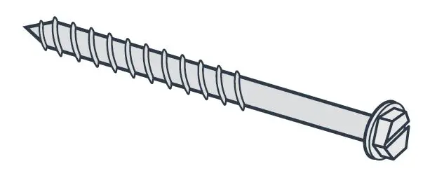
Each of the two screws must be rated for 20.0 lb (9.1 kg) minimum.
The typical drill size is 5/32″ (4 mm) for the 3/16″ (4.8 mm) concrete screw. Follow manufacturer’s instructions and recommendation for drill depth for screws being used. Various types of concrete inserts are available that are adequate for use in concrete, such as conical lead or flanged polypropylene that will be adequate for installation of the rack mount bracket. They must be individually rated to support 20.0 lb (9.1 kg) minimum.
Use sizes that support a #10 screw minimum.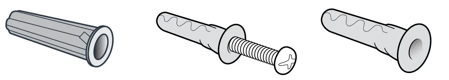
Typical drill size is 5/16″ (8 mm) for the #10 conical lead anchor for concrete. Follow manufacturer’s instructions and recommendation for drill depth for insert being used.
Typical drill size is 1/4″ (6.35 mm) for the #10 flanged polypropylene anchor for concrete. Follow manufacturer’s instructions and recommendation for drill depth for insert being used.
For Plywood Wall Construction
Use #10 1″ (25 mm) screw. Each of the two screws must be rated for 20.0 lb (9.1 kg) minimum.
Service and Maintenance Instructions
Clean the body of the Protect 900 regularly to prevent dust from collecting.
- Wipe away dust from the body of the device with a soft dry cloth.
- Clean the air outlet with a soft dry cloth.
Air Intake Screen
Cleaning of the air intake screen is recommended monthly. To clean the air intake screen, use a standard vacuum cleaner brush or compressed air in an open ventilated area to blow the dust off the screen.
Use a bowl of soapy water to hand wash the scrim. While wearing gloves, remove the scrim and soak for 5 minutes. Pat dry before replacing the scrim and dispose of gloves.
It is recommended that the user inspect the air intake screen bi-weekly in the first 2 months of use to determine the most appropriate cleaning period for its facility. If dust and debris has collected on the intake screen sufficient enough to cause a significant decrease in airflow, more frequent cleaning may be required.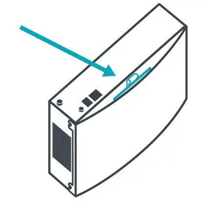
The air intake screen can be removed by pulling on the cloth tab attached to the screen frame. The air intake screen is removed from the top of the device. See image with arrow indicating location of screen tab.
Replacing the screen
When replacing the screen, please ensure that the screen is pushed down in the track completely to ensure the air intake is completely covered by the screen. You will feel the screen stop once it is fully inserted; no part of the screen frame should be sticking out from the top of the unit.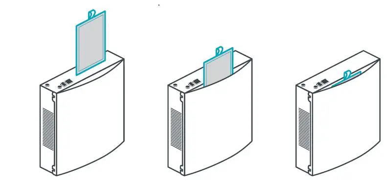
The metal frame grid should be facing towards the rear of device as shown in the image below.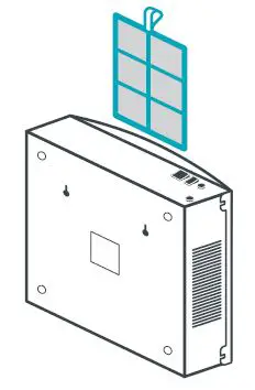
An additional screen has been provided for each unit to allow for rotation during the cleaning process. The Protect 900 unit should not be operated without the air intake screen in place.
Service
Do not open the tamper-proof screws on the casing of the unit. No serviceable parts are contained within. The units should be opened by qualified Novaerus personnel only.
Troubleshooting
Should the unit sustain severe damage and an increase in noise from the internal parts is observed, discontinue use of the unit and contact a representative of the Novaerus technical team for assistance? This product is not intended to be repaired in the field.
Should the unit not power on, or the fan stops working, check to ensure that the fuse located on top of the unit is secured tightly in its socket. If, once the fuse is replaced and the unit or fan does not turn on, immediately discontinue use.
Product Certifications
IEC 60601-1, Third Edition
IEC 60601-1-2, Fourth Edition
UL 867 Safety for Electrostatic Air Cleaners
APPENDIX A. Guidance and Manufacturer’s Declarations
Table 201: Guidance and manufacturer’s declaration – electromagnetic emissions – for all equipment and systems
| Guidance and manufacturer’s declaration – electromagnetic immunity | ||
| The Protect 900 is intended for use in the electromagnetic environment specified below. The customer or the user of the Protect 900 should assure that it is used in such an environment. | ||
| Emissions test | Compliance | |
| RF Emissions CISPR 11 EN 55011: 2009 + A1: 2010 |
Group 1 | The Protect 900 must emit electromagnetic energy in order to perform its intended function. Nearby electronic equipment may be affected. |
| RF Emissions CISPR 11 EN 55011 | Class B | The Protect 900 is suitable for use in all establishments including domestic and those directly connected to the public low-voltage power supply network that supplies buildings used for domestic purposes. |
| Harmonic emissions EN 61000-3-2 | Complied | |
| Voltage fluctuations / flicker emissions EN 61000-3-3 | Complied | |
Table 202: Guidance and manufacturer’s declaration – electromagnetic immunity – for all equipment and systems
| Guidance and manufacturer’s declaration – electromagnetic immunity | |||
| The Protect 900 is intended for use in the electromagnetic environment specified below. The customer or the user of the Protect 900 should assure that it is used in such an environment. | |||
| Immunity test | IEC 60601 Test level | Compliance level | Electromagnetic environment – guidance |
| Electrostatic discharge (ESD) EN 61000- 4-2 | +/- 8 kV contact +/- 15 kV air | +/- 2, 4, 6 & 8 kV contact +/- 2, 4, 8 & 15 kV air | Floors should be wood, concrete or ceramic tile. If floors are covered with synthetic material, the relative humidity should be at least 30%. |
| Electrical fast transient/ burst EN 61000- 4-4 | +/- 2kV for power supply lines +/-1 kV for input/ output lines | +/- 2kV for power supply lines +/- 1kV for input/ output lines | Mains power quality should be that of a typical commercial or hospital environment. |
|
Surge EN 61000-4-5 | +/- 1kV differential mode +/- 2 kV common mode | +/- 0.5 & 1kV differential mode +/- 0.5, 1 & 2 kV common mode | Mains power quality should be that of a typical commercial or hospital environment. |
| Voltage dips, short interruptions and voltage variations on power supply input lines EN 61000- 4-11 | <5 % Ut (>95 % dip in Ut) for 0.5 cycle @ 0°, 45°, 90°, 135°, 180°, 225°, 270°, 315° 70 % Ut (30 % dip in Ut) for 25 cycles <5 % Ut (>95 % dip in Ut) for 5 sec | <5 % Ut (>95 % dip in Ut) for 0.5 cycle @ 0°, 45°, 90°, 135°, 180°, 225°, 270°, 315° 70 % Ut (30 % dip in Ut) for 25 cycles <5 % Ut (>95 % dip in Ut) for 5 sec | Mains power quality should be that of a typical commercial or hospital environment. If the user of the Protect 900 requires continued operation during power mains operation, it is recommended that the Protect 900 be powered from an uninterruptible power supply or battery. |
| Power frequency (50/60 Hz) magnetic field EN 61000- 4-8 |
30 A/m |
30 A/m | Power frequency magnetic fields should be at levels characteristic of a typical location in a typical commercial or hospital environment. |
| NOTE: Ut is the a.c.mains voltage prior to application of the test level. | |||
Table 203: Guidance and manufacturer’s declaration – electromagnetic immunity – for equipment and systems that are not life-supporting
| Guidance and manufacturer’s declaration – electromagnetic immunity | |||
| The Protect 900 is intended for use in the electromagnetic environment specified below. The customer or the user of the Protect 900 should assure that it is used in such an environment. | |||
| Immunity Test | IEC 60601 Test Level | Compliance Level | Electromagnetic environment – guidance |
| Conducted RF EN 61000- 4-6 Radiated RF EN 61000-4-3 | 3 Vrms outside industrial, scientific and medical (ISM) and amateur radio bands. 6 Vrms in ISM and amateur radio bands 150 kHz to 80 MHz 10 V/m 80 MHz to 2.7 GHz 27 V/m, 18 Hz PM 385 MHz 28 V/m, 50 %18 Hz PM 450 MHz 9 V/m, 217 Hz PM 710 MHz 9 V/m, 217 Hz PM 745 MHz 9 V/m, 217 Hz PM 780 MHz 28V/m, 18 Hz PM 810 MHz 28 V/m, 18 Hz PM 870 MHz 28 V/m, 18 Hz PM 930 MHz 28V/m, 217 Hz PM 1720 MHz 28 V/m, 217 Hz PM 1845 MHz | 6 Vrms 150 kHz to 80 MHz 150 kHz to 80 MHz 10 V/m 80 MHz to 2.7 GHz 27 V/m, 18 Hz PM 385 MHz 28 V/m, 50 %18 Hz PM 450 MHz 9V/m,217HzPM 710 MHz 9V/m,217HzPM 745 MHz 9V/m,217HzPM 780 MHz 28V/m, 18 Hz PM 810 MHz 28V/m,18HzPM 870 MHz 28V/m,18HzPM 930 MHz 28V/m, 217 Hz PM 1720 MHz 28 V/m, 217 Hz PM 1845 MHz 28 V/m, 217 Hz PM 1970 MHz 27 V/m, 217 Hz PM 2450 MHz | Portable and mobile RF communications equipment should be used no closer to any part of the Protect 900, including cables, than the recommended separation distance calculated from the equation applicable to the frequency of the transmitter. Recommended separation distance d = [1.17] Sqrt P d = [1.17] Sqrt P…80MHz to 800 MHz d = [2.33] Sqrt P…800 MHz to 2.5GHz. Where P is the maximum output power rating of the transmitter in Watts (W), according to the transmitter manufacturer, and d is the recommended separation distance in meters (m), field strengths from fixed RF transmitters, as determined by an electromagnetic site survey a, should be less |
| 28 V/m, 217 Hz PM 1970 MHz 9V/m, 217 Hz PM 5240 MHz 9 V/m, 217 Hz PM 5500 MHz 9 V/m, 217 Hz PM 5785 MHz | 5240 MHz 9 V/m, 217 Hz PM 5500 MHz 9 V/m, 217 Hz PM 5785 MHz | than the compliance level in each frequency range b. Interference may occur in the vicinity of equipment marked with the following symbol: | |
| NOTE 1: At 80 MHz and 800 MHz, the higher frequency range applies. NOTE 2: These guidelines may not apply in all situations. Electromagnetic propagation is affected by absorption and reflection from structures, objects and people. | |||
| a. Field strengths from fixed transmitters, such as base stations for radio (cellular/cordless) telephones and land mobile radios, amateur radio, AM and FM radio broadcast and TV broadcast cannot be predicted theoretically with accuracy. To assess the electromagnetic environment due to fixed RF transmitters, an electromagnetic site survey should be considered. If the measured field strength in the location in which the Protect 900 is used exceeds the applicable RF compliance level above, the Protect 900 should be observed to verify normal operation. If abnormal performance is observed, additional measures may be necessary, such as re-orientating or relocating the Protect 900. b. Over the frequency range 150 kHz to 80 MHz, field strengths should be less than [V1]V/m. | |||
Table 204: Recommended separation distances between portable and mobile RF communications equipment and the equipment and system – for equipment and systems that are not life-supporting
| Recommended separation distances between portable and mobile RF communication equipment and the Protect 900. | |||
| The Protect 900 is intended for use in an electromagnetic environment in which radiated RF disturbances are controlled. The customer or the user of the Protect 900 can help prevent electromagnetic interference by maintaining a minimum distance between portable and mobile RF communications equipment (transmitters) and the Protect 900 as recommended below, according to the maximum output power of the communications equipment. | |||
| Rated maximum output power of transmitter W | Separation distance according to frequency of transmitter m | ||
| 150 kHz to 80 MHz d = [1.17] Sqrt P | 80 MHz to 800 MHz d = [1.17] Sqrt P | 800 MHz to 2.5GHz d = [2.33] Sqrt P | |
| 0.01 | 0.12 | 0.12 | 0.23 |
| 0.1 | 0.37 | 0.37 | 0.75 |
| 1 | 1.17 | 1.17 | 2.33 |
| 10 | 3.70 | 3.70 | 7.36 |
| 100 | 11.70 | 11.70 | 23.30 |
| For transmitters rated at a maximum output power not listed above, the recommended separation distance d in meters (m) can be estimated using the equation applicable to the frequency of the transmitter, where P is the maximum output power rating of the transmitter in watts (w) according to the transmitter manufacturer.
NOTE 1 At 80 MHz and 800 MHz, the separation distance for the higher frequency range applies. NOTE 2 These guidelines may not apply in all situations. Electromagnetic propagation is affected by absorption and reflection from structures, objects and people. | |||


