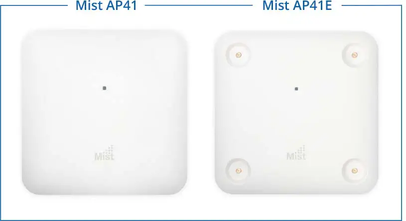
Mist AP41 Access Point
Overview
The Mist AP41 delivers 4×4 MIMO with four spatial streams when operating in multi-user (MU) or single-user (SU) mode that supports the IEEE 802.11ac Wave 2 specification.
I/O ports and Kensington lock
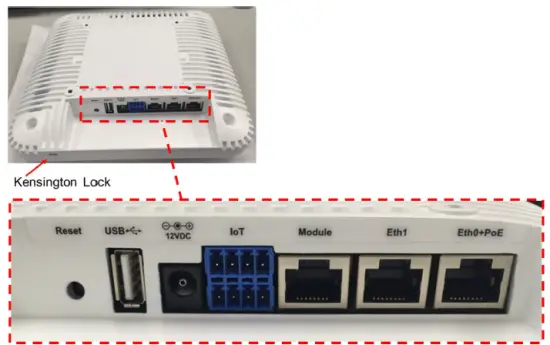
| Reset | Reset to the factory default settings |
| USB | USB2.0 support interface |
| 12VDC | Support for the 12VDC power supply recommended by Mist |
| IoT | 8-pin interface for digital input, digital output, analog input, and ground |
| Module | 10/100/1000 BaseT RJ45 interface |
| Eth1 | 10/100/1000 BaseT RJ45 interface |
| Eth0+PoE | 10/100/1000 BaseT RJ45 interface that supports 802.3at PoE PD |
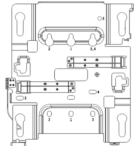
AP41 Mounting
In a wall mount installation, please use screws that have a 1/4in. (6.3mm) diameter head with a length at least 2 in. (50.8mm). 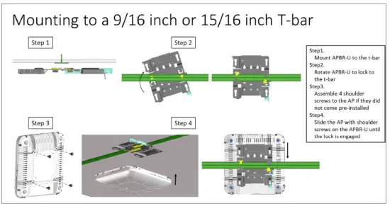
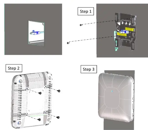
US SINGEL GANG,3.5 OR 4 INCH ROUND JUNCTION BOX
- Step 1 Mount APBR-U to the box using two screws and the #1 holes. Make sure the Ethernet cable extends thru the bracket.
- Step 2 Assemble 4 shoulder screws to the AP if they did not come pre-installed
- Step 3 Slide the AP with shoulder screws on the APBR-U until the lock is engaged
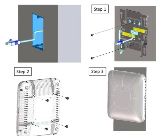
US double-gang junction box
- Step 1 Mount APBR-U to the box using two screws and the #2 holes. Make sure the Ethernet cable extends thru the bracket.
- Step 2 Assemble 4 shoulder screws to the AP if they did not come pre-installed
- Step 3 Slide the AP with shoulder screws on the APBR-U until the lock is engaged
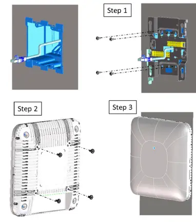
US 4 inch square junction box
- Step 1 Mount APBR-U to the box using two screws and the #3 holes. Make sure Ethernet cable extends thru the bracket.
- Step 2 Assemble 4 shoulder screws to the AP if they did not come pre-installed
- Step 3 Slide the AP with shoulder screws on the APBR-U until the lock is engaged
EU junction box
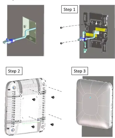
- Step 1 Mount APBR-U to the box using two screws and the #4 holes. Make sure the Ethernet cable extends thru the bracket.
- Step 2 Assemble 4 shoulder screws to the AP if they did not come pre-installed
- Step 3 Slide the AP with shoulder screws on the APBR-U until the lock is engaged
Recessed 15/16 inch T-bar
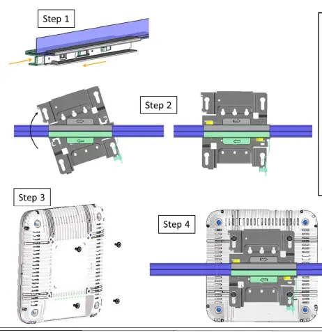
- Step 1 Mount the APBR-ADP-RT15 to the t -bar
- Step 2 Mount the APBR-U to the APBR-ADP-RT15. Rotate the APBR-U to lock to the APBRADP- RT15
- Step 3 Assemble 4 shoulder screws to the AP if they did not come pre-installed
- Step 4 Slide the AP with shoulder screws on the APBR-U until the lock is engaged
Recessed 9/16 inch T-bar or channel rail
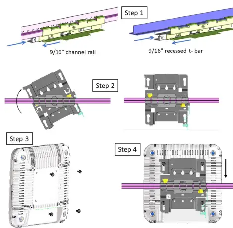
- Step 1 Mount the APBR-ADP-CR9 to the t-bar
- Step 2 Mount the APBR-U to the APBR-ADP-CR9. Rotate the APBR-U to lock to the APBR-ADP-CR9
- Step 3 Assemble 4 shoulder screws to the AP if they did not come pre-installed
- Step 4 Slide the AP with shoulder screws on the APBR-U until the lock is engaged
1.5 inch T-bar
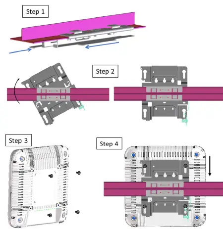
- Step 1 Mount the APBR-ADP-WSS to the t -bar
- Step 2 Mount the APBR-U to the APBR-ADP-WSlS. Rotate the APBR-U to lock to the APBR-ADP-WSS
- Step 3 Assemble 4 shoulder screws to the AP if they did not come pre-installed
Step 4 Slide the AP with shoulder screws on the APBR-U until the lock is engaged
Mounting to a 5/8 inch threaded rod
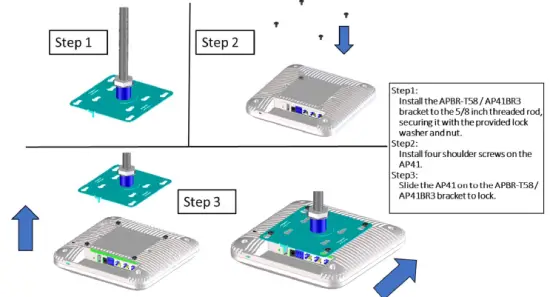
- Step 1: Install the APBR-T58 / AP41BR3 bracket to the 5/8 inch threaded rod, securing it with the provided lock washer and nut.
- Step 2: Install four shoulder screws on the AP41.
- Step3: SI ide the AP41 on to the APBR-T58/ AP41BR3 bracket to lock.
Mounting to a 16mm threaded rod .,
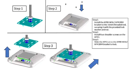
- Step 1: Install the APBR-M16 / AP41BR4 bracket to the 16mmthreaded rod, securing it with the provided lock washer and nut.
- Step 2: Install four shoulder screws on the AP41.
- Step3: Slide the AP41on to the APBR-M16/ AP41BR4 bracket to lock.
Technical Specifications:
| Feature | Description |
| Power options | 802.3at PoE 12V/3A DC power supply |
| Powering adaptor | 100-240VAC, 50-60 Hz, input All regions (output): 12V/3A DC output |
| Dimensions | 215mm x 215mm x 52mm (8.46in x 8.46in x 2.05in) |
| Weight | 1.6 kg (3.53 lbs) |
| Operating temperature | Internal antenna 0° to 40° C External antenna -20° to 50° C |
| Operating humidity | 10% to 90% maximum relative humidity, non-condensing |
| Operating altitude | 3,048m (10,000 ft) |
| Electromagnetic emissions | FCC Part 15 Class B |
|
I/O | 1 – 10/100/1000BASE-T auto-sensing RJ-45 with PoE 1 – 10/100/1000BASE-T auto-sensing RJ-45 1 – 10/100/1000BASE-T auto-sensing RJ-45 USB2.0 IoT terminal block 12VDC |
|
RF | 2.4GHz – 4×4:4 spatial streams 802.11ac MU-MIMO & SU-MIMO 5GHz – 4×4:4 spatial streams 802.11ac MU-MIMO & SU-MIMO 2.4GHz / 5GHz scanning radio 2.4GHz BLE with Dynamic Antenna Array |
| Maximum PHY rate | Total maximum PHY rate – 2533Mbps 5GHz – 1733 Mbps 2.4GHz – 800Mbps |
| Indicators | Multi-color status LED |
| UL 60950-1 & CAN/CSA-C22.2 No. 60950-1 | |
| UL 2043 | |
| FCC Part 15.247, 15.407, 15.107, and 15.109 | |
| RSS-247 & ICES-003 (Canada) | |
| EN 301 489-1 V2.1.1 | |
| Compliance standards | EN 301 489-17 V3.1.1 EN 300 328 V2.1.1 |
| EN 301 893 V2.1.1 | |
| EN 50385: 2002 | |
| IEC/EN 60950-1:2006 + A11:2009 + A1:2010 + A12:2011 + | |
| A2:2013 | |
| EN 55032:2015 + AC:2016, Class B |
Suitable for use in environmental air space in accordance with Section 300-22(C) of the National Electrical Code, and Sections 2-128, 12-010(3), and 12-100 of the Canadian Electrical Code, Part 1, CSA C22.1.
Warning: The AP must be mounted only horizontally if you mount it into a plenum space.
Warranty Information
The AP41 family of Access Points comes with a limited lifetime warranty.
Ordering Information:
Access Points
| AP41-US | Premium Wi-Fi & BLE Array AP with internal antennas for the US Regulatory domain |
| AP41E-US | Premium Wi-Fi & BLE Array AP with external antenna connectors for the US Regulatory domain |
| AP41-WW | Premium Wi-Fi & BLE Array AP with internal antennas for the WW Regulatory domain |
| AP41E-WW | Premium Wi-Fi & BLE Array AP with external antenna connectors for the WW Regulatory domain |
Mounting brackets
| APBR-U | Universal AP Bracket for T-Rail and Drywall mounting for Indoor Access Points |
| AP41BR1 | Premium AP T-bar ceiling mounting bracket kit |
| AP41BR2 | Premium AP drywall ceiling mounting bracket kit |
| APBR-T58 / AP41BR3 | 5/8-inch threaded rod bracket |
| APBR-M16 / AP41BR4 | 16mm threaded rod bracket |
| APBR-ADP-CR9 / AP41BR1-CR | Adapter for channel rail and recessed 9/16” trail |
| APBR-ADP-RT15 / AP41BR1-RT | Adapter for recessed 15/16″ trail |
| APBR-ADP-WS15 | Adapter for recessed 1.5″ trail |
Power Supply options
- DC-01: 100-240VAC, 50-60 Hz, input All regions (output): 12V/3A DC output
This product is intended to be supplied by an approved limited power source (adapter label marked with L.P.S. or LPS) with an output rated 12Vdc/3A minimum or 50-57Vdc/600mA minimum which has an operating temperature range of 50C and operating altitude of 3,048 meters.
If using a class I adapter/power injector, the power cord needs to be connected to the outlet utilizing the ground pin.
Antennas
| M6060060MP1D43620 | Ventev Patch Antenna, 6dBi/6dBi (2.4GHz/5GHz) |
| PDQ24518-MI1 | Laird Patch Antenna 8dBi/8dBi (2.4GHz/5GHz) |
Regulatory Compliance Information:
This product and all interconnected equipment must be installed indoors within the same building, including the associated LAN connections as defined by the 802.3at Standard.
Operations in the 5.15GHz – 5.35GHz band are restricted to indoor usage only.
If you need further assistance with purchasing the power source, please contact Mist Systems, Inc.
FCC Requirement for Operation in the United States of America:
FCC Guideline for Human Exposure
This equipment complies with FCC radiation exposure limits set forth for an uncontrolled environment. This equipment should be installed and operated with a minimum distance 35cm between the radiator & your body.
This device complies with Part 15 of the FCC Rules. Operation is subject to the following two conditions: (1) This device may not cause harmful interference, and (2) this device must accept any interference received, including interference that may cause undesired operation.
This equipment has been tested and found to comply with the limits for a Class B digital device, pursuant to Part 15 of the FCC Rules. These limits are designed to provide reasonable protection against harmful interference in a residential installation. This equipment generates, uses and can radiate radio frequency energy and, if not installed and used in accordance with the instructions, may cause harmful interference to radio communications. However, there is no guarantee that interference will not occur in a particular installation. If this equipment does cause harmful interference to radio or television reception, which can be determined by turning the equipment off and on, the user is encouraged to try to correct the interference by one of the following measures:
- Reorient or relocate the receiving antenna.
- Increase the separation between the equipment and receiver.
- Connect the equipment into an outlet on a circuit different from that to which the receiver is connected.
- Consult the dealer or an experienced radio/TV technician for help.
FCC Caution
- Any changes or modifications not expressly approved by the party responsible for compliance could void the user’s authority to operate this equipment.
- This transmitter must not be co-located or operating in conjunction with any other antenna or transmitter.
- For operation within 5.15 ~ 5.25GHz / 5.47 ~5.725GHz frequency range, it is restricted to the indoor environment.
Industry Canada
This device complies with RSS-247 of the Industry Canada Rules. Operation is subject to the following two conditions: (1) This device may not cause harmful interference, and (2) this device must accept any interference received, including interference that may cause undesired operation.
Ce dispositif est conforme à la norme CNR-247 d’Industrie Canada applicable aux appareils radio exempts de licence. Son fonctionnement est sujet aux deux conditions suivantes: (1) le dispositif ne doit pas produire de brouillage préjudiciable, et (2) ce dispositif doit accepter tout brouillage reçu, y compris un brouillage susceptible de provoquer un fonctionnement indésirable.
Radiation Exposure Statement:
This equipment complies with IC radiation exposure limits set forth for an uncontrolled environment. This equipment should be installed and operated with minimum distance 44cm between the radiator & your body.
Déclaration d’exposition aux radiations:Cet équipement est conforme aux limites d’exposition aux rayonnements IC établies pour un environnement non contrôlé. Cet équipement doit être installé et utilisé avec un minimum de 44 cm de distance entre la source de rayonnement et votre corps.
IC Caution
- (i) The device for operation in the band 5150-5250 MHz is only for indoor use to reduce the potential for harmful interference to co-channel mobile satellite systems;
- (ii) The maximum antenna gain permitted for devices in the bands 5250-5350 MHz and 5470-5725 MHz shall be such that the equipment still complies with the e.i.r.p. limit;
- (iii) The maximum antenna gain permitted for devices in the band 5725-5850 MHz shall be such that the equipment still complies with the e.i.r.p. limits specified for point-to-point and non-point-to-point operation as appropriate; and
- (iv) Users should also be advised that high-power radars are allocated as primary users (i.e. priority users) of the bands 5250-5350 MHz and 5650-5850 MHz and that these radars could cause interference and/or damage to LE-LAN devices.
CE
This device complies with the Radio Equipment Directive, 2014/53/EU, issued by the Commission of the European Community.
Hereby, Mist Systems, Inc. declares that the radio equipment type (AP41) is in compliance with Directive 2014/53/EU.
The full text of the EU declaration of conformity is available at the following: https://www.mist.com/support/
The frequency and maximum EIRP Power in EU:
Bluetooth:
| Frequency range (MHz) | Maximum EIRP in EU (dBm) |
| 2400 – 2483.5 | 9.43 |
WLAN:
| Frequency range (MHz) | Maximum EIRP in EU (dBm) |
| 2400 – 2483.5 | 19.84 |
| 5150 – 5250 | 22.90 |
| 5250 – 5350 | 22.68 |
| 5500 – 5700 | 29.62 |


