Mist AP63 Premium Outdoor Hardware
Overview
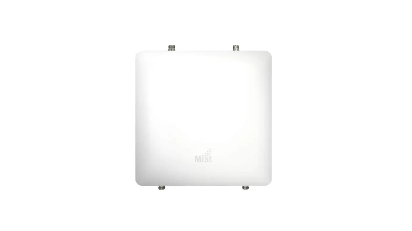
The Mist AP63 is an IP67-rated outdoor access point that contains three IEEE 802.11ax radios that deliver 4×4 MIMO with four spatial streams when operating in multi-user (MU) or single-user (SU) mode.
I/O ports 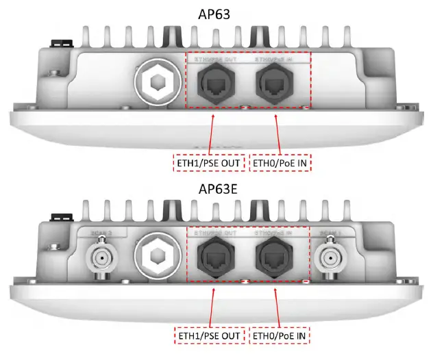
| ETH0/PoE IN | 100/1000/2500BASE-T RJ45 interface that supports 802.3at/802.3bt PoE PD |
| ETH1/PSE OUT | 10/100/1000BASE-T RJ45 interface + 802.3af PSE (if PoE IN is 802.3bt) |
AP63 Mounting Kit
Flush Mount Bracket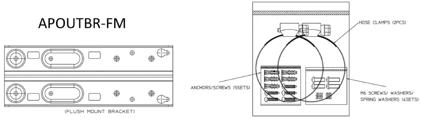
Articulating Mount Bracket 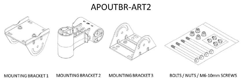
Flush Mount to Surface
Step 1
Drill 4 holes into the surface and insert the 2 upper screws. Tighten halfway into the surface
Step 2
Install the APOUTBR-FM onto the AP63
Step 3
Install the AP63 with bracket onto the wall using the keyholes on the bracket
Step 4
Install the final 2 screws and tighten all into the Surface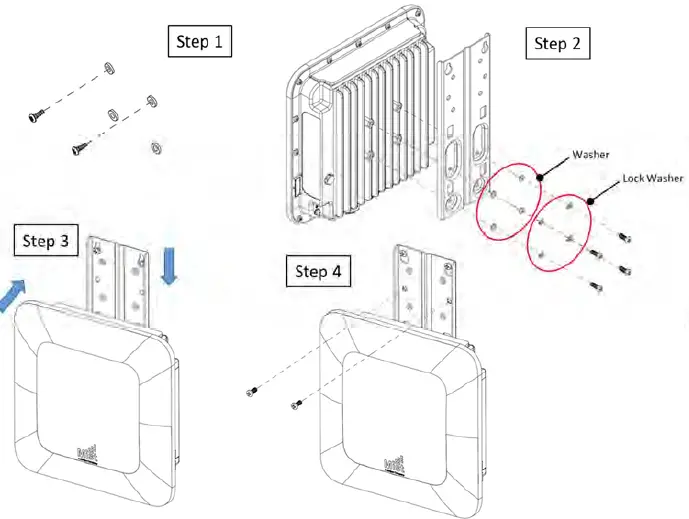
Flush Mount to Pole
Step 1
Install the hose clamps onto the APOUTBR-FM.
Step 2
Install the APOUTBR-FM onto the AP63
Step 3
Install the AP63 with a bracket to the pole
Step 4
Tighten the hose clamp screw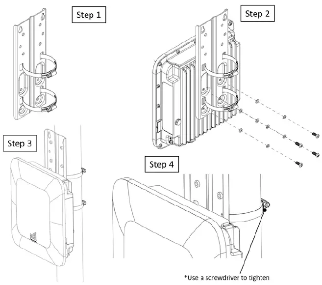
Articulating Mount to Surface
Step 1
Install the APOUTBR-FM to the AP63
Step 2
Install the APOUTBR-ART2 Mounting Bracket3 to the APOUTBR-FM
Step 3
Disassemble APOUTBR-ART2 Mounting Bracket1
Step 4
Install APOUTBR-ART2 Mounting Bracket1 to the surface
Step 5
Assemble APOUTBR-ART2 Mounting Bracket2 to Bracket1. Attach the side with “E UP” to Bracket1
Step 6
Complete assembling the final parts together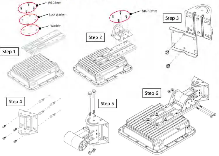
Articulating Mount to Pole
Step 1
Install the APOUTBR-FM to the AP63
Step 2
Install the APOUTBR-ART2 Mounting Bracket3 to the APOUTBR-FM
Step 3
Install APOUTBR-ART2 Mounting Bracket1 to the pole
Step 4
Assemble APOUTBR-ART2 Mounting Bracket2 to Bracket1. Attach the side with “E UP >” to Bracket1
Step 5
Complete assembling the final parts together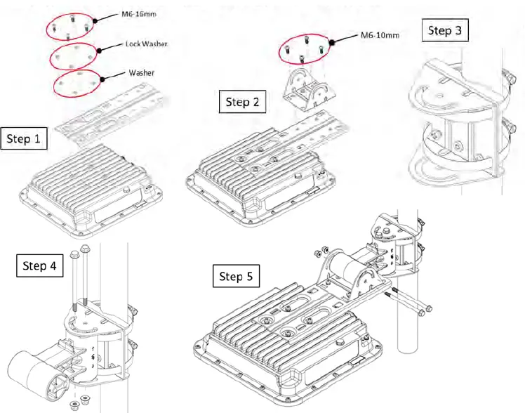
Connecting RJ45 Cable Gland
Step 1
Disassemble cable gland
Step 2
Remove the blue seal from the cable gland. Select the proper seal Blue seal diameter is 7mm-9.5mm Red seal diameter is 5.5mm- 7mm
Step 3
Open the seal and insert the Ethernet cable thru the nut and seal
Step 4
Push Ethernet cable thru the gland. ush the seal into the gland and loosely tighten the nut
Step 5
Connect the RJ45, tighten the cable gland to the AP63 meeting a torque spec of 10-12kg-cm, and fully tighten the nut to the cable gland meeting a torque spec of 7-10kg-cm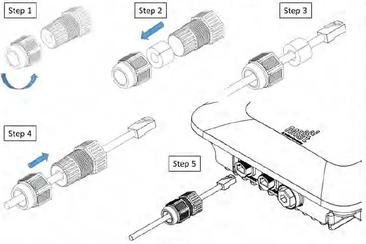
Technical Specifications
| Feature | Description |
| Power options | 802.3at/802.3bt PoE |
| Dimensions | 285mm x 285mm x 85mm (11.2in x 11.2in x 3.3in) |
| Weight | AP63: 3.4 kg (7.48 lbs) AP63E: 3.9 kg (8.58 lbs) |
| Operating temperature | AP63 / AP63E : -40° to 65° C without solar loading AP63 / AP63E: -40° to 55° C with solar loading |
| Operating humidity | 10% to 90% maximum relative humidity, non-condensing |
| Operating altitude | 3,048m (10,000 ft) |
| Water and Dust | IP67 |
| Electromagnetic emissions | FCC Part 15 Class B |
| I/O | 1 – 100/1000/2500BASE-T auto-sensing RJ-45 with PoE 1 – 10/100/1000BASE-T auto-sensing RJ-45 with PoE out |
| RF | 2.4GHz or 5GHz – 4×4:4SS 802.11ax MU-MIMO & SU-MIMO 5GHz – 4×4:4SS 802.11ax MU-MIMO & SU-MIMO 2.4GHz / 5GHz scanning radio 2.4GHz BLE with Dynamic Antenna Array |
| Maximum PHY rate | Total maximum PHY rate – 4800 Mbps 5GHz – 2400 Mbps 2.4GHz or 5GHz – 1148 Mbps or 2400Mbps |
| Indicators | Multi-color status LED |
| Wind Loading | 60 meters/second |
|
Compliance standards |
UL 62368-1 CAN/CSA-C22.2 No. 62368-1-14 FCC Part 15.247, 15.407, 15.107, and 15.109 RSS-247 ICES-003 (Canada) |
Warranty Information
The AP63 family of Access Points come with a 1 year limited warranty.
Ordering Information:
Access Points
| AP63-US | 802.11ax 4+4 Outdoor and BLE AP – Internal Antenna for the US Regulatory domain |
| AP63E-US | 802.11ax 4+4 Outdoor and BLE AP – External Antenna for the US Regulatory domain |
| AP63-WW | 802.11ax 4+4 Outdoor and BLE AP – Internal Antenna for the WW Regulatory domain |
| AP63E-WW | 802.11ax 4+4 Outdoor and BLE AP – External Antenna for the WW Regulatory domain |
Mounting brackets
| APOUTBR-KIT | APOUTBR-FM and APOUTBR-ART2 |
| APOUTBR-FM | Flush mount for Outdoor AP |
| APOUTBR-ART2 | Articulating mount for Outdoor AP |
Regulatory Compliance Information:
If you need further assistance with purchasing the power source, please contact Juniper Networks, Inc.
FCC Requirement for Operation in the United States of America:
FCC Guideline for Human Exposure
This equipment complies with FCC radiation exposure limits set forth for an uncontrolled environment. This equipment should be installed and operated with a minimum distance of 31 cm between the radiator & your body.
This device complies with Part 15 of the FCC Rules. Operation is subject to the following two conditions: (1) This device may not cause harmful interference, and (2) this device must accept any interference received, including interference that may cause undesired operation.
This equipment has been tested and found to comply with the limits for a Class B digital device, pursuant to Part 15 of the FCC Rules. These limits are designed to provide reasonable protection against harmful interference in a residential installation. This equipment generates, uses, and can radiate radio frequency energy and, if not installed and used in accordance with the instructions, may cause harmful interference to radio communications. However, there is no guarantee that interference will not occur in a particular installation. If this equipment does cause harmful interference to radio or television reception, which can be determined by turning the equipment off and on, the user is encouraged to try to correct the interference by one of the following measures:
- Reorient or relocate the receiving antenna.
- Increase the separation between the equipment and receiver.
- Connect the equipment into an outlet on a circuit different from that to which the receiver is connected.
- Consult the dealer or an experienced radio/TV technician for help.
FCC Caution
- Any changes or modifications not expressly approved by the party responsible for compliance could void the user’s authority to operate this equipment.
- This transmitter must not be co-located or operating in conjunction with any other antenna or transmitter.
- It must be Professionally installed.
Industry Canada
This device complies with RSS-247 of the Industry Canada Rules. Operation is subject to the following two conditions: (1) This device may not cause harmful interference, and (2) this device must accept any interference received, including interference that may cause undesired operation. Ce dispositif est conforme à la norme CNR-247 d’Industrie Canada applicable aux appareils radio exempts de licence. Son fonctionnement est sujet aux deux conditions suivantes: (1) le dispositif ne doit pas produire de brouillage préjudiciable, et (2) ce dispositif doit accepter tout brouillage reçu, y compris un brouillage susceptible de provoquer un fonctionnement indésirable.
Radiation Exposure Statement:
This equipment complies with IC radiation exposure limits set forth for an uncontrolled environment. This equipment should be installed and operated with minimum distance 36 cm between the radiator & your body. Déclaration d’exposition aux radiations:Cet équipement est conforme aux limites d’exposition aux rayonnements IC établies pour un environnement non contrôlé. Cet équipement doit être installé et utilisé avec un minimum de 36 cm de distance entre la source de rayonnement et votre corps.
IC Caution
This radio transmitter (IC: 22068-AP63 / Model: AP63, AP63E) has been approved by Innovation, Science, and Economic Development Canada to operate with the antenna types listed below, with the maximum permissible gain indicated. Antenna types not included in this list that have a gain greater than the maximum gain indicated for any type listed are strictly prohibited for use with this device.
Approved antenna(s) list:
AP63:
| Ant | Brand | Model Name | Antenna Type | Antenna Gain (dBi) | Radio | ||
| WLAN 2.4GHz | WLAN 5GHz | Bluetooth | |||||
| 1 ~ 4 | Juniper | 81XKAF15,G35 | PIFA | – | 6 | – | 5GHz |
| 5 ~ 8 | Juniper | 81XKAF15,G35 | PIFA | 4 | – | – | 2.4GHz |
| 9 | Juniper | 81XKAF15,G35 | PIFA | 2.3 | 4.7 | – | 2.4GHz/5GHz |
| 10 | Juniper | 81XKAF15,G35 | PIFA | 2.3 | 4.7 | – | 2.4GHz/5GHz |
| 11 ~ 18 | Juniper | 81XKAF15,G35 | PIFA | – | – | 5.1 | BT |
| 19 | Juniper | 81XKAF15,G35 | PIFA | – | – | 4.3 | BT |
| 20 | Juniper | 81XKAF15,G35 | PIFA | – | – | 1.4 | BT |
AP63E:
| Ant | Port | Brand | Model Name | Antenna Type | Antenna Gain (dBi) | Radio | ||
| WLAN 2.4GHz | WLAN 5GHz | Bluetooth | ||||||
| 1 | 1 ~ 6 | Acceltex | ATS-OO-245- 46-6NP-36 | Omni | 4 | 6 | – | 2.4GHz/5GHz |
| 2 | 1 ~ 6 | Acceltex | ATS-OP-245- 810-6NP-36 | Patch | 8 | 10 | – | 2.4GHz/5GHz |
| 3 ~ 10 | Juniper | 81XKAF15,G35 | PIFA | – | – | 5.1 | BT | |
| 11 | Juniper | 81XKAF15,G35 | PIFA | – | – | 4.3 | BT | |
| 12 | Juniper | 81XKAF15,G35 | PIFA | – | – | 1.4 | BT | |
CE
This device complies with the Radio Equipment Directive, 2014/53/EU, issued by the Commission of the European Community. Hereby, Juniper Networks, Inc. declares that the radio equipment type (AP63) is in compliance with Directive 2014/53/EU. The full text of the EU declaration of conformity is available at the following: https://www.mist.com/support/.
The frequency and maximum EIRP Power in the EU:
Bluetooth:
| Frequency range (MHz) | Maximum EIRP in EU (dBm) |
| 2400 – 2483.5 | 8.19 |
WLAN:
| Frequency range (MHz) | Maximum EIRP in EU (dBm) – Ext. Omni | Maximum EIRP in EU (dBm) – Ext. Patch | Maximum EIRP in EU (dBm) – Int. PIFA |
| 2400 – 2483.5 | 19.99 | 19.99 | 19.99 |
| 5470 – 5725 | 29.99 | 29.99 | 29.93 |
| 5725 – 5850 | 13.94 | 13.98 | 13.97 |
The minimum distance between the user or bystander and the radiating structure of the transmitter is 20 cm.


