

Aruba 500 Series Campus Access Points Installation Guide
aruba 500 Series AP-505 Campus Access Points Installation Guide
The Aruba 500 Series campus access points (AP-504 and AP-505) are high-performance, dual-radio wireless devices that can be deployed in either controller-based (ArubaOS) or controllerless (Aruba Instant) network environments. These access points deliver high performance concurrent 2.4 GHz and 5 GHz 802.11ax Wi-Fi functionality with MIMO radios (2×2 in 2.4 GHz, 2×2 in 5 GHz), while also supporting legacy 802.11a/b/g/n/ac wireless services.
In addition to both Wi-Fi radios, these APs also incorporate a Bluetooth Low Energy (BLE) and Zigbee radio, supporting a variety of use-cases and services, such as locationing and IoT. A mount kit (sold separately) is needed to mount the AP. Make sure to purchase the correct mount kit for the intended deployment of the AP.
Package Contents
- Aruba 500 Series access point (with a pre-installed mount bracket)
![]() The AP mount bracket attaches to a variety of mount kits (sold separately).
The AP mount bracket attaches to a variety of mount kits (sold separately).![]() Inform your supplier if there are any incorrect, missing, or damaged parts. If possible, retain the carton, including the original packing materials. Use these materials to repack and return the unit to the supplier if needed.
Inform your supplier if there are any incorrect, missing, or damaged parts. If possible, retain the carton, including the original packing materials. Use these materials to repack and return the unit to the supplier if needed.
Hardware Overview
The following sections outline the hardware components of the 500 Series access points.
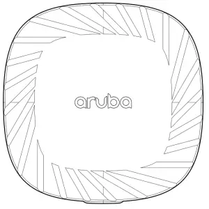
Figure 1 AP-505 Front View
Figure 2 AP-504 Front View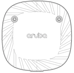
External Antenna Connectors
The AP-504 access points are equipped with two external antenna connectors located on the front corners of the access point (see Figure 2). Antenna ports A0 and A1(corresponding with radio chain 0 and 1), are used for both radios and bands (RF signals are diplexed).
External antennas for this device must be installed by an Aruba Certified Mobility Professional (ACMP) or another Aruba-certified technician, using manufacturer-approved antennas only. The Equivalent Isotropically Radiated Power (EIRP) levels for all external antenna devices must not exceed the regulatory limit set by the host country/domain. Installers are required to record the antenna gain for this device in the system management software. A list of approved antennas can be found at: http://www.arubanetworks.com/assets/og/OG_AP-500Series.pdf.
Figure 3 LEDs (AP-505 shown)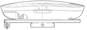
LEDs
System Status
The System Status LED indicates the operating condition of the access point.
Table 1 System Status LED ![]()
| Color/State | Meaning |
| Off | Device Powered off |
| Green- solid | Device ready, fully functional, no network restrictions |
| Green- blinking 1 | Device booting, not ready |
| Green- flashing off 2 | Device ready, fully functional, uplink negotiated in sub-optimal speed (<1Gbps) |
| Green- flashing on 3 | Device in deep-sleep mode |
| Amber- solid | Device ready, restricted power mode (IPM restrictions applied), no network restrictions |
| Amber- flashing off | Device ready, restricted power mode (IPM restrictions applied), uplink negotiated in sub-optimal speed (<1Gbps) |
| Red | System error condition – Immediate action required |
- Blinking: one second on, one second off, 2 seconds cycle.
- Flashing off: mostly on, fraction of a second off, 2 seconds cycle.
- Flashing on: mostly off, fraction of a second on, 2 seconds cycle.
Radio Status
The Radio Status LED indicates the operating mode of the access point’s radios.
Table 2 Radio Status LEDs ![]()
| Color/State | Meaning |
| Off | Device powered off, or both radios disabled |
| Green- solid | Both radios enabled in access mode |
| Green- blinking | One radio enabled in access mode, other disabled |
| Amber- solid | Both radios enabled in monitor mode |
| Color/State | Meaning |
| Amber- blinking | One radio enabled in monitor mode, other disabled |
| Green/Amber- alternating1 | Green: one radio in access mode Amber: one radio in monitor mode |
1. Alternating: one second each color, 2 seconds cycle.
LED Display Settings
The LEDs have three operating modes that can be selected in the system management software:
- Normal mode: Refer to Table 1and Table 2
- Off mode: LEDs are off
- Blink mode: LEDs blink green (synchronized)
Figure 4 AP-505 Rear View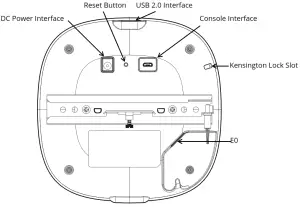
Cable Guide
The cable guide on the rear of the access point is used to organize cables, as shown in Figure 5. The use of the cable guide is optional and does not support all types of cables and plugs.
Figure 5 Cable Guide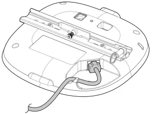
Bluetooth Low Energy and Zigbee Radio
500 Series access points are equipped with an integrated BLE and Zigbee radio that provide the following capabilities:
- location beacon applications
- wireless console access
- IOT gateway applications
Console Port
The console port is a Micro-B connector located on the back of this device. A proprietary serial adapter cable (APCBL-SERU) is needed to use this interface. It is sold separately to connect the AP to a serial terminal or a laptop for direct local management (a standard USB cable cannot be used for this interface).
Ethernet Port
The Aruba 500 Series is equipped with a 10/100/1000Base-T auto-sensing MDI/MDX Ethernet port (E0). This E0 port supports IEEE 802.3af and 802.3at Power over Ethernet compliance, accepting power from a Power Sourcing Equipment (PSE) such as a PoE midspan injector, or network infrastructure that support PoE.
Kensington Lock Slot
The 500 Series is equipped with a Kensington lock slot for additional physical security.
USB 2.0 Interface
The top of this access point is equipped with a USB-A port that is compatible with selected cellular modems and other peripherals. When active, this port can supply up to 5W/1A to a connected device.
Reset Button
The reset button located on the back of the device can be used to reset the access point to factory default settings or turn off/on the LED display.
There are two ways to reset the access point to factory default settings:
Reset the AP during normal operation press and hold down the reset button using a small, narrow object such as a paper clip for more than 10 seconds during normal operation.
Reset the AP while powering up
- Press and hold down the reset button using a small, narrow object such as a paper clip while the access point is not powered on (either via DC power or PoE).
- Connect the power supply (DC or PoE) to the access point while the reset button is being held down.
- Release the reset button on the access point after 15 seconds.
To turn off/on the LED display, press and release the reset button using a small, narrow object, such as a paperclip for less than 10 seconds during normal operation of the access point.
Power
E0 port supports PoE-in (AP is a PoE-PD device), allowing the device to draw power from compliant PoE power sources. If PoE is not available, a proprietary AP-AC-12V30B power adapter (sold separately) can be used to power the access point. When both PoE and DC power sources are available, the DC power source takes precedence. In that case, the access point simultaneously draws a minimal current from the PoE source. In the event that the DC source fails, the access point switches to the PoE sources.
The Intelligent Power Monitoring (IPM) feature may also be used to manage the power consumption preferences for this device. When enabled, the user may enable/disable power restrictions for the access point using Aruba’s AP management software.
Table 3 lists operational restrictions when the access point is powered by different power options.
Table 3 Power Options and Operational Restrictions
| Power Source | IPM | Restrictions |
| DC power | n/a | No restrictions, all capabilities available |
| PoE 802.3at | n/a | No restrictions, all capabilities available |
| PoE 802.3af | enabled | All capabilities available (features may be disabled per IPM configuration) |
| PoE 802.3af | disabled | USB disabled |
The 500 Series access points support a deep-sleep mode to deliver significant power and cost savings.
Before You Begin
Refer to the sections below before beginning the installation process.
 FCC Statement: Improper termination of access points installed in the United States configured to non-US model controllers will be in violation of the FCC grant of equipment authorization. Any such willful or intentional violation may result in a requirement by the FCC for immediate termination of operation and may be subject to forfeiture (47 CFR 1.80).
Pre-Installation Checklist
Before installing your Aruba 500 Series access point, be sure that you have the following (not included with the AP):
- A mount kit compatible with the AP and mount surface
- Cat5E or better UTP cable with network access
- One or more external antennas (when using the AP-504)
- (Optional) a compatible 12V AC-to-DC power adapter with power cord
- (Optional) a compatible PoE midspan injector with power cord
- (Optional) a compatible snap-on front cover (for easy aesthetic customization)
- (Optional) an AP-CBL-SERU console cable Also make sure that (at least) one of the following network services is supported:
- Aruba Discovery Protocol (ADP)
- DNS server with an “A” record
- DHCP Server with vendor-specific options
![]() The Aruba 500 Series access point is designed in compliance with governmental requirements so that only authorized network administrators can change the settings. For more information about access point configuration, refer to the AP Software Quick Start Guide.
The Aruba 500 Series access point is designed in compliance with governmental requirements so that only authorized network administrators can change the settings. For more information about access point configuration, refer to the AP Software Quick Start Guide.
Identifying Specific Installation Locations
Use the access point placement map generated by Aruba RF Plan software application to determine the proper installation location(s). Each location should be as close as possible to the center of the intended coverage area and should be free from obstructions or obvious sources of interference. These RF absorbers/reflectors/ interference sources will impact RF propagation and should be accounted for during the planning phase and adjusted for in RF plan.
![]() Use of this equipment adjacent to or stacked with other equipment should be avoided because it could result in improper operation. If such use is necessary, this equipment and the other equipment should be observed to verify that they are operating normally.
Use of this equipment adjacent to or stacked with other equipment should be avoided because it could result in improper operation. If such use is necessary, this equipment and the other equipment should be observed to verify that they are operating normally.
Identifying Known RF Absorbers/Reflectors/Interference Sources
Identifying known RF absorbers, reflectors, and interference sources while in the field during the installation phase is critical. Make sure that these sources are taken into consideration when you attach an access point to its fixed location.
RF absorbers include:
- Cement/concrete—Old concrete has high levels of water dissipation, which dries out the concrete, allowing for potential RF propagation. New concrete has high levels of water concentration in the concrete, blocking RF signals.
- Natural Items—Fish tanks, water fountains, ponds, and trees
- Brick
RF reflectors include: - Metal Objects—Metal pans between floors, rebar, fire doors, air conditioning/heating ducts, mesh windows, blinds, chain link fences (depending on aperture size), refrigerators, racks, shelves, and filing cabinets.
- Do not place an access point between two air conditioning/heating ducts. Make sure that access points are placed below ducts to avoid RF disturbances.
RF interference sources include: - Microwave ovens and other 2.4 or 5 GHz objects (such as cordless phones)
- Cordless headset such as those used in call centers or lunch rooms
![]() Portable RF communications equipment (including peripherals such as antenna cables and external antennas) should be used no closer than 30 cm (12 inches) to any part of the access point. Otherwise, degradation of the performance of this equipment could result.
Portable RF communications equipment (including peripherals such as antenna cables and external antennas) should be used no closer than 30 cm (12 inches) to any part of the access point. Otherwise, degradation of the performance of this equipment could result.
RF Radiation Exposure Statement: This equipment complies with FCC RF radiation exposure limits. This equipment should be installed and operated with a minimum distance of 13.78 inches (35cm) between the radiator and your body for 2.4 GHz and 5 GHz operations. This transmitter must not be co-located or operating in conjunction with any other antenna or transmitter.
Access Point Installation
the Aruba 500 Series access points are designed for ceiling or wall mounted deployments. Several optional mount kits are available to attach the Aruba 500 Series access point to a variety of surfaces. These mount kits are available as accessories and must be ordered separately. Refer to the online ordering guide at http://www.arubanetworks.com/assets/og/OG_AP-500Series.pdf
All Aruba access points should be professionally installed by an Aruba-Certified Mobility Professional (ACMP). The installer is responsible for ensuring that grounding is available and meets applicable national and electrical codes. Failure to properly install this product may result in physical injury and/or damage to property.
![]() The installer is responsible for securing the access point onto the ceiling tile rail. Failure to properly install this product may result in physical injury and/or damage to property.
The installer is responsible for securing the access point onto the ceiling tile rail. Failure to properly install this product may result in physical injury and/or damage to property.![]() Use of accessories, transducers and cables other than those specified or provided by the manufacturer of this equipment could result in increased electromagnetic emissions or decreased electromagnetic immunity of this equipment and result in improper operation.
Use of accessories, transducers and cables other than those specified or provided by the manufacturer of this equipment could result in increased electromagnetic emissions or decreased electromagnetic immunity of this equipment and result in improper operation.
Software
For instructions on choosing operating modes and initial software configuration, refer to the AP Software Quick Start Guide.
![]() Aruba access points are classified as radio transmission devices, and are subject to government regulations of the host country. The network administrator(s) is/are responsible for ensuring that configuration and operation of this equipment is in compliance with their country’s regulations. For a complete list of approved channels in your country, refer to the Aruba Downloadable Regulatory Table at support.arubanetworks.com.
Aruba access points are classified as radio transmission devices, and are subject to government regulations of the host country. The network administrator(s) is/are responsible for ensuring that configuration and operation of this equipment is in compliance with their country’s regulations. For a complete list of approved channels in your country, refer to the Aruba Downloadable Regulatory Table at support.arubanetworks.com.
Verifying Post-Installation Connectivity
The integrated LED on the access point can be used to verify that the access point access point is receiving power and initializing successfully (see Table 1-Table 2). Refer to the AP Software Quick Start Guide for further details on verifying post-installation network connectivity.
Electrical and Environmental Specifications
For additional specifications on this product, please refer to the product data-sheet at www.arubanetworks.com
Electrical
- Ethernet:
- E0 port: 10/100/1000BaseT auto-sensing MDI/MDX wired RJ45 network connectivity port
- Power:
- 12V DC power interface, support powering through AC-to-DC power adapter (AP-AC-12V30B)
- Power over Ethernet (PoE): 802.3af or 802.3at compliant source
![]() If a power adapter other than the Aruba-approved adapter is used in the US or Canada, it should be NRTL listed, with an output rated 12V DC, minimum 0.75A, marked “LPS” and “Class 2,” and suitable for plugging into a standard power receptacle in the US and Canada.
If a power adapter other than the Aruba-approved adapter is used in the US or Canada, it should be NRTL listed, with an output rated 12V DC, minimum 0.75A, marked “LPS” and “Class 2,” and suitable for plugging into a standard power receptacle in the US and Canada.
Environmental
- Operating:
- Temperature: 0°C to +50°C (+32°F to +122°F)
- Humidity: 5% to 93% non-condensing
- Storage and transport:
- Temperature: -40°C to +70°C (-40°F to +158°F)
- Humidity: 5% to 93% non-condensing
![]() The Aruba 500 Series access points are for indoor use only. The access point, AC adapter, and all connected cables are not designed for outdoor use.
The Aruba 500 Series access points are for indoor use only. The access point, AC adapter, and all connected cables are not designed for outdoor use.![]() This device is intended for stationary use in partly temperature-controlled weather-protected environments.
This device is intended for stationary use in partly temperature-controlled weather-protected environments.
Regulatory Model Name
The following regulatory model numbers (RMN) apply to the 500 Series:
- AP-504 RMN: APIN0504
- AP-505 RMN: APIN0505
Safety and Regulatory Compliance
RF Radiation Exposure Statement: This equipment complies with RF radiation exposure limits. This equipment should be installed and operated with a minimum distance of 13.78 inches (35cm) between the radiator and your body for 2.4 GHz and 5 GHz operations. This transmitter must not be co-located or operating in conjunction with any other antenna or transmitter.
Changes or modifications to this unit not expressly approved by the party responsible for compliance could void the user’s authority to operate this equipment.
Federal Communication Commission
This device complies with Part 15 of the FCC Rules. Operation is subject to the following two conditions: (1)this device may not cause harmful interference, and (2) this device must accept any interference received, including interference that may cause undesired operation.
This equipment has been tested and found to comply with the limits for a Class B digital device, pursuant to Part 15 of the FCC Rules. These limits are designed to provide reasonable protection against harmful interference in a residential installation. This equipment generates, uses and can radiate radio frequency energy and, if not installed and used in accordance with the manufacturer’s instructions, may cause harmful interference to radio communications. However, there is no guarantee that interference will not occur in a particular installation. If this equipment does cause harmful interference to radio or television reception, which can be determined by turning the equipment off and on, the user is encouraged to try to correct the interference by one or more of the following measures:
- Reorient or relocate the receiving antenna.
- Increase the separation between the equipment and receiver.
- Connect the equipment to an outlet on a circuit different from that to which the receiver is connected.
- Consult the dealer or an experienced radio or TV technician for help.
Industry Canada
This Class B digital apparatus meets all of the requirements of the Canadian Interference-Causing Equipment Regulations. In accordance with Industry Canada regulations, this radio transmitter and receiver may only be used with an antenna, the maximum type and gain of which must be approved by Industry Canada. To reduce potential radio interference, the type of antenna and its gain shall be chosen so that the equivalent isotropic radiated power (EIRP) does not exceed the values necessary for effective communication. This device complies with Industry Canada’s license-exempt RSS regulations. Operation of this device is subject to the following two conditions: (1) this device may not cause interference, and (2) this device must accept any interference, including interference that may cause undesired operation. When operated in the 5.15 to 5.25 GHz frequency range, this device is restricted to indoor use to reduce the potential for harmful interference with co-channel Mobile Satellite Systems.
Canadian Caution
This radio transmitter model APIN0504/APIN0505 has been approved by Industry Canada to operate with the antenna types listed in the table in the online ordering guide (link provided below) with the maximum permissible gain indicated. Antenna types not included in this list, having a gain greater than the maximum gain indicated for that type, are strictly prohibited for use with this device. http://www.arubanetworks.com/assets/og/OG_AP-500Series.pdf
 European Union Regulatory Conformance
The Declaration of Conformity made under Radio Equipment Directive 2014/53/EU is available for viewing at: www.hpe.com/eu/certificates. Select the document that corresponds to your device’s model number as it is indicated on the product label
This radio transmitter model has been approved to operate with the antenna types listed in the online ordering guide (link provided below) with the maximum permissible gain indicated. Antenna types not included in this list, having a greater gain than the maximum gain indicated for the type, are strictly prohibited for use with this device. Compliance is only assured if Aruba-approved accessories as listed in the ordering guide are used. http://www.arubanetworks.com/assets/og/OG_AP-500Series.pdf
Wireless Channel Restrictions 5150-5350MHz band is limited to indoors only in the following countries; Austria (AT), Belgium (BE), Bulgaria (BG), Croatia (HR), Cyprus (CY), Czech Republic (CZ), Denmark (DK), Estonia (EE), Finland (FI), France (FR), Germany (DE), Greece (GR), Hungary (HU), Iceland (IS), Ireland (IE), Italy (IT), Latvia (LV), Liechtenstein (LI), Lithuania (LT), Luxembourg (LU), Malta (MT), Netherlands (NL), Norway (NO), Poland (PL), Portugal (PT), Romania (RO), Slovakia (SK), Slovenia (SL), Spain (ES), Sweden (SE), Switzerland (CH), Turkey (TR), United Kingdom (UK).
| Radio | Frequency Range MHz | Max EIRP |
| BLE/Zigbee | 2402-2480 | 9 dBm |
| Wi-Fi | 2412-2472 | 20 dBm |
| 5150-5250 | 23 dBm | |
| 5250-5350 | 23 dBm | |
| 5470-5725 | 30 dBm | |
| 5725-5850 | 14 dBm |
![]() Lower power radio LAN product operating in 2.4 GHz and 5 GHz bands. Please refer to the ArubaOS User Guide/Instant User Guide for details on restrictions.
Lower power radio LAN product operating in 2.4 GHz and 5 GHz bands. Please refer to the ArubaOS User Guide/Instant User Guide for details on restrictions.
Medical
- Equipment not suitable for use in the presence of flammable mixtures.
- Connect to only IEC 60950-1 or IEC 60601-1 certified products and power sources. The end user is responsible for the resulting medical system complies with the requirements of IEC 60601-1.
- Wipe with a dry cloth, no additional maintenance required.
- No serviceable parts, the unit must be sent back to the manufacturer for repair.
- No modifications are allowed without Aruba approval.
![]() This device is intended for indoor use in professional healthcare facilities.
This device is intended for indoor use in professional healthcare facilities.![]() This device has no IEC/EN60601-1-2 essential performance.
This device has no IEC/EN60601-1-2 essential performance.
![]() Use of this equipment adjacent to or stacked with other equipment should be avoided because it could result in improper operation. If such use is necessary, this equipment and the other equipment should be observed to verify that they are operating normally.
Use of this equipment adjacent to or stacked with other equipment should be avoided because it could result in improper operation. If such use is necessary, this equipment and the other equipment should be observed to verify that they are operating normally.
![]() Compliance is based on the use of Aruba approved accessories. Refer to the ordering guide for this access point at
Compliance is based on the use of Aruba approved accessories. Refer to the ordering guide for this access point at
http://www.arubanetworks.com/assets/og/OG_AP-500Series.pdf.
![]() Use of accessories, transducers and cables other than those specified or provided by the manufacturer of this equipment could result in increased electromagnetic emissions or decreased electromagnetic immunity of this equipment and result in improper operation.
Use of accessories, transducers and cables other than those specified or provided by the manufacturer of this equipment could result in increased electromagnetic emissions or decreased electromagnetic immunity of this equipment and result in improper operation.
![]() Portable RF communications equipment (including peripherals such as antenna cables and external antennas) should be used no closer than 30 cm (12 inches) to any part of the access point. Otherwise, degradation of the performance of this equipment could result.
Portable RF communications equipment (including peripherals such as antenna cables and external antennas) should be used no closer than 30 cm (12 inches) to any part of the access point. Otherwise, degradation of the performance of this equipment could result.
Contact Aruba
| Main Site | https://www.arubanetworks.com |
| Support Site | https://support.arubanetworks.com |
| Airheads Social Forums and Knowledge Base | https://community.arubanetworks.com/ |
| North America Telephone | 1-800-943-4526 1-408-754-1200 |
| International Telephone | https://www.arubanetworks.com/support-services/contact-support/ |
| Software Licensing Site | https://www.hpe.com/networking/support |
| End-of-Life Information | https://www.arubanetworks.com/support-services/end-of-life/ |
| Security Incident Response Team (SIRT) | https://www.arubanetworks.com/support-service/security-bulletins/ Email: [email protected] |
Copyright
© Copyright 2019 Hewlett Packard Enterprise Development LP
Open Source Code
This product includes code licensed under the GNU General PublicLicense, the GNU Lesser General Public License, and/or certain other open source licenses.
A complete machine-readable copy of the source code corresponding to such code is available upon request. This offer is valid to anyone in receipt of this information and shall expire three years following the date of the final distribution of this product version by Hewlett Packard Enterprise Company.
To obtain such source code, send a check or money order in the amount of US $10.00 to:
Hewlett Packard Enterprise Company
Attn: General Counsel
6280 America Center Drive
San Jose, CA 94089
USA
Warranty
This hardware product is protected by an Aruba warranty. For more details, visit www.hpe.com/us/en/support.html
![]()
![]()


FAQS
Are these us or rw?
Complete scammers! They don’t work in the US
Does it come with the license ?
No. If you are seeing up a virtual controller them no license is needed. If you are going with the hardware controller then you will need to license appropriately.
Is this the R2H29A model?
Yes SIR
Is this (US)?
Yes, US unified
How do I find my Aruba access point model?
To view the Access Point Details page, follow these steps: Tap the Inventory( ) tile on the Aruba Instant On home page or tap the Site Health( ) banner and then tap Show inventory. Tap any of the APs listed in the Inventory list. The Access Point Details page is displayed with details.
What is the difference between the AP-504 and the AP-505?
The AP-504 and the AP-505 are identical except that the AP-505 also supports 802.11ax.
Are there any other differences between the AP-504 and the AP-505?
Yes, they have different default SSIDs. The default SSID for the AP-504 is “arubanetworks” and the default SSID for the AP-505 is “arubanetworks_ax”.
What are some of the differences between 802.11ax and 802.11ac?
802.11ax provides a number of improvements over 802.11ac, including higher throughput, lower latency, and higher density support in a single radio. For more information about these improvements, see Appendix A, “802.11ax Features.”
Can I use an AP-504 or an AP-505 in my network today?
Yes, you can use either an AP-504 or an AP-505 in your network today as long as you have a controller that supports 802.11ax (such as ArubaOS 6.4 or later). If you do not have a controller that supports 802.11ax, you will need to upgrade to one before you can use an AP-505 in your network. For more information about upgrading your controller to support 802.11ax, see Appendix B, “Upgrading Your Controller.”
Can I use an AP-504 or an AP-505 in my network if I do not have a controller?
Yes, you can use either an AP-504 or an AP-505 in your network if you do not have a controller by using Aruba Instant (controllerless) mode with Aruba Instant Cloud Services . For more information about Aruba Instant mode and Aruba Instant Cloud Services, see Appendix C, “Aruba Instant Overview.”
What are some of the differences between Aruba Instant mode and controllerless mode?
There are several differences between Aruba Instant mode and controllerless mode including how they handle security policies (Aruba Instant handles security policies at Layer 2 while controllerless mode handles security policies at Layer 3), how they handle authentication (Aruba Instant uses MAC address authentication while controllerless mode uses username/password authentication), how they handle mobility (Aruba Instant uses Layer 2 mobility while controllerless mode uses Layer 3 mobility), and how they handle roaming (Aruba Instant uses Layer 2 roaming while controllerless mode uses Layer 3 roaming). For more information about these differences, see Appendix C, “Aruba Instant Overview.”
Access point Aruba is very reliable, efficient and stable. In the organization, we use the IAP version, which does not require a physical controller. All access points are managed from the central AirWave server, which also monitors devices and wifi networks.
The default IP address of the managed device is 172.16. 0.254/24. Connect a PC or workstation to any line port on the managed device, then enter this IP address into a supported Web browser to launch the Setup Wizard.
With Wi-Fi Aruba you can get high-speed wireless internet access on your laptop, tablet or smartphone at several hotspots on the island, including restaurants, resorts, bars and even on the beach. You can access the Wi-Fi Aruba service using a Wi-Fi prepaid card or your Credit Card.
Aruba Instant On access points replace a typical router. Just plug an Aruba Instant On access point into the cable that brings the internet into your home to enable your Wi-Fi network.


