Spellman MCP4 High Voltage DC to DC Converter Power Supply User Guide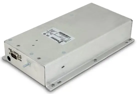
SAFETY INFORMATION
DANGER
HIGH VOLTAGE
RISK OF ELECTROCUTION
Observe extreme caution when working with this equipment
- High voltage power supplies must always be connected to protective earth
- Do not touch connections unless equipment is turned off and the capacitance of both the load and power supply are grounded
- Allow adequate time for discharge of internal capacitance of the power supply
- Do not ground yourself or work under wet or damp conditions
Servicing Safety
- Maintenance may require removing the Instrument cover with the power on
- Servicing should only be done by qualified personnel aware of the hazards
- Return to supplier for servicing
Unit Description
The MCP4 is a high voltage detector PSU for mass spectrometers and other scientific instruments.
The output is isolated from ground to 15kV, such that it can be floated upon the HV output of an accelerator voltage or other high voltage source, as shown in the diagram below.
The unit has been designed to provide low noise and ripple, with particular design features to minimise crosstalk with the HV source upon which it is floated.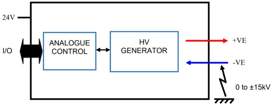
The units are provided with fixed HV input and output cables, specified in Section 3.4
HV Unit Ratings
The ratings are as follows:
HV Output: 0 to 4kVdc, 600µA (+VE with respect to -VE)
Input: 24Vdc +/-5%, 700mA (there is no operator changeable fuse)
Operating Temperature: 0°C to 50°C
Relative humidity rating: 5% to 90% (non-condensing)
Altitude: Up to 3000m above mean sea level
Mass: 1.75 Kg
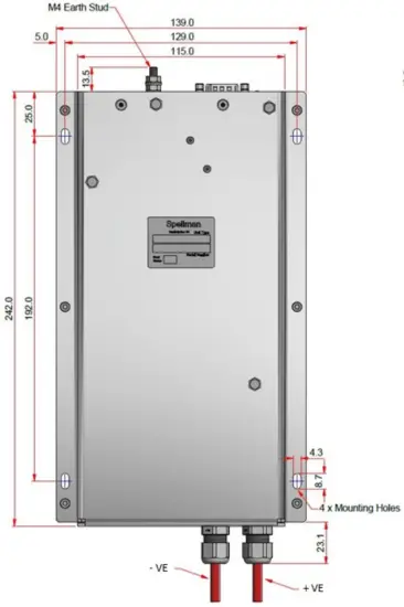
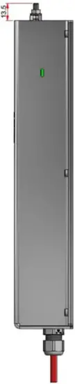
Dimensions: 242 x 139 x 46 mm (see layout in Appendix 1)
Safety
The unit’s HV output is at a non-hazardous level to the requirements of EN61010-1. The conditions of this manual must be complied with to maintain safety. Operating the unit in a manner not specified in this manual may impair the protection against electric shock that the unit may normally provide.
Note: Although the HV generated by this unit itself is non-hazardous, it may become hazardous when connected to an external supply, depending upon the rating of the external supply.
The unit has been evaluated for use in a Pollution Degree 2, Installation Category II, environment.
Consideration should be given to conducting the following tests with the unit installed in the end product:
- Dielectric Voltage Withstand Test, between live parts of the unit and the end product chassis.
- Permissible Limits Tests with the unit installed in the end product.
- Temperatures on power electronic components, transformer windings and accessible surfaces.
Meaning of Symbols
SYMBOL | MEANING IN ENGLISH |
 | Refer to manual before operating |
| Caution, possibility of electric shock |
 | Caution, hot surface |
Regulatory Approval
The unit is designed to meet the requirements of EN 61010-1, UL 61010-1 and CAN/CSA-22.2 No. 61010-1. Please consult the factory for further approval information.
Installation of the HV Unit
Initial Inspection
Inspect the package exterior for evidence of damage due to handling in transit. Notify the carrier and
Spellman immediately if damage is evident. Do not destroy or remove any of the packing material used in a damaged shipment.
After unpacking, inspect the panel and chassis for visible damage.
Note: Failure to comply with the above could compromise the safe operation of the unit and invalidate the warranty.
Mechanical Installation
The unit should only be used in a Pollution Degree 2 Installation Category II environment.
The unit is intended for use as a component and no surface of the unit should be accessible in the end product.
The Mechanical outline is shown in Appendix 1.
Electrical Installation
The units must be terminated safely befor6e operation. The case of the unit must be connected to the PE earth of the final system using the stud provided on the case.
The dc power input shall be provided by a SELV or Double insulated, UL recognised, DC power supply unit.
HV Unit Interfaces
Control and Input power Connection
The unit is connected via an industry standard 9 Way D-Type Connector:
| PIN | CONNECTION |
| 1 | VPROG |
| 2 | VPRG_RTN |
| 3 | ENABLE |
| 4 | ENABLE_RTN |
| 5 | Power GND |
| 6 | Signal GND |
| 7 | VMON |
| 8 | Not used |
| 9 | +24Vdc |
HV Output Connection
| CONNECTION | CONNECTOR TYPE | CABLE LENGTH |
| HV CABLE x 2 (+VE and -VE) | HRG58-20-2 HV COAX CABLE 20KV BRAIDED RED 4.95mm DIA | 1150 ± 10mm |
The cable braid is connected to chassis ground. It is recommended to use the braid as a HV return for a connected high voltage reference supply.
Operation of the HV Unit
Control and Monitor Signals
The following signals are used to control and monitor the HV unit:
| Control, Monitor signal | Attribution | Pin | Type | Level |
| Voltage program control | VPROG | 1 | Vdc | 0-10V corresponding to 0- 4kV Full Scale |
| Enable control | ENABLE | 3 | TTL | Hi = Enable (>2V). Imax=19mA or Vmax=11V |
| Voltage output monitor | VMON | 7 | Vdc | 0-10V corresponding to full scale HV output |
LED Indicator
| Parameter | Type | Description |
| HV Enabled | LED | ON= +5V typically |
Appendix 1 – Mechanical Outline