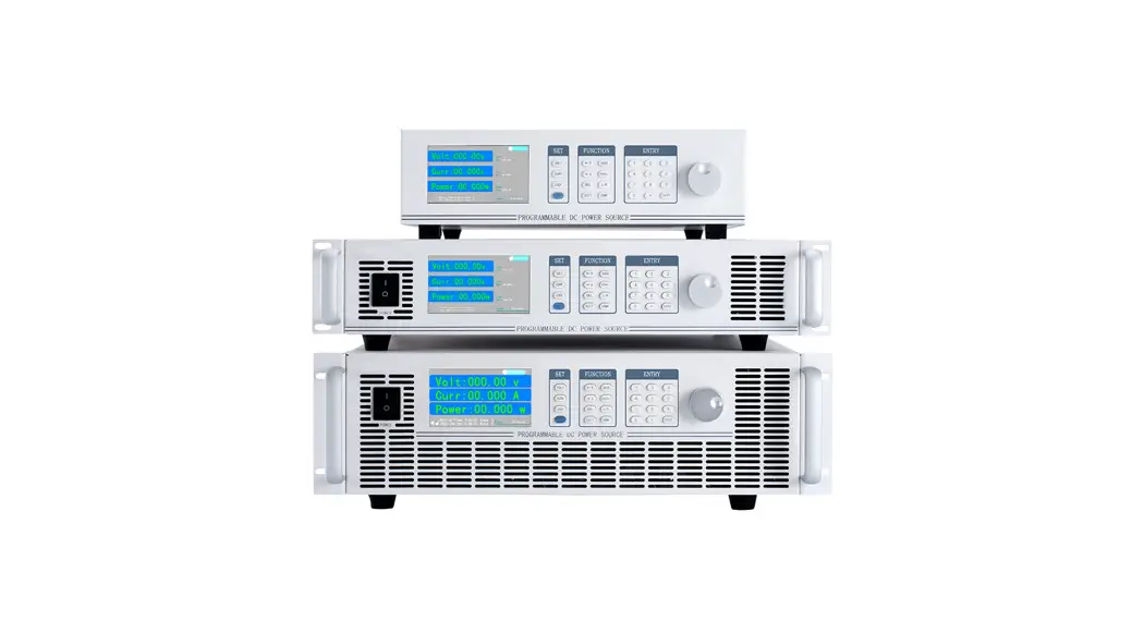
![]() OWP-H Series High Power DC Supply
OWP-H Series High Power DC Supply
User Guide
OWP-H Series High Power DC Supply
For product support, visit: www.owon.com.hk/download
Mar. 2022 edition V1.0.0
Copyright © LILLIPUT Company. All rights reserved.
LILLIPUT’s products are under the protection of the patent rights, including ones that have already obtained the patent rights and those which are applying for. The information in this manual will replace all that in the materials published originally.
The information in this manual was correct at the time of printing. However, LILLIPUT will continue to improve products and reserves the right to change specifications at any time without notice.![]() is the registered trademark of the LILLIPUT Company.
is the registered trademark of the LILLIPUT Company.
Fujian LILLIPUT Optoelectronics Technology Co., Ltd.
No. 19, Heming Road
Lantian Industrial Zone, Zhangzhou 363005 P.R. China
| Tel: +86-596-2130430 Web: www.owon.com | Fax: +86-596-2109272 E-mail: [email protected] |
General Warranty
We warrant that the product will be free from defects in materials and workmanship for a period of 2 years (1 year for accessories) from the date of purchase of the product by the original purchaser from our company. This warranty only applies to the original purchaser and is not transferable to a third party.
If the product proves defective during the warranty period, we will either repair the defective product without charge for parts and labor or will provide a replacement in exchange for the defective product. Parts, modules, and replacement products used by our company for warranty work may be new or reconditioned like new. All replaced parts, modules, and products become the property of our company.
In order to obtain service under this warranty, the customer must notify our company of the defect before the expiration of the warranty period. The customer shall be responsible for packaging and shipping the defective product to the designated service center, a copy of the customer’s proof of purchase is also required.
This warranty shall not apply to any defect, failure, or damage caused by improper use or improper or inadequate maintenance and care. We shall not be obligated to furnish service under this warranty a) to repair damage resulting from attempts by personnel other than our company representatives to install, repair or service the product; b) to repair damage resulting from improper use or connection to incompatible equipment; c) to repair any damage or malfunction caused by the use of not our supplies; or d) to service a product that has been modified or integrated with other products when the effect of such modification or integration increases the time or difficulty of servicing the product.
Please contact the nearest Sales and Service Offices for services.
Excepting the after-sales services provided in this summary or the applicable warranty statements, we will not offer any guarantee for maintenance definitely declared or hinted at, including but not limited to the implied guarantee for marketability and special-purpose acceptability. We should not take any responsibility for any indirect, special or consequent damages.
Back Panel
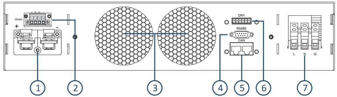
- DC output terminal: RED “+”, BLACK “-“
- Remote voltage compensation
- Duct outlet (No obstructions within 10 cm)
- RS485 interface(Female)
- CAN interface
- Dry contact/Analog interface
- AC Input
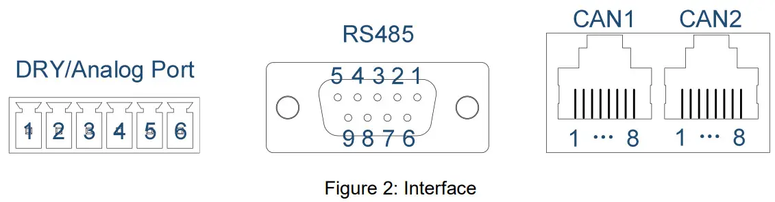
Interface
Interface | PIN | Function |
| Digital IO | 1 | Normally open contact (Output of the dry contact) |
| 2 | Common contact (Output of the dry contact) | |
| 3 | Normally closed contact (Output of the dry contact) | |
| 4 | NC | |
| 5 | The input of the dry contact | |
| 6 | ||
| RS485 | 1 | 485-A |
| 2 | 485-B | |
| 3~9 | NC |
- Digital IO interface: PIN 1 to 3 is a dry contact output interface with complementary functions of normally open and normally closed. PIN2 is the common end of dry contact. Dry contact output capacity: 1A/30VDC or 0.15A/220VAC; PIN 5 to 6 are dry contact input interfaces, which can be set for external control of the output, external fault feedback, or external control of the buzzer;
- Analog interface: Analog interface is optional, and interface signals can be customized, two analog interface definitions as shown in the table above
- RS485 interface: Serial communication interface(Female), software using standard Modbus-RTU protocol;
- CAN interface: CAN1 and CAN2 are two internal parallel CAN bus interfaces, which facilitate the serial or parallel connections between devices. CAN communication also be used for communication between external devices;
Note: Analog interface is an optional interface (customizable), up to a maximum of four analogs, two analog input, and two analog output. Select 1-2 analog, interface see figure above; select 3-4 analog, the interface is RJ45-CAN1, 1-8 pin is defined as the positive and negative of analog input 1, the positive and negative of analog input 2, the positive and negative of analog output 1, the positive and negative of analog output 2. If you need an analog function, please inform us of the specific requirements in advance。
Voltage compensation
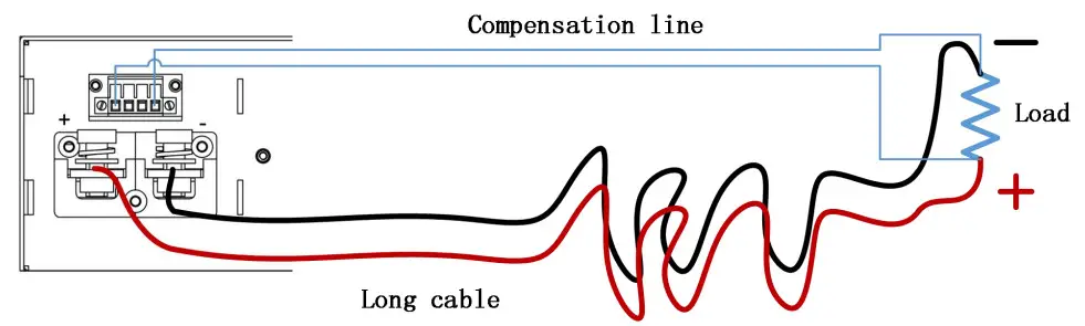 Figure 3: Schematic diagram of voltage compensation wiring
To use the remote voltage compensation function, use twisted-pair cables with high insulation. Positive and negative cables can not be connected inversely, as shown in the figure above. When not in use, the compensation terminals (SENSE) PIN1 and PIN2, PIN3, and PIN4 need to be shorted with short cables.
Parallel connection
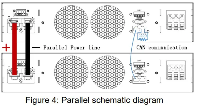
The device identifies and controls the parallel output through CAN communication. The diagram above shows the parallel connection.
Note:120 ohm is the CAN bus terminal resistor.
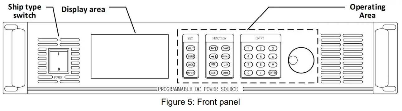
Front panel
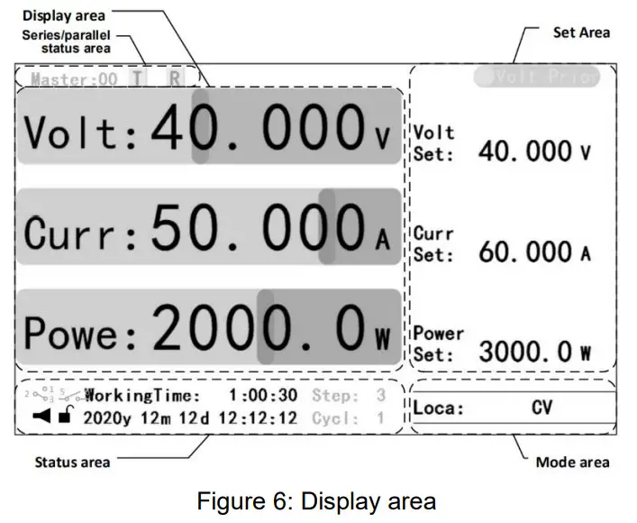
Display area
The Home displays real-time operating status information of the device, including:
- Display area: Current real-time output information;
- Setting area: setting of voltage, current, and power reference values, And voltage/current priority Settings;
- Status area: buzzer, lock key state, date and time information, working time, and dry contact and application mode state (gray);
- Mode area: Control mode and output mode;
- Series/parallel status area: when multiple machines are used in series/parallel, each device will display the master/slave machine number and CAN data receiving and receiving the status of the machine (gray);
Note:
- Display elements of the status area can be hidden. When an application mode is enabled, the status of the application mode will be displayed, and when the dry contact is used, the corresponding status icon will be displayed.
- Output mode is divided into common mode and application mode. 1. Common mode: CV(Constant voltage), CV(Constant current), CP(Constant power), or CV/CC/CP (Output is not open); 2. Application mode: such as CV Steps(Constant voltage steps), CC Steps(Constant current steps), and Hybrid steps in step mode.
Home
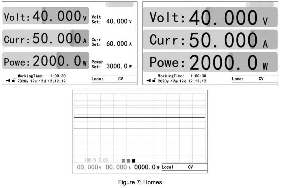
Three Homes, including:
- Home: displays the most comprehensive real-time working status information,
detailed in the section of “Display Area”; - Auxiliary Home: maximizes the real-time output information;
- Waveform Home: displays output real-time information in an intuitive waveform
manner.
Note
- The Home is the only interface for setting voltage, current, and power reference values.
- Press “ENTER” to set the sampling rate of the waveform displayed on the waveform Home. Whether the voltage, current, and power waveform are displayed can be controlled by pressing the “VOLT”, “CURR” or “POWER” key.
Operating area
Key | Description |
| VOLT | Voltage reference set |
| CURR | Current reference set |
| VOLT Double Click | Voltage priority switching |
| CURR Double Click | Current priority switching |
| VOLT+CURR | Power reference set |
| LOCK | Lock/Unlock |
| ON/OFF | Output ON/OFF |
| ←↑ | Left/Upshift |
| →↓ | Right/Downshift |
| DEL | Delete |
| EXIT | Returns the previous level or exit setting |
| SAVE | Save current settings |
| RECALL | Recall the saved settings |
| L/R | local/remote control mode |
| CONF | Function Menu |
| Key | Description |
| 0-9 | Number set |
| . | DOT |
| ENTER | To Menu/ Confirm input Switch between Home and Auxiliary Home |
| Knob | Description |
| Press | Menu Confirm Input Home: 1, Press once, Voltage set 2, Press twice, Current set 3, Press 3 times, Power set |
| Clockwise rotation | Increase value Upshift |
| Anti-Clock rotation | Reduce value Downshift |
Table 2: Key description
The operation area includes the setting area, function area, digital area, and knob. See “Appendix 1” in 《OWP_H Series Use Manual》 for key details.
Basic operation
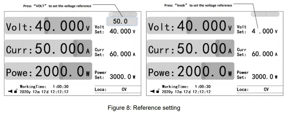
- Voltage reference setting: Press the “VOLT” key or press the “Knob” key to edit the voltage reference value, enter a valid value, and press the “ENTER” or “knob” key to confirm;
- Current reference setting: Press the “CURR” key or press the “Knob” key twice to edit the current reference value, enter a valid value, and press the “ENTER” or “knob” key to confirm;
- Power reference setting: Press the “VOLT” and “CURR” key simultaneously or press the “Knob” key three times to edit the power reference value, enter a valid value, and press the “ENTER” or “knob” key to confirm;
- Open and close output: Press the “ON/OFF” key to open the output (The “ON/OFF” key is light), and press the “ON/OFF” key to close the output (The “ON/OFF” key is OFF);
- Voltage/current priority switching: Close the output and double-click the “VOLT” or “CURR” key to switch the priority under the Home/auxiliary Home (Switch time is 1 second).
- SAVE Setting: 1. Under the Home, function setting UI or protection setting UI, if the Settings are valid, press the “SAVE” key to save the common mode data; On the application mode setting UI, if the Settings are valid, press “SAVE” key to save the application mode data;
- Recall setting: 1. On the Home/auxiliary Home, press the “RECALL” key to bring up the recall function option. Press “←↑the ” Or “→↓” key to select the data type and press the “ENTER” key to go to the recall UI for the data type. Press the”←↑” or “→↓” key to select the pre-called data and press the “ENTER” key to confirm the callback data. 2. On the application mode setting UI, press the “RECALL” key to bring up the relevant recall UI, press the”←↑” or “→↓” key to select the pre-called data, and press the “ENTER” key to confirm the callback data;
- Local/Remote mode switching: Press “L/R” to switch the local/remote mode temporarily in the Home/auxiliary Home (for the temporary test, the model is not saved); Buzzer control: Under the system setting UI, press “←↑” or “→↓” key to select Buzzer, and press “ENTER” key to enter buzzer control option. Select the corresponding level, and press the “ENTER” key to confirm;
Note:
- Common mode data includes voltage, current, and power reference values as well as parameters of function settings and protection settings in user Settings.
- When the key triggers the setting of the reference value, the preset area will be displayed above the corresponding operated element in the setting area. Enter a preset value through the number or knob key; When the knob triggers the setting of the reference value, the corresponding bit of the element to be operated in the setting area will flash. Through ” ← ↑ the ” Or ” → ↓ ” key to select the operation position, and then enter the preset value through the number or knob key.
- For local/remote mode Settings, see “LCD Menu – > User Settings – > Function setting ” section in 《OWP_H Series Use Manual 》 for details.
Appendix
Accessory
Certificate×1
Quick guide×1
1.5m input power line×1
6PIN terminal block×1
Key description
Area | Abbreviation | Description |
| Setting | VOLT | Voltage reference setting |
| CURR | Current reference setting | |
| VOLT+CURR | Power reference setting | |
| LOCK | Lock/unlock key | |
| ON/OFF | Open/close output | |
| Function | ←↑ | Move the cursor one bit to the left (numeric Settings) Move up one line |
| →↓ | Move the cursor one bit to the right (numeric Settings) Move down one line | |
| DEL | Deletes the value of the current bit | |
| EXIT | Return to the previous level or exit the setting | |
| SAVE | Save the normal data (In normal mode) Save App data (In data mode) | |
| RECALL | Recall saved data on Home | |
| L/R | Switch local/remote mode | |
| CONF | Enter the function UI | |
| Figure | 0~9 | Enter figure |
| . | Enter decimal point “.” | |
| ENTER | Enter the menu Input confirm Switch the home and the Auxiliary home | |
| Knob | Clockwise | Increment the input value (numeric Settings) Move Up N line |
| Anticlockwise | Decrease the input value (numeric Settings) Move Down the N line | |
| Press | Enter the menu Input confirm Under the home: 1. Press to set voltage reference 2. Press twice to set the current reference 3. Press three times to set the power reference 4. In the reference setting state, press confirm |
User setting list
| Scope | Name | Description | Default |
| Communication | Baud Rate | Baud rate setting | 9600 bps |
| CRC Alignment | Sending mode of CRC 16-bit check data | Little Endian | |
| Modbus Address | Modbus protocol address | Ox01 | |
| Function | Startup Mode | The device is in local/remote control mode after powering on | Local |
| Rise Time Of Voltage | Rise Time Of Voltage Setting | 30 mS | |
| Fall Time Of Voltage | Fall Time Of Voltage Setting | 0 mS | |
| Rise Time Of Current | Rise Time Of Current Setting | 30 mS | |
| Fall Time Of Current | Fall Time Of Current Setting | 0 mS | |
| Auto-Reco(Fault) | After the fault occurs, disable the output and check whether the output will be automatically restored after the specified time | 30 S, Close | |
| Auto-output(Hold) | After power-on, whether to automatically start output after the specified time | 30 S, Close | |
| Timing output | Reference time: Use the clock or power-on time as the reference time Time range Enable: Enables or disables this time range On/Off time: set the time range | Disable | |
| ParalleUSeries Connection | Type of connection: independent, parallel or series Master/slave: the master or slave | Independent | |
| Dry Contact output | Control mode: Disable, local or remote control Relationship: logic related to a fault, the startup, condition setting, or time setting Signal delay: delay from the dry contact action after the logic is triggered | Disable | |
| Dry Contact Input | Relationship: Disabled; Fault; Start or buzzer | Disable | |
| Protection | Over-Volt Value | Over-Voltage Protection Value | 105% VRated |
| Time of Duration | Trigger over-voltage protection time | 1000 mS | |
| Over-Curr Value | Over-Current Protection Value | 105% IRated | |
| Time of Duration | Trigger over-current protection time | 500 mS | |
| Levell Overload Value | Levell overload protection value | 105% PRated | |
| Time of Duration | Trigger Levell overload protection time | 10000 mS | |
| Level2 Overload Value | Level2 overload protection value | 110% PRated | |
| Time of Duration | Trigger Level2 overload protection time | 5000 mS | |
| Level3 Overload Value | Level3 overload protection value | 120% PRated | |
| Time of Duration | Trigger Level3 overload protection time | 1000 mS | |
| Under-Volt Protection | Under-voltage protection switch | Disable | |
| Protection Value | Under-voltage protection value | 10% VRated | |
| Protection Delay | Under-voltage protection detection delay | 1000 mS | |
| Time Of Duration | Trigger under-voltage protection time | 1500 mS | |
| Under-Curr Protection | Under-current protection switch | Disable | |
| Protection Value | Under- current protection value | 10% I Rated | |
| Protection Delay | Under- current protection detection delay | 1000 mS | |
| Time Of Duration | Trigger under current protection time | 1500 mS | |
| Short-Circuit Protection | Short-circuit protection switch | Disable | |
| Protection Value | Short-circuit protection voltage value | 5% varied | |
| Protection Delay | Short-circuit protection detection delay | 10 mS | |
| Time Of Duration | Trigger Short-circuit protection time | 20 mS | |
| Protection Switches | Relevant protection switches | — | |
| Password | Password | User Default Settings | — |
| Reset | Factory Reset | Restoring Factory Settings (except for information records) | — |
| Error Log reset | Clears fault Records | — | |
| System Data Reset | Clears UI or all system setting | ||
| User Data Reset | Clears selected data |
Warning list
| Name | Attribute | Description | Troubleshooting |
| Write EEPROM Err | Unrecoverable error | Write EEPROM Error | Power off, Restart. |
| Read EEPROM Err | Read EEPROM Error | Power off, Restart. | |
| Write FLASH Err | Write FLASH Error | Power off, Restart. | |
| Read FLASH Err | Read FLASH Error | Power off, Restart. | |
| Dill Speci Err | Different from Master specifications | Power off, Restart. | |
| External Error | Recoverable error | A fault was detected through dry contact input | Check whether dry contact signal input is normal and exclude alarm signal. |
| Driver Protect | Driver circuit error | Power off, Restart. | |
| HW Over-Volt P | The hardware over-voltage circuit detects an over-voltage error | Confirm start overshoot or steady overshoot (overshoot in working process), if it is start overshoot, can set “priority” to “current priority”, can also set “Rise Time Of Volt” parameter to a reasonable value(voltage priority); If it is a steady state overshoot and the voltage is not more than 1.3 times the rated voltage, you can tum off the hardware overvoltage protection function. If the voltage is more than 1.3 times the rated voltage, install an anti-reverse diode on the output side. | |
| HW Over-Curr P | The hardware over-current circuit detects an over-current Error | Confirm start overshoot or steady overshoot (overshoot in working process), if it is start overshoot, can set “priority” to “voltage priority”, can also set “Rise Time Of Volt” parameter to a reasonable value(voltage priority); If steady-state overshoot occurs, disable hardware overcurrent Protection. | |
| Over-Volt P | The software detects an over-voltage error | Confirm start overshoot or steady overshoot (overshoot in working process), if it is start overshoot, can set priority to “voltage priority”, can also set “Rise Time” parameter to a reasonable value; If the overshoot is steady state, the “over-current protection value” or “overcurrent duration” can be appropriately increased; | |
| Over-Cu rr P | The software detects an over-current error | Confirm start overshoot or steady overshoot (overshoot in working process), if it is start overshoot, can set “priority” to “voltage priority”, can also set “Rise Time Of Curr” parameter to a reasonable value(current priority); In the case of steady overshoot, the “overcurrent protection value” or “overcurrent duration” can be appropriately raised. | |
| Under-Volt P | The software detects an under-voltage error | Check whether the error is reasonable. If not, reset under-voltage protection parameters. | |
| Under-Curr P | The software detects an under-current error | Check whether the error is reasonable. If not, reset under-current protection parameters. | |
| Short-Circuit P | The software detects an short-circuit error | Check whether the short-circuit protection occurs. If the short-circuit error occurs, rectify the short-circuit error. Otherwise, reset the short-circuit protection parameters. | |
| Over-Load P | The software detects an overload error | Eliminate overload error or adjust overload protection parameters. | |
| Over Temperature | The software detects an over- Temperature error | Check whether the power supply air duct is blocked. | |
| Error Resume | Automatic error recovery is enabled, recoverable errors are detected, and recovery attempts fail 10 times | After confirming the cause of the error and troubleshooting, restart the machine. The error alarm can be cleared by pressing the “EXIT” key on the main UI. | |
| key is locked | Warming | Key locked | Press the “LOCK” key to unlock it. |
| Return to HOME | Operation method in the home | Return to the main UI and operate. | |
| Close Output | Method of operation in the closed output state | Operation after closing output | |
| RemoteCntr:Com ms | Operate keys in remote mode | Press “UR” to switch back to local control. | |
| RemoteCntrAnalo g | |||
| Switching Prior | Cannot start output during priority switching | Open output later. | |
| Please Later! | The priority cannot be switched again during priority switching | Wait 1 second and switch the priority again. | |
| Step Mode Is En | Cannot enable other the mode in step mode | Operation after Turn off Step mode. | |
| Chg Mode Is En | Cannot enable other the mode in charge mode | Turn off charging mode before operation. | |
| Func Mode Is En | Cannot Enable other mode In function generator mode | Tum off function generator before operation. | |
| Exit Setting | Illegal operation | Operation after exiting the Settings. | |
| Invalid Operate | The save and call functions are unavailable in the current UI | Perform operations on the correct UI. | |
| Value Exceeds | The input value exceeds the legal range | Input valid value. | |
| Value Too Small | |||
| Not Be Set To ‘0’ | The input value cannot be ‘0’ | Input valid value. | |
| Passward Error | Incorrect password input | Input the correct password, if you forget the password, call our company. | |
| Unset Volt Ref | The output cannot be open without setting the voltage reference | Set the voltage reference and start the output. | |
| Unset Curr Ref | The output cannot be open without setting the current reference | Set the current reference and start the output. | |
| Unset Power Ref | The output cannot be open without setting the power reference | Set the power reference and start the output. | |
| Illegal Data | Saving a data group is invalid | Save the data group after setting it correctly. | |
| Full Data Space | 128 data groups are full | Delete redundant data groups and save them. | |
| No Dada | The recall data group is empty | Call data after saving the corresponding data group. | |
| AddrRange :1-247 | Invalid MODBUS address | Input valid address | |
| Func Code Err | Communication error | Invalid function code | Operate according to the communication protocol; |
| RegisterAddrErr | Invalid register address | Operate according to the communication protocol; | |
| Data Range Err | Illegal data | Operate according to the communication protocol; | |
| Local Mode Err | The device is in local control mode | Switch to remote mode |


