
SR128 User Manual
![]()
| SR128 User Manual | Rev. A |
Document History
Date | Version | Author | Change |
11 Sep 2022 | A | Huy Le | Initial release |
General Note
This document is intended for information purposes.
STYL makes every effort to ensure that the quality of the information is available. The content of this documentation is provided on an “as is” basis and may contain deficiencies or inadequacies.
STYL disclaims any warranty and all responsibility for the application of the device(s) that is made in relation to the accuracy, reliability or contents of this document. STYL is not liable for any injury, loss or damage of any kind incurred for the use of or reliance upon information.
STYL reserves the right to make any modifications, additions and deletions to this document due to typographical errors, inaccurate information, or improvements to products at any time and without notice.
1. Introduction
The Contactless Product consists of PCD module, also known as SIRIUS contactless reader SR128, integrated with a 7″ LCD display. The PCD module uses the latest NXP front end NFC IC PN5190 for improved RF performance to meet latest EMVCo L1 and L2 VISA/MasterCard specifications. Its antenna is integrated around the PID making the display as the touch point for validating the Fare Media.
This document aims to describe how to operate the Contactless Product and the connectivity of the reader to the host.
1.1. Abbreviations
Abbreviation | Description |
| ECU | Electronic Control Unit |
| LCD | Liquid Crystal Display |
| LED | Light Emitting Diode |
| PCD | Proximity Coupling Device |
| PID | Passenger Information Display |
| PWM | Pulse-width modulation |
| RF | Radio Frequency |
2. Contactless Product Construction
This section describes the construction of the Contactless Product.
2.1. Overview
The Contactless Product comprises of the following main components:
a) LCD module
b) PCD module – Application Processor board, SAM board and Antenna/Reader board
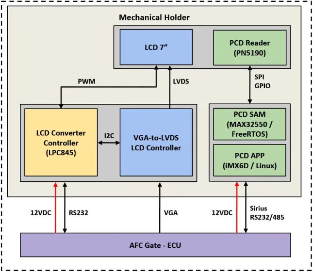
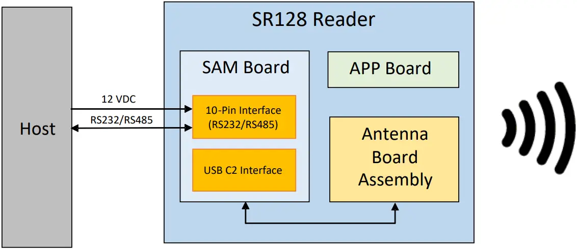
Figure 1. System overview
2.2. PCD Module
2.2.1. PCD-APP board interfaces
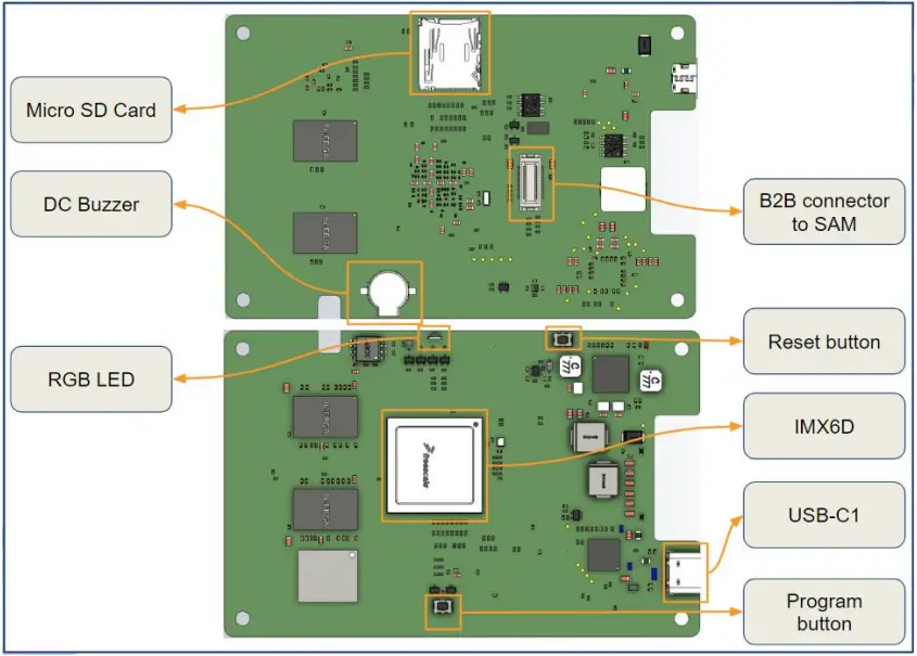
Figure 2. PCD-APP board PCB with main connector pinout
Table 1. PCD-APP board PCB main connectors
| Connector | Function |
| USB-C1 Connector | USB interface to HOST Support USB 2.0 data only |
| B2B connector | APP board to SAM board connection |
2.2.2. PCD-SAM board interfaces
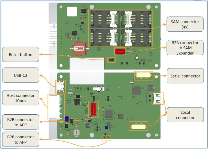
Figure 3. PCD-SAM board PCB main connector
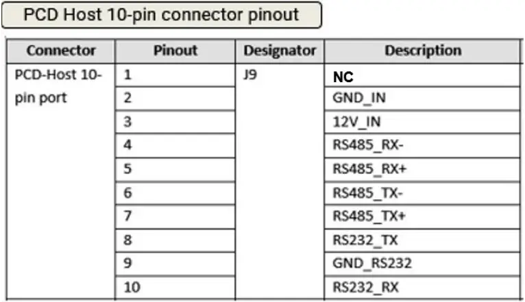
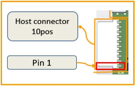
Figure 4. PCD-HOST 10 Pins – main connector pin out configuration
Table 2. PCD-APP board PCB main connectors
| Connector | Function |
| USB-C2 Connector | USB interface for reader operating in PCSC/CCID mode |
| B2B connector | For expansion to 8 SAM |
| PCD-Host 10-pin conn | Reader power input and RS232/485 connectivity to HOST |
| PCD-Reader Antenna conn | Connection to Antenna |
2.2.3. PCD-Antenna board interfaces
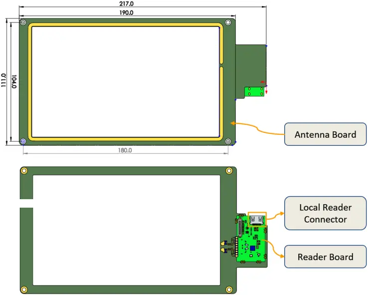
Figure 5. PCD-Reader-Antenna board PCB
Table 3. PCD-READER ANTENNA board PCB main connector
| Connector | Function |
| PCD-Reader Antenna conn | Antenna connection to reader |
2.3. Assembly
2.3.1. Contactless Product Assembly
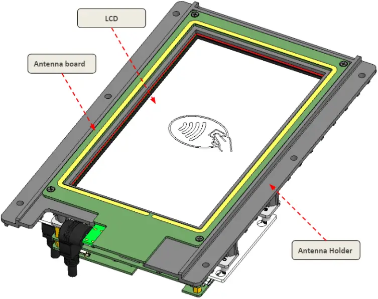
Figure 6. Top view
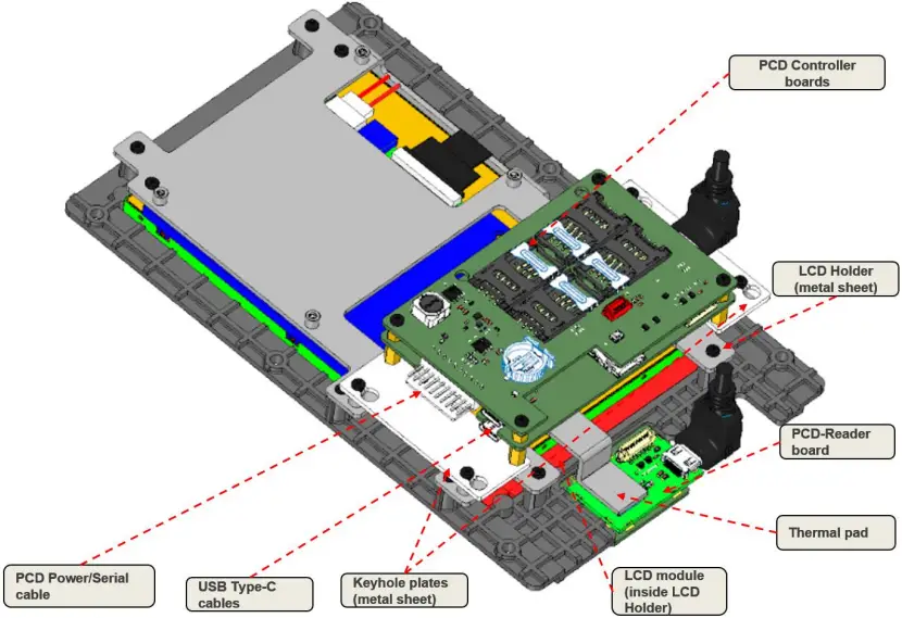
Figure 7. Bottom view
2.3.2. Physical dimension
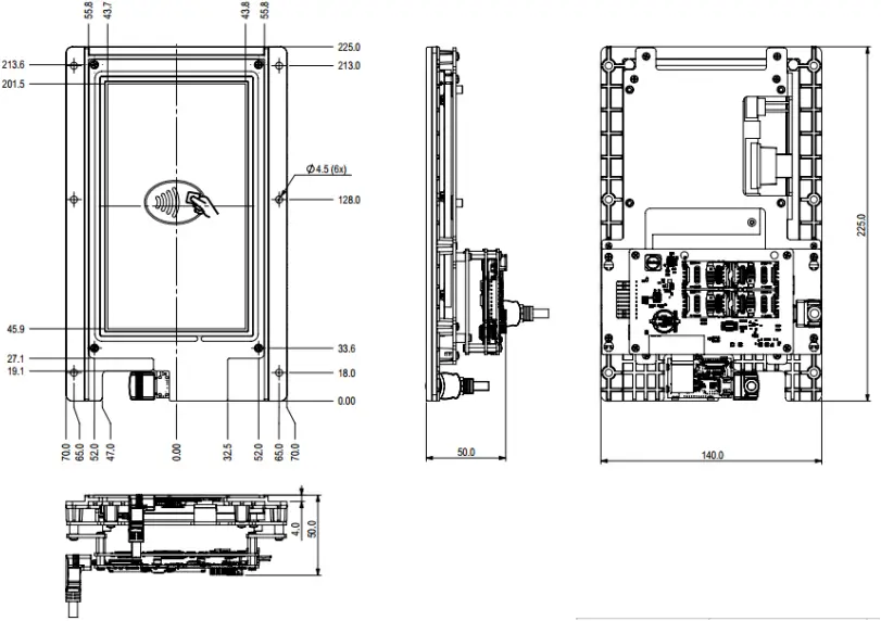
Figure 8. Physical dimension without cables
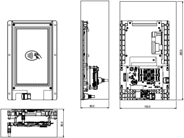
Figure 9. Physical dimension with cables
3. Specifications
3.1. Operating Conditions
| No. | Specification | Type | Min. | Typ. | Max. | Unit | Remarks |
| 1 | Temperature | Operating | -10 | – | +60 | °C | |
| 2 | Temperature | Storage | -20 | – | +85 | ° C | |
| 3 | Humidity | Relative | 0 | – | 95 | % | non-condensing |
3.2. Power Supply
| No. | Specification | Type | Min. | Typ. | Max. | Unit | Remarks |
| 1 | 10 Pin Connector | Voltage | – | 12 | – | VDC | |
Current | – | – | 650 | mA | |||
| 2 | USB C1 | Voltage | – | 5 | – | VDC | |
Current | 500 | 900 | mA | 500mA (for USB2.0) or 900mA (for USB3.1) | |||
1500 | mA | USB PD support | |||||
| 3 | USB C2 | Voltage | – | 5 | – | VDC | |
Current | 500 | 900 | mA | 500mA (for USB2.0) or 900mA (for USB3.1) |
3.3. Processors and Controller
| No. | Specification | Description |
| 1 | Processor | Application: iMX6 dual-core ARM Cortex-A9 800MHz RF: Maxim Secure ARM Cortex-M3 108MHz |
| 2 | Memory | 2GB DDR RAM and 4GB NAND Flash |
3.4. Indicator
| No. | Specification | Description |
| 1 | LED Indicators | Power LED, RGB status LED |
| 2 | Alert | DC Buzzer |
3.5. PCD
| No. | Specification | Description |
| 1 | Carrier Frequency | 13.56MHz |
| 2 | Standard compliance | ISO/IEC 14443-1 to 14443-4 Type A & B ISO/IEC 15693 Sony Felica™ ECMA-340, ECMA-352 and ISO18092 |
| 3 | Baud-rate | 106kbps, 212kbps, 424kbps, 848kbps |
| 4 | Card type supported | All ISO 14443-X contactless cards |
| 5 | Communication Range | CPU-based card: up to 8.5cm Memory-based card: up to 10cm |
3.6. Data Communication Interface
| No. | Specification | Description |
| 1 | USB interface | USB Type C |
| 2 | Serial interface | RS232/422/485 Baud-rate configurable 9600, 19200, 115200 and 230400 kbps |
3.7. Standards & Certification
| No. | Specification | Description |
| 1 | EMC | EN50121-4 – Railway applications |
| 2 | Regulatory | CE / FCC approved |
| 3 | EMV | EMV L1 v3.1a VISA payWave L2 VCPS v2.2c and VCTKS 1.1a MasterCard PayPass L2 v3.1.4 |
| 4 | Shock | Acceleration: 20g, Pulse duration: 11ms, Direction: 3 perpendicular axes, No of shocks: 5 per axes |
| 5 | Vibration | IEC-68 part 2-31 and DIN EN 60721-3-5 class 5M2 |
4. Reader Connection
The SR128 reader interfaces with the host via the 10pin serial and power connection when operating host-reader configuration.
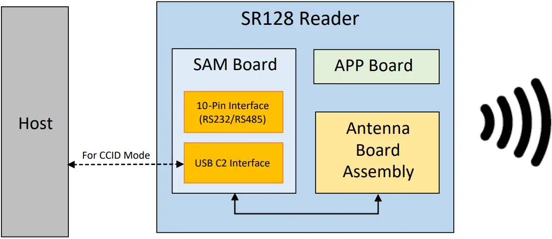
In PCSC/CCID mode, the host can connect to the reader using the USB-C2 interface. The reader will present itself as a standard PCSC reader to the Operating System.
5. Installing and Replacing SAM card
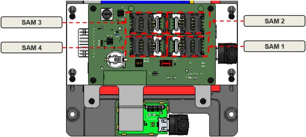
Figure 10. SAM cards position in bottom view
- Installing and Uninstalling SAM card
Step 1: Push the metal lock of the sim towards the arrow
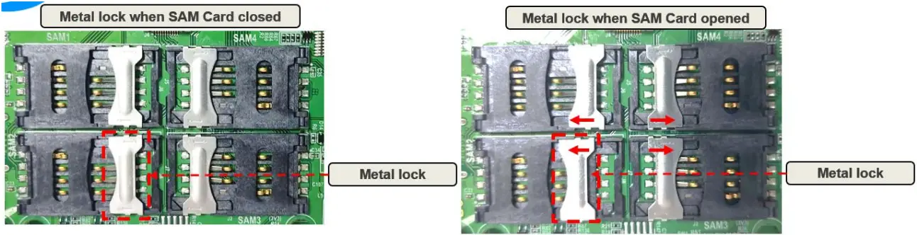
Step 2: Open the cover and insert the SAM card inside and then close the cover and wipe the metal lock towards the arrow
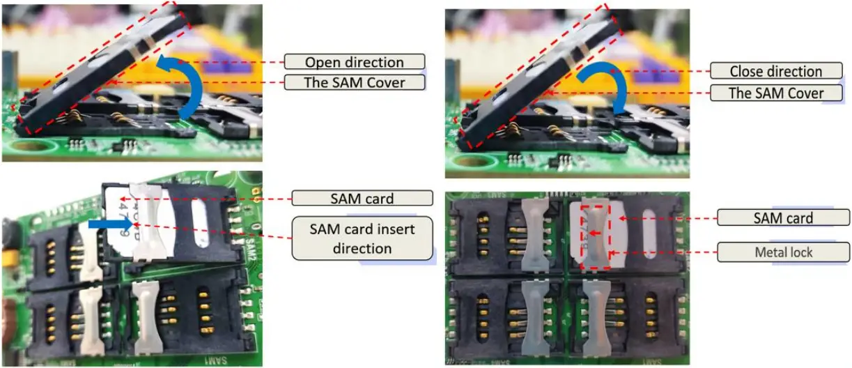
Step 4: Reversed the Step to take out the SAM Card.
6. Operational Precautions
6.1. General Safety Instructions
The SR128 reader contains ESD sensitive components. When handling with the device, avoid in contact with components especially the ICs on the boards. The operating voltage of the SR128 reader has 12VDC. The 10pin connector accepts 12VDC. Operating the SR128 reader other than the rated voltage will experience performance deterioration or damage the reader.
6.2. Installation
The SR128 Reader uses inductive coupling to communicate with contactless cards. Therefore, the reader is highly sensitive to ferrous or non-ferrous metal alike. Installation near to metal may affect operating distance. It is important to keep a comfortable distance away these metal surfaces for optimum performance.
6.3. Reader Status Indicators
There are LED indicators and DC Buzzer located on Reader module APP/SAM boards for various Reader status indicators.
No | Color | Freq (Hz) | Meaning |
1 | WHITE | 0 | No Error |
2 | RED | 5 | Power Supply OVER 12V |
3 | GREEN | 5 | Power Supply UNDER 12V |
4 | YELLOW | 5 | PN5190 NO RESPONSE |
5 | BLUE | 5 | SAM NO RESPONSE |
6 | PURPLE | 5 | TEMP SENSOR NO RESPONSE |
7 | CYAN | 5 | TEMP SENSOR OVERHEAT |
8 | RED | 0 | ANTENNA DETUNED |
9 | GREEN | 0 | RF PROCESS RAM CHECK FAILED |
10 | YELLOW | 0 | RF PROCESS NO RESPONSE |
No | Color | Meaning | |
1 | RED | Remaining | NO ERROR |
2 | RED | Blinking | USB CCID mode |
3 | OFF | SAM Board cannot boot |
6.4. Battery Safety Information
CAUTION
RISK OF EXPLOSION IF BATTERY IS REPLACED BY AN INCORRECT TYPE.
DISPOSE OF USED BATTERIES ACCORDING TO THE INSTRUCTIONS
a. Use only CR1220, BATTERY LITHIUM COIN 3V 20MM. Observe the following guidelines for safe use of Li Ion batteries.
b. Do not expose the battery to excessive heat or cold. Do not short-circuit. It may explode.
c. To avoid risk of fire, burn or damage to your battery, do not allow a metal object to touch battery contacts.
d. Do not disassemble the battery. There are no user serviceable parts inside.
e. If battery leakage is observed, avoid any contact with affected area and properly dispose of the battery.
f. If you come in contact with battery leakage, rinse exposed area with soap and water. If it contacts the eye, flush the eye with water for 15 minutes and seek medical attention.
g. When discarding a battery, contact your local waste disposal provider to understand local restrictions for disposal or recycling of batteries.
6.5. Fuse Information
This product contains Fuses in its circuit. The Fuse part numbers are 1206L150/12SLYR; PTC RESET FUSE 12V 1.5A 1206 (Littelfuse).
7. FCC Compliance Statement
This device complies with part 15 of the FCC Rules. Operation is subject to the following two conditions: (1) This device may not cause harmful interference, and (2) this device must accept any interference received, including interference that may cause undesired operation.
Note: This equipment has been tested and found to comply with the limits for a Class B digital device, pursuant to part 15 of the FCC Rules. These limits are designed to provide reasonable protection against harmful interference in a residential installation. This equipment generates, uses and can radiate radio frequency energy and, if not installed and used in accordance with the instructions, may cause harmful interference to radio communications. However, there is no guarantee that interference will not occur in a particular installation. If this equipment does cause harmful interference to radio or television reception, which can be determined by turning the equipment off and on, the user is encouraged to try to correct the interference by one or more of the following measures:
- Reorient or relocate the receiving antenna.
- Increase the separation between the equipment and receiver.
- Connect the equipment into an outlet on a circuit different from that to which the receiver is connected.
- Consult the dealer or an experienced radio/TV technician for help.
Important: Caution: Any changes or modifications not expressly approved by the party responsible for compliance to this equipment would void the user’s authority to operate this device.
© Copyright 2022 STYL Solution Pte., Ltd., All rights reserved


