![]()
www.jbctools.com
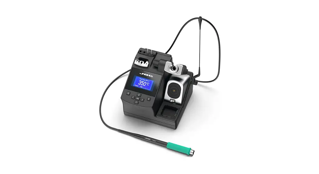
INSTRUCTION MANUAL
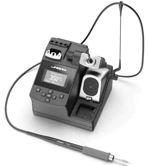
Compact Soldering Station
Ref. CD-BQF
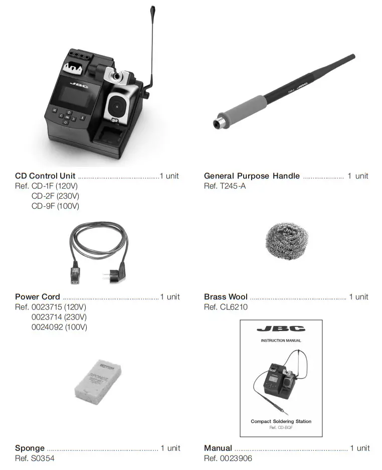
Packing List
The following items are included:
Features and Connections
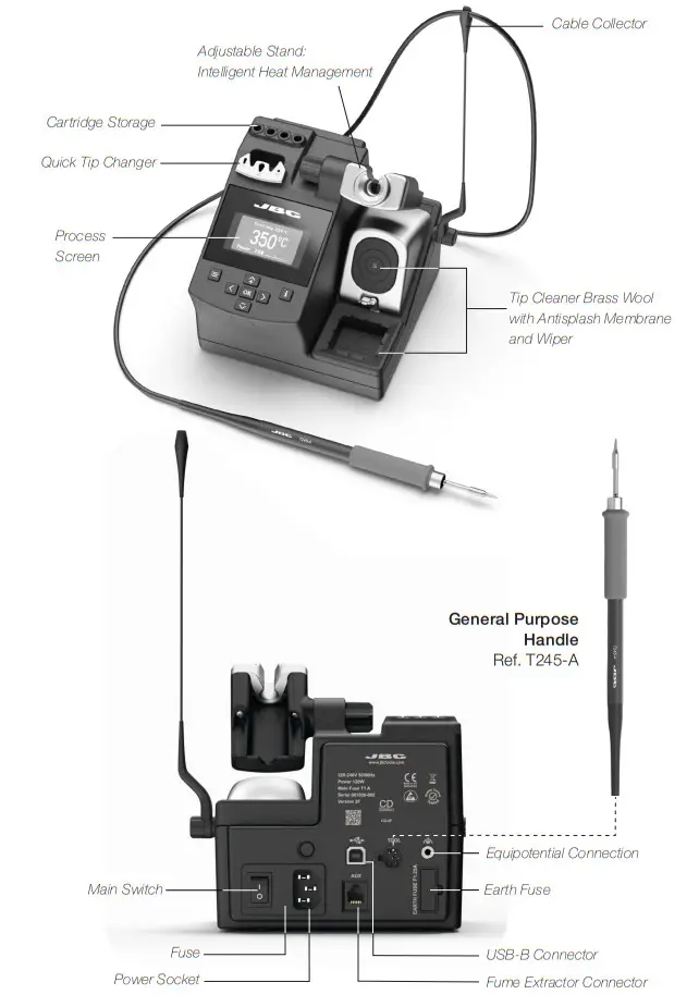
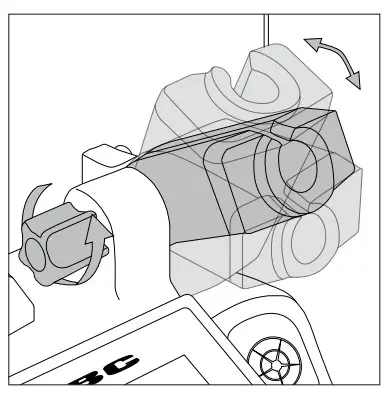
Adjustable Stand
Adjust the tool stand to suit your work position.
Cable Collector (Ref. CC1001)
The Cable Collector keeps the cable away from the work area and prevents that the weight of the cable from disturbing the operator while soldering.
| Insert the cable into the clip and then insert it into the Cable Collector. Do not leave the cable longer than necessary to reach the work area freely. | 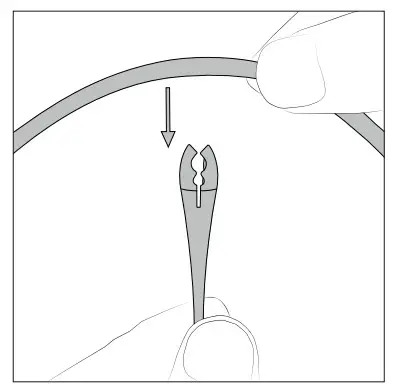 | The Cable Collector is flexible. It accompanies and adapts to the movements during the soldering process. | 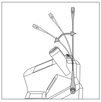 |
Tip Cleaner
Select the option to suit your needs and improve the thermal transfer of the tip.
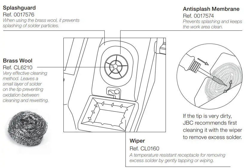
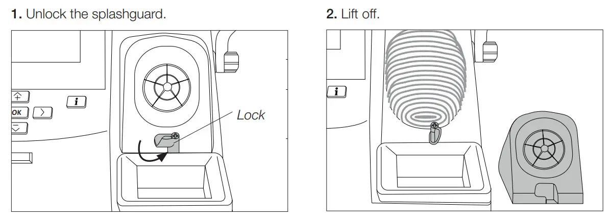
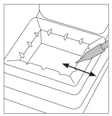
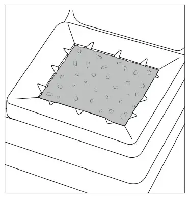
Removing the Splashguard
More cleaning options (not supplied):
| Inox Wool Ref. CL6205 Stronger cleaning method than brass wool. | 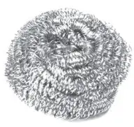 | Metal Brush Ref. CL6220 When used carefully, it provides a more thorough Cleaning. | 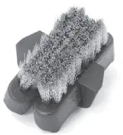 |
Wiper
Ref. CL0160
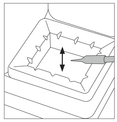
Tapping:
Tap gently to remove excess solder.
Wiping:
Use the slots to remove the remaining particles.
Sponge
Ref. S0354
The softest cleaning method. Keep the sponge damp with distilled water when working to avoid tip wear.
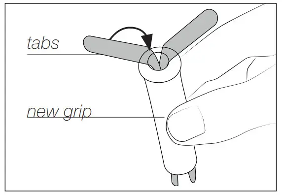
Changing the Grips
Easily replace the grips using the slip-on tabs. Note: For the different handles are different grips available.
| Handels: | T245-A / T245-C / T245-GA | T210-A / T210-NA | T245-PA | T210-PA |
| Grip ref.: | 0016057 (green) | 0018658 (green) | 0021528 (blue) | 0023310 (blue) |
- Inserting Tabs
 Put the slide-on tabs into the new grip.
 - Inserting Handle

Push the grip with the tabs onto the handle. - Removing Tabs
 Hold the grip and pull the tab. Use pliers if necessary.
 Put the slide-on tabs into the new grip.
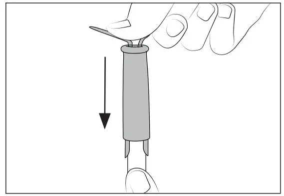
 Hold the grip and pull the tab. Use pliers if necessary.
Sealing Plug Replacement
The sealing plug prevents undesirable flux vapors or particles from entering inside the tool. Its usage is highly recommended for intensive applications when soldering is exposed to FOD environments or for applications where the soldering iron works close to a vertical position.
Note: For the different handles are different sealing plugs available.
| Handels: | T245 / T470 | T210 |
| Sealing plug ref.: | OB2000 | OB1000 |
 Before replacing the sealing plug, unplug the power supply and make sure the device is not hot.
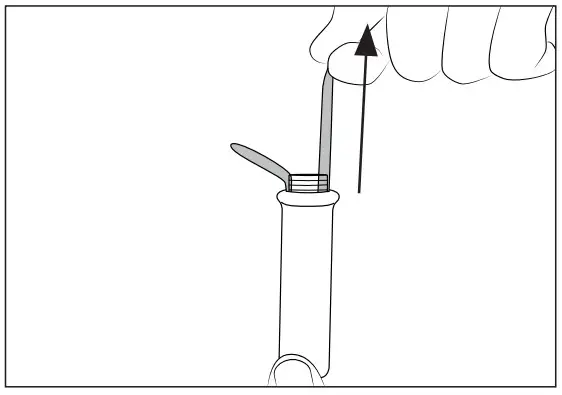
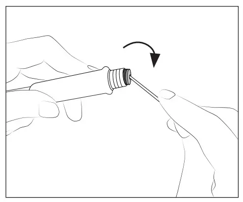
- Removing Sealing Plug
 Enter, not deeper than 8mm, a small shaft or screwdriver and lift and pull the sealing plug. Never use a cartridge to do this operation.
 - Mounting Position
 Note: The chamfered side has to be positioned towards the handle.
 - Inserting Sealing Plug
 Push the sealing plug inside the handle until the sealing plug and handle edges are aligned.
 Enter, not deeper than 8mm, a small shaft or screwdriver and lift and pull the sealing plug. Never use a cartridge to do this operation.
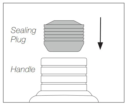 Note: The chamfered side has to be positioned towards the handle.
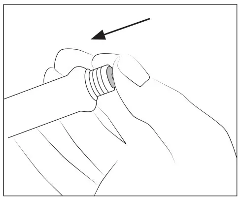 Push the sealing plug inside the handle until the sealing plug and handle edges are aligned.
Quick Tip Changer
Save time and change cartridges safely without switching the station off.
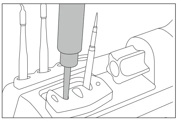
- Removing
 Place the handpiece in the extractor and pull to remove the cartridge.
 - Inserting
 Place the handpiece on top of the new cartridge and press down slightly.
 - Fixing
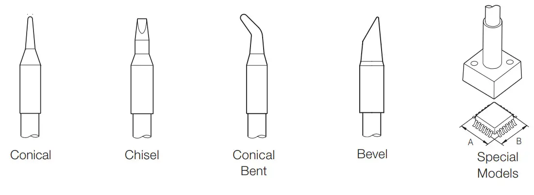
 Use the holes for fixing the cartridge* as follows: A. For straight C210. B. For curved C210. C. For C245.
 Place the handpiece in the extractor and pull to remove the cartridge.
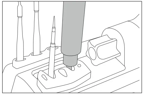 Place the handpiece on top of the new cartridge and press down slightly.
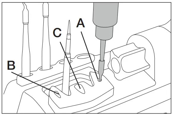 Use the holes for fixing the cartridge* as follows: A. For straight C210. B. For curved C210. C. For C245.
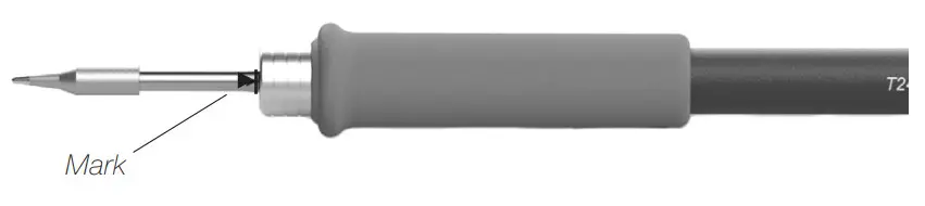
*Important: It is essential to insert the cartridges as far as the mark for a proper connection.
Compatible Cartridges
The CD-B stations work with C245 cartridges and T245 handles. Find the model that best suits your soldering needs at www.jbctools.com
Operation
The JBC Most Efficient Soldering System
This revolutionary technology is able to recover tip temperature extremely quickly. This allows the user to work at a lower temperature. As a result, tip life increases by 5.
Through menu settings:
- Select temperature levels
- Fix one temperature
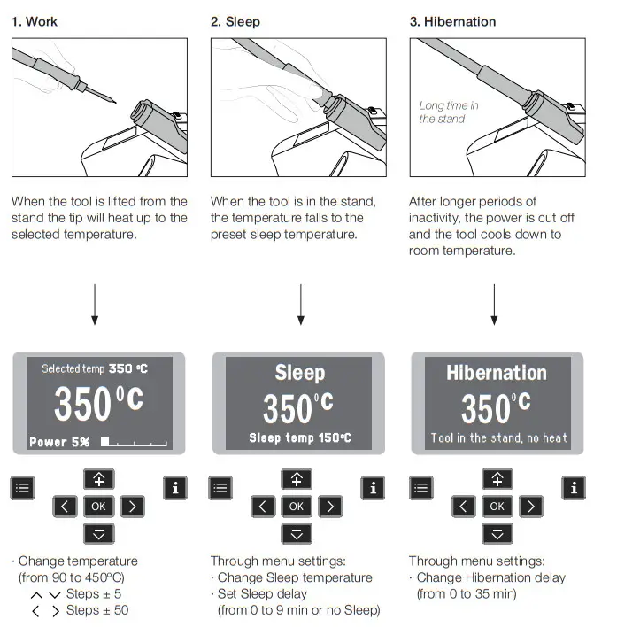
Control Process
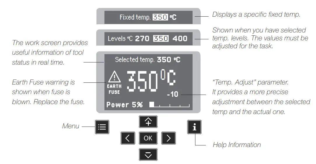
Work Screen
Menu Screen
Troubleshooting
Station troubleshooting is available on the product page at www.jbctools.com
Parameters
Be careful when using these parameters as they may reduce the tip life if not used properly. Please follow the recommended guidelines:
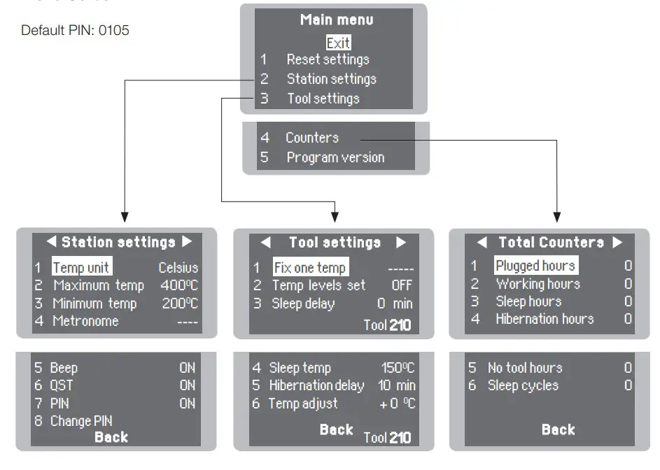
Station Settings
| Parameter Description | Recommendations | Warnings |
| Temperature Unit Celsius (ºC) or Fahrenheit (ºF) N/a | ||
| Maximum Temperature Set the maximum temperature to work with. Max. temp by default is 400°C (750°F). This is considered high enough to work with most lead-free applications. | The station temperature range is 90-450ºC (190-840ºF). Change the temperature limits when working with less common applications such as low/high melting point soldering (HMP) or plastics (e. g. riveting). | |
| Minimum Temperature Set the minimum temperature to work with. Min. temp. by default is 200ºC (392ºF). This is considered to be a proper starting point for leaded applications. | ||
| Metronome This activates a beep sound. Frequencies vary from 1 to 50 seconds. | Useful for setting a work rate in repetitive jobs. The beep lets you know the length of time the tip must be in contact with the soldering joint. | N/a |
| Beep Enable/disable the beep sound of the keypad. | N/a | N/a |
| QST Enable/disable QST. | N/a | N/a |
| Pin Enable/disable pin prompt. | N/a | N/a |
| Change Pin Change the default security PIN number (0105). | The PIN must be entered every time a parameter is changed. | N/a |
Tool Settings
| Parameter Description | Recommendations | Warnings |
| Fix One Temperature Fix a value within the temperature range of the station (90-450ºC/190-840ºF). | Ideal for soldering more than one component at a specific temperature. The station will reject any attempt to change the temperature. | N/a |
| Temperature Levels Set Similar to the “Fix one temp” parameter. In this case, the user can set up to 3 values for different power requirements. | This allows a quick change between 3 different temperatures. Set them according to the allowed values for your soldering applications. | N/a |
| Sleep Delay Set the time that the tool will remain at the selected temperature when in the stand before entering sleep mode. The tip temperature will then drop to the Sleep temperature. | Because our tools reach the working temperature from the default Sleep mode in only a few seconds, this parameter is preset to 0 min. Once the tool is returned to the stand the temperature will automatically drop to the sleep temperature extending tip life and avoiding oxidation. Retinning the tip before placing the tool in the stand will protect the tip and extend its life. | |
| Sleep Temperature This is the set temperature the tip reaches when returned to the stand. | The sleep temperatures are set to achieve a balance between preventing oxidation and reaching the working temperature in a few seconds. | |
| Hibernation Delay Set the time the tool will remain at Sleep temperature before entering the Hibernation mode. At this time, the power supply is cut off and the tip remains at room temperature. | This function completely protects the tip from oxidation during long periods of inactivity while the tool is in the stand. Retinning the tip before placing the tool in the stand also helps prevent oxidation and extends the life of the tip. | |
| Temp Adjustment It provides a more precise adjustment between the selected temperature and the actual one. | Set values within ±50°C (± 90°F) to achieve zero error. JBC strongly recommends the use of TID-A or TIA-A Thermometers to obtain precise readings. | |
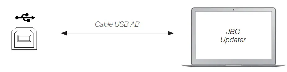
USB Connector
Download the latest software from our website to improve your soldering station.
JBC Updater
www.jbctools.com/software.html
Update the station software via USB connection:
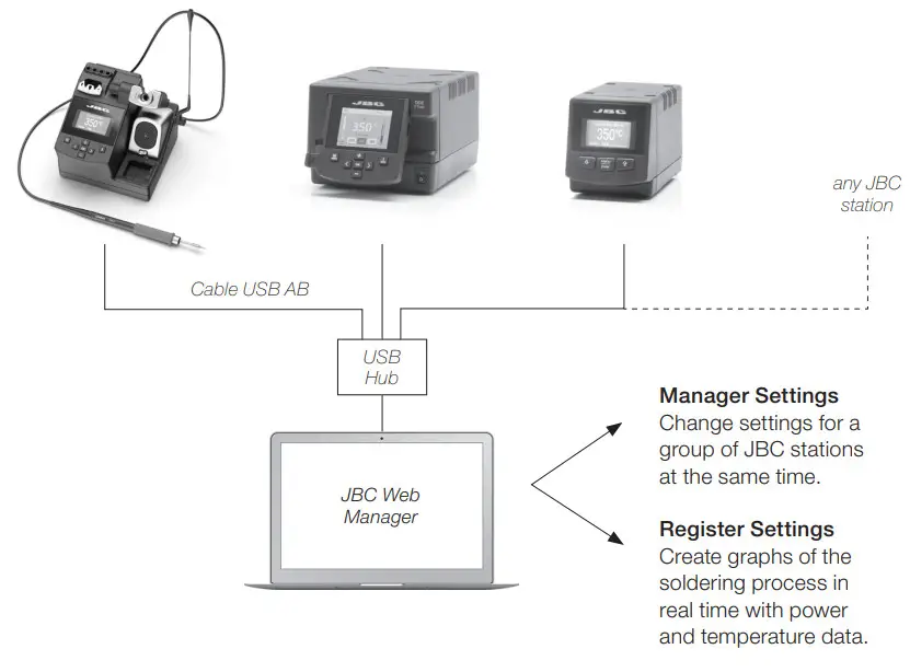
JBC Web Manager
www.jbctools.com/manager.html
Manage and monitor as many stations as your PC can handle by using the JBC Web Manager. You can export data to another PC.
 Maintenance
 Maintenance
Before carrying out maintenance, always switch the device off and disconnect it from the mains. Allow the equipment to cool down.
– Clean the station screen with a glass cleaner or a damp cloth.
– Use a damp cloth to clean the casing and the tool. Alcohol can only be used to clean the metal parts.
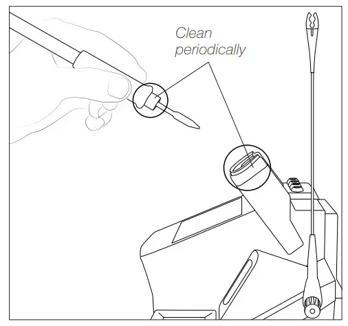
– Periodically check that the metal parts of the tool and stand are clean so that the station can detect the tool status.
– Maintain tip surface clean and tinned prior to storage in order to avoid tip oxidation. Rusty and dirty surfaces reduce heat transfer to the solder joint.
– Periodically check all cables and tubes.
– Replace any defective or damaged pieces. Only use original JBC spare parts.
– Replace a blown fuse as follows:
- Pull off the fuse holder and remove the fuse. If necessary use a tool to lever it off.
- Insert the new fuse into the fuse holder and return it to the station.

– When this warning appears on the main screen Earthing Fuse must be replaced
 | 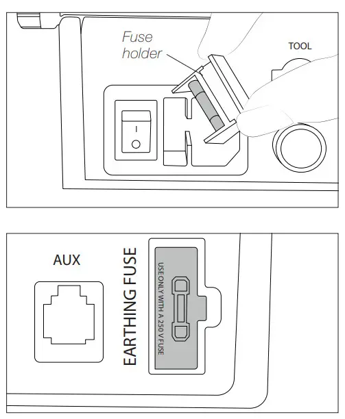 |
– Repairs should only be performed by a JBC authorized technical service.
Safety
![]() It is imperative to follow safety guidelines to prevent electric shock, injury, fire, or explosion.
It is imperative to follow safety guidelines to prevent electric shock, injury, fire, or explosion.
– Do not use the units for any purpose other than soldering or rework. Incorrect use may cause a fire.
– The power cord must be plugged into an approved basis. Be sure that it is properly grounded before use. When unplugging it, hold the plug, not the wire.
– Do not work on electrically live parts.
– The tool should be placed in the stand when not in use in order to activate the sleep mode. The soldering tip, the metal part of the tool, and the stand may still be hot even when the station is turned off. Handle with care, including when adjusting the stand position.
– Do not leave the appliance unattended when it is on.
– Do not cover the ventilation grills. Heat can cause inflammable products to ignite.
– Avoid flux coming into contact with skin or eyes to prevent irritation.
– Be careful with the fumes produced when soldering.
– Keep your workplace clean and tidy. Wear appropriate protection glasses and gloves when working to avoid personal harm.
– Utmost care must be taken with liquid tin waste which can cause burns.
– This appliance can be used by children over the age of eight and also persons with reduced physical, sensory or mental capabilities or lack of experience provided that they have been given adequate supervision or instruction concerning the use of the appliance and understand the hazards involved. Children must not play with the appliance.
– Maintenance must not be carried out by children unless supervised.
Specifications
CD-1BQF 120V 50/60Hz. Input fuse: T2A. Output: 23.5V. Control Unit model: CD-1F
CD-2BQF 230V 50/60Hz. Input fuse: T1A. Output: 23.5V. Control Unit model: CD-2F
CD-9BQF 100V 50/60Hz. Input fuse: T2A. Output: 23.5V. Control Unit model: CD-9F
| – Output Peak Power CD-BF: | 130W |
| – Temperature Range: | 90 – 450 °C / 190 – 840 °F |
| – Idle Temp. Stability (still air): | ±1.5ºC (±3ºF) / Meets and exceed IPC J-STD-001 |
| – Temp. accuracy: | ±3% (Using reference cartridge) |
| – Temp. adjustment: | ±50ºC / ±90ºF (Through station menu setting) |
| – Tip to ground voltage/resistance: | Meets and exceed ANSI/ESD S20.20-2014 IPC J-STD-001F |
| – Earthing Fuse: | F 1.25A |
| – Connections: | USB connector station-PC RJ12 Connector |
| – Ambient operating temp: | 10 – 50 ºC / 50 – 122 ºF |
| – Control Unit Dimensions / Weight: (L x W x H)
| 170 x 176 x 145 mm / 2.8 kg 6.7 x 9.7 x 5.7 in / 6.17 lb |
| – Total Net Weight: | 3 kg / 6.61 lb |
| – Total Package Dimensions / Weight:(L x W x H)
| 234 x 234 x 258 mm / 3.15 kg 9.2 x 9.2 x 10.2 in / 6.94 lb |
Complies with CE standards
ESD protected housing “skin effect”
![]()
Warranty
JBC’s 2-year warranty covers this equipment against all manufacturing defects, including the replacement of defective parts and labor. Warranty does not cover product wear or misuse. In order for the warranty to be valid, equipment must be returned, postage paid, to the dealer where it was purchased.
Get 1 extra year JBC warranty by registering here:
https://www.jbctools.com/productregistration/
within 30 days of purchase.
 This product should not be thrown in the garbage. In accordance with the European directive 2012/19/EU, electronic equipment at the end of its life must be collected and returned to an authorized recycling facility.

![]()
0023906-0121


