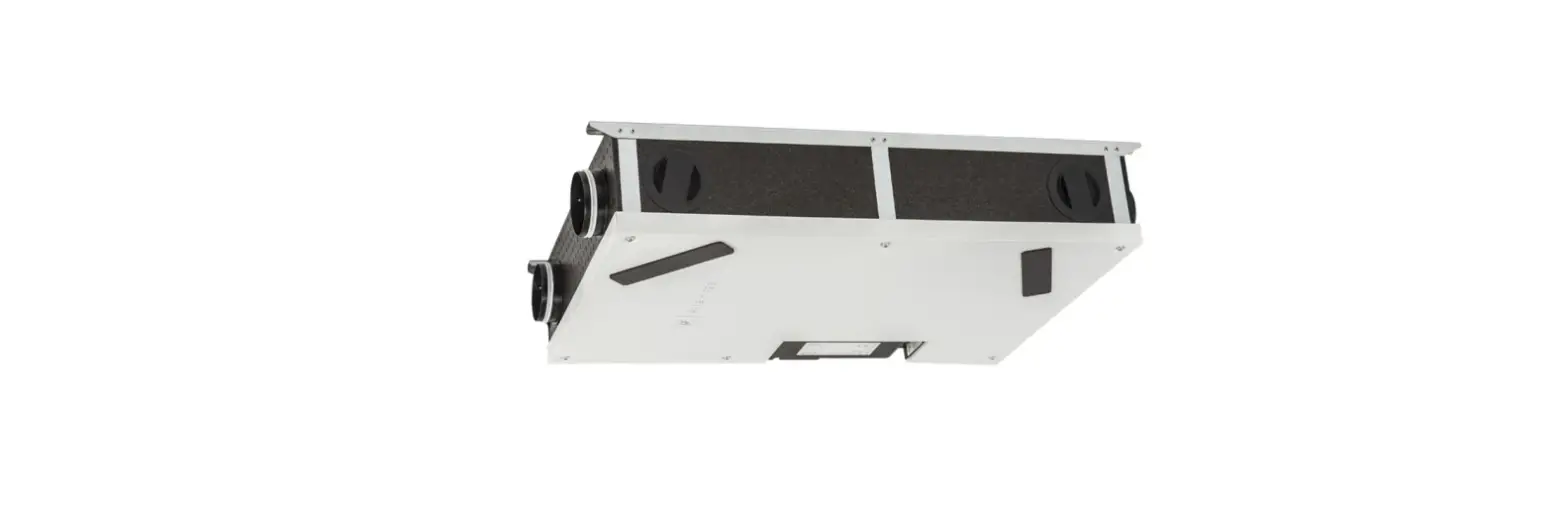
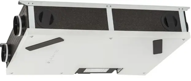
S P ALTAIR 120 H False Ceiling Mounting
OVERVIEW
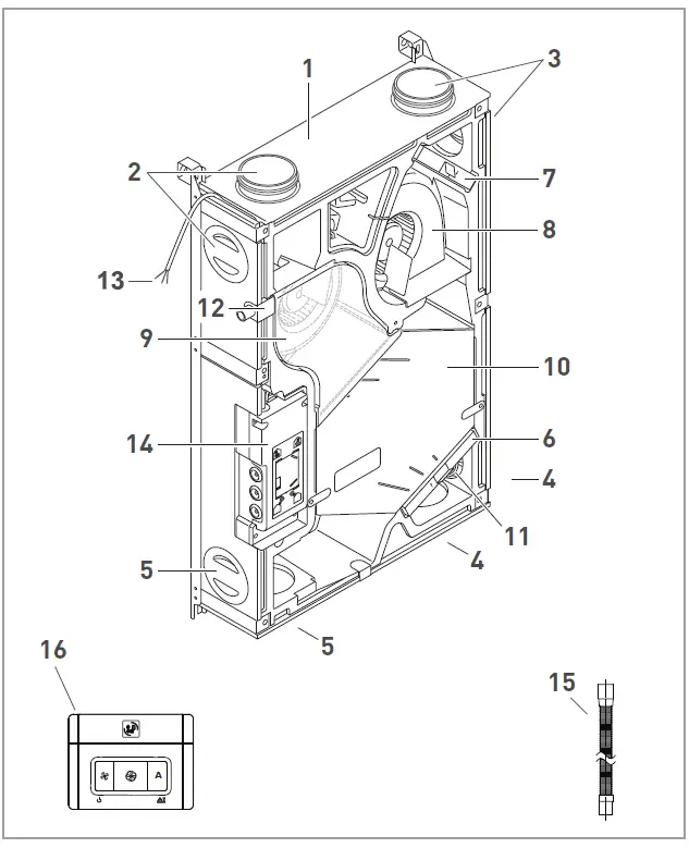
- Heat recovery unit ALTAIR
- Exhaust air (EHA)
- Outdoor air (ODA)
- Extract air (ETA)
- Supply air (SUP)
- G4 filter (extract air)
- G4 filter (outdoor air)
- Supply air fan
- Exhaust air fan
- Counterflow heat exchanger
- Humidity sensor
- Condensation water connection
- Power supply cable
- Control
- Drain duct (l=150mm)
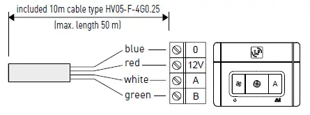
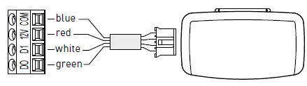
- Remote control (inlcudes 10m cable)
GENERAL
WARNINGS
This product was manufactured according to rigorous technical safety rules in compliance with DC standards. The DC declaration and the manual can be downloaded from the Internet. Before installing and using this product, carefully read these instructions, which contain important indications to ensure your safety and that of the users during the installation, commissioning and servicing of this product. Once the installation is terminated, leave this manual in the machine for future consulting. The installation of this product (implementation, connections, commissioning, maintenance) and all other interventions must be performed by a professional, applying the recognized rules of good practice, standards and safety regulations in force. It must conform to the prescriptions related to Electromagnetic Compatibility (EMC) and the Low Voltage Directive (LVD). S&P shall not be held responsible for possible injuries and/or damages caused by the non compliance with safety instructions or following a modifi cation of the product. This appliance is considered to be suitable for use in countries having a warm damp equable climate as spe-cifi ed in IEC 60721-2-1. It may also be used in other countries.
Indoor installation:
- Minimum recommended ambient temperature for the unit +10ºC.
- Limits, ambient temperature min. +10ºC and max. +50ºC.
- Limits, air temperatures -18ºC and +50ºC.
- Relative humidity: max 95% non condensing.
- Atmosphere not potentially explosive.
- Atmosphere with low salt content, without corrosive chemical agents.
Means for disconnection must be incorporated in the fixed wiring according with the wiring rules. An external disconnecting device, which will function as the “designated” disconnect device must be provided, and:
- It shall disconnect the “Line”, while disconnection of the “Neutral” is optional;
- Its OFF-position shall be clearly marked;
- Not to position the equipment so that it is difficult to operate it; and
- The protection current device must be at least 16A, 250V, curve Type C.
- The device must be powered via a differential switch (RCD) with a rated residual operating current not exceeding 30 mA.
If the supply cord is damaged, it must be replaced by the manufacturer, its service agent or similar qualifi ed persons in order to avoid a hazard.
SAFETY INSTRUCTIONS
This appliance can be used by children aged from 8 years and above and persons with reduced physical, sensory or mental capabilities or lack of experience and knowledge if they have been given supervision or instruction concerning use of the appliance in a safe way and understand the hazards involved. Children shall not play with the appliance. Cleaning and user maintenance shall not be made by children without supervision.
- Wear appropriate IPE (Individual Protection Equipment) before any intervention.
- Before installing the unit, make sure that the support and placement are sufficient resistant to withstand the units weight.
- Do not open the access doors without first switching off the electrical power supply.
- If the work is to be performed inside the device, switch off the electrical power supply on the main circuit breaker and make sure that no one can accidentally switch it on.
- Make sure that the moving parts are stopped.
Before starting, check the following points:
- Make sure that the device does not contain any foreign body.
- Make sure that all the components are attached in their original placements.
- Check the earthing connection.
- Precautions must be taken to avoid the back-fl ow of gases into the room from the open flue of gas or other fuel-bur-ning appliances (for duct and partition fans).
ACCEPTANCE – STORAGE
In case of missing, non-conforming, or totally or partially damage delivered products, the purchaser must make written reservation on the transporters receipt and confi rm them within seventy-two (72) hours by sending a recommended letter to the transporter, as well as a copy to S&P. Acceptance of the unit without any reservation will deprive the purchaser of anys. The product must be stored in an area protected from bad weather, shock and stains due to splashing or splattering of any kind during its transport from the supplier to the end customer and onto the worksite before installation.
WARRANTY
The unit supplied by S&P is warranted 24 months, parts only, starting from the invoicing date. S&P agrees to replace the parts or the unit whose operation is recognized defective by our departments except for all damages and interests or penalties such as operating losses, commercial prejudice, or other immaterial or indirect damages. The following are not covered by our warranty: defects resulting from an abnormal usage or a usage not conforming to the recommendations of our manuals; faults observed as a consequence to normal wear; incidents caused by negligence, lack of monitoring, or servicing; faults due to the incorrect installation of the devices or to bad storage conditions before mounting.
In any case, S&P will not be responsible for transformed unit, repaired even partially.
TECHNICAL INFORMATION
GENERAL INFORMATION
The ALTAIR ensures optimum ventilation of a house with a maximum energy recovery. It draws air from the rooms (bathroom(s), toilet, kitchen and wash room(s)) and supplies fresh air through the main rooms (living room, bedroom (s), offi ce, etc ).
The fresh and extract airflows are separated and filtered. Only heat energy is transferred to the fresh filtered air that is introduced. Due to the high-efficiency heat exchanger used in the ALTAIR performance can reach 86%.
Condensation forms during the heat exchange process and is recovered in the condensate tray, which must be connected to a waste water drain.
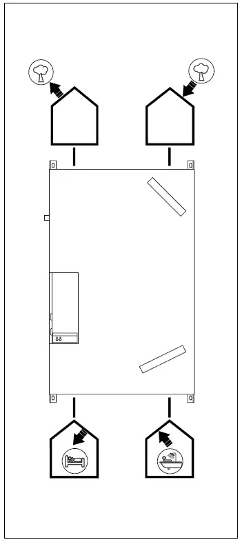
 Outdoor air (ODA):
Install the fresh air intake (wall or roof) at a sufficient distance from any source of high pollution (trees, exhaust fumes, roads, etc.) This duct must be sealed and insulated to prevent condensation. Supply air (SUP):
To avoid thermal losses and optimize the performance of the installation, it is recommended to use insulated duct. Extract air (ETA):
To avoid thermal losses and optimize performance of the installation, it is recommended to use insulated ducts. Exhaust air (EHA):
This duct must be sealed and insulated to prevent condensation. This duct must be sealed and insulated to prevent condensation.
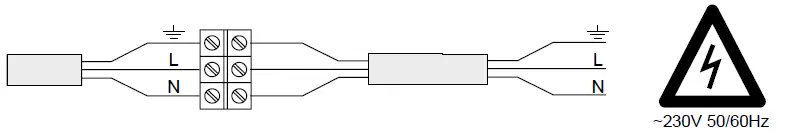
DIMENSIONS AND ELECTRIC CONNECTION
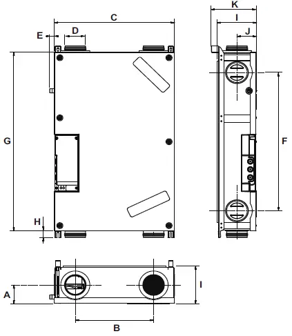
| A | 90 mm |
| B | 360 mm |
| C | 550 mm |
| D | 94 mm |
| E | 30 mm |
| F | 660 mm |
| G | 850 mm |
| H | 30 mm |
| I | 178 mm |
| J | 91 mm |
| K | 208 mm |
REMOTE CONTROL
 SPCM-1 (optional)
INSTALLATION
To avoid the vibration transmission and noise to the duct, we recommend to use flexible connections.
- Supply/Extract Air: Installation of flexible silencers type LAF 95 (article code: 5209358600 / LAF 95 0,5M or 5209358500 / LAF 95 1M)
- Outdoor/Exhaust Air: connection with flexible duct thermally insulated type GP ISO ECOSOFT (article number: 5209346600 GP-ISO 100/25 6M ECOSOFT
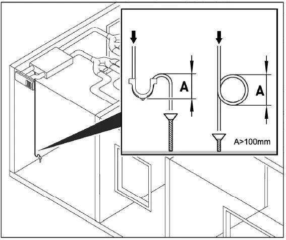
The drain pipe should be installed with a drop of min. 1% to assure a good drainage and has to be connected to a with water filled siphon. Please assure that the access opening to the unit is big enough to allow maintenance or replacing the unit.
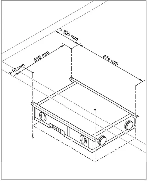
- It is recommended to install the ALTAIR in the heated zone of the house. The minimum temperature should not be less than +10ºC.
- In climate zones where outdoor temperatures are often under -10ºC it is recommended to install a pre-heater.
- The ALTAIR heat recovery unit is designed for indoor installation
START UP
Installer
The remote control allows to adjust:
- Airflows (3 speeds)
- Period for filter maintenance
- Balance of supply/extract airflow
To adjust the speed please turn the corresponding potentiometer with a small screw driver in the wished position. The ALTAIR 120 is working with constant airflow. This allow to adjust the airflow as in the tables below without the necessity to balance. The potentiometer “balance airflows” allows to work in over/under pressure if wished.
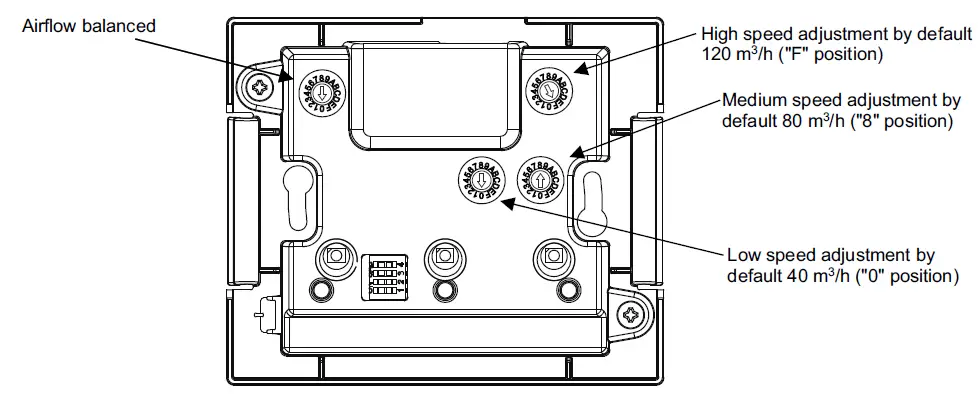
Airflow adjustment
| low speed | ||||||||||||||||
| Potentiometer position | 0 | 1 | 2 | 3 | 4 | 5 | 6 | 7 | 8 | 9 | A | B | C | D | E | F |
| Assigned value (m3/h) | 40 | 45 | 50 | 55 | 60 | 65 | 70 | 75 | 80 | 85 | 90 | 95 | 100 | 105 | 110 | 120 |
| medium speed | ||||||||||||||||
| Potentiometer position | 0 | 1 | 2 | 3 | 4 | 5 | 6 | 7 | 8 | 9 | A | B | C | D | E | F |
| Assigned value (m3/h) | 40 | 45 | 50 | 55 | 60 | 65 | 70 | 75 | 80 | 85 | 90 | 95 | 100 | 105 | 110 | 120 |
| hight speed | ||||||||||||||||
| Potentiometer position | 0 | 1 | 2 | 3 | 4 | 5 | 6 | 7 | 8 | 9 | A | B | C | D | E | F |
| Assigned value (m3/h) | 40 | 45 | 50 | 55 | 60 | 65 | 70 | 75 | 80 | 85 | 90 | 95 | 100 | 105 | 110 | 120 |
Equilibrado caudales
| Potentiometer position | 9 | A | B | C | D | E | F | 0 | 1 | 2 | 3 | 4 | 5 | 6 | 7 | 8 | |||||||||||||||
| % Q supply / Q extraction | |||||||||||||||||||||||||||||||
| -14 | -12 | -10 | -8 | -6 | -4 | -2 | 0 | 2 | 4 | 6 | 8 | 10 | 12 | 14 | 16 | ||||||||||||||||
Adjustment of the filter maintenance period
It is possible to set the period to 6, 9, 12, or 15 months (12 month factory setting). The filter clogging depends on the pollution of the area where the unit is installed. We recommend checking the time in which the filter clogs and adjusting this period. It is advisable to do this after the second fi lter change. Of course, after the installation, the extract air is dusty and not representative. During the second filter check, if you notice that the filters are clean you can increase the time, if you notice the filters are very dirty you should decrease the time. Lift the cover of the control and adjust the timer as shown. To do this set the dipswitches 1 and 2 as in the drawings below.
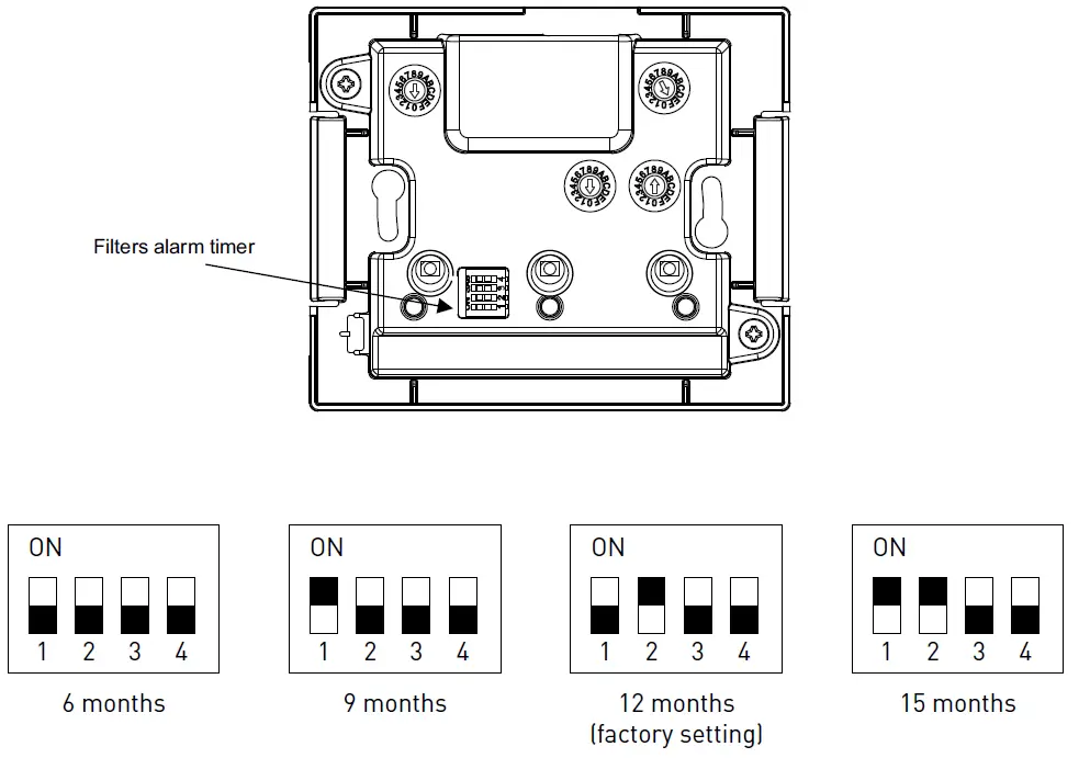
the black colour represents the switch position
Adjustment of the relative humidity %
The Altair has as a standard a humidity sensor in the extract air installed. This sensor allows to adjust the velocity in dependence of the relative humidity in the extract air. The upper limit of the relative humidity can be adjusted with the potentiometer as shown below (factory setting position A=84% rH).
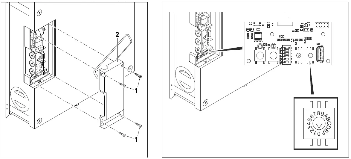
| Potentiometer position | Maximum relative humidity (%) |
| 0 | 64 |
| 1 | 66 |
| 2 | 68 |
| 3 | 70 |
| 4 | 72 |
| 5 | 74 |
| 6 | 76 |
| 7 | 78 |
| 8 | 80 |
| 9 | 82 |
| A | 84 |
| B | 86 |
| C | 88 |
| D | 90 |
| E | – |
| F | – |
Electronic board description
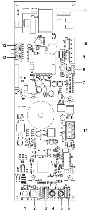
| 1 | without function |
| 2 | without function |
| 3 | DIP SWITCH 6: 1 (Default command) – 0 (SPCM) |
| 4 | without function |
| 5 | Set point humidity sensor. No function in case of connection of the SPCM-1 Module |
| 6 | USB connector (for software updates) |
| 7 | temperature sensor |
| 8 | humidity sensor |
| 9 | extract fan |
| 10 | supply fan |
| 11 | power supply motors (230V/50Hz) |
| 12 | without function |
| 13 | outgoing error signal |
| 14 | Command connection / SPCM-1 Communication module |
SPCM-1 COMMUNICATIONS MODULE: (optional)
The SPCM-1 communications board will allow you to connect the ALTAIR unit with the S&P IoT Platform: CONNECTAIR. To connect the SPCM-1 module to the ALTAIR you must first disconnect the control (14) and then connect the SPCM-1 with the cable supplied to the same terminal block (14). The communications module box can be attached to the ALTAIR for the Velcro type element. We recommend sticking it to one of the sheet metal braces to ensure its correct fixation. If it is not possible, two screws with their respective plugs are attached to be fi xed to the wall. To allow the output of ALTAIR to the Internet, you must first connect it to your router. The SPCM-1 communications module has a wired (ETHERNET) or wireless (WIFI) connection. Follow the instructions you will find in the module box.
Remote control adjustments – USER
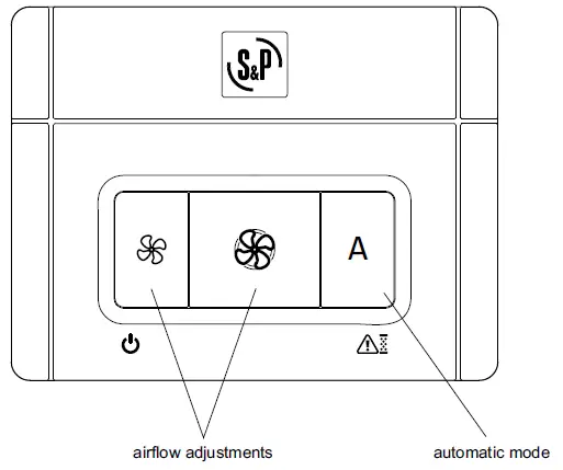
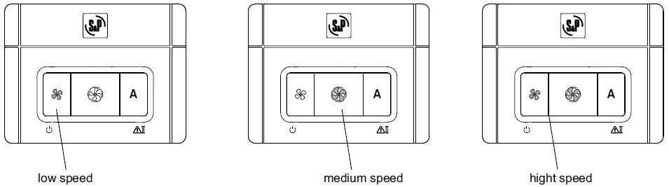
Speed adjustment
Pressing the “speed adjustment” buttons you can change the airfl ow. The LED of the active botton will light green (left fan symbol= decrease speed, right fan symbol=increase speed).
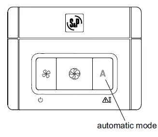
Automatic mode
Pressing the button “A” there can be activated the automatic mode. In the automatic mode works the unit proportional in dependence of the humidity measured in the extract airflow. The working range is between 45% humidity and the 80% relative humidity. The max. humidity can be adjusted as explained in “Adjustment of the relative humidity %”.
FILTER MAINTENANCE
We recommend a periodical maintenance of the filters (minimum 1x year). After the adjusted period de alarm will be activate. For changing the filter, please remove the plastic taps (1) put the filters (2) out and substitute them with new ones. After changing the filter put back the plastic taps.
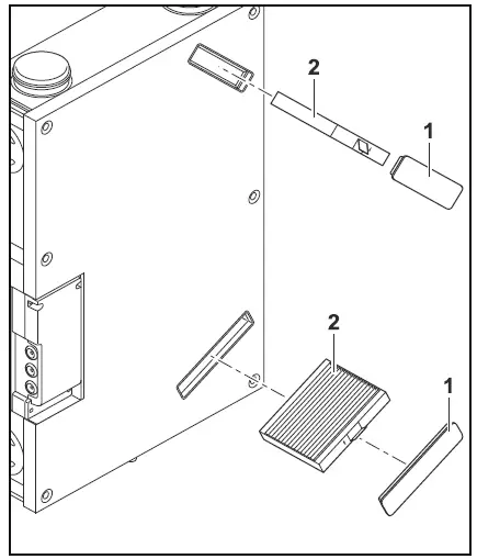
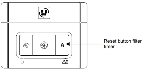
Everytime when fi lters are replaced the filter maintenance period has to be reseted pressing the button “A” during 5 seconds.
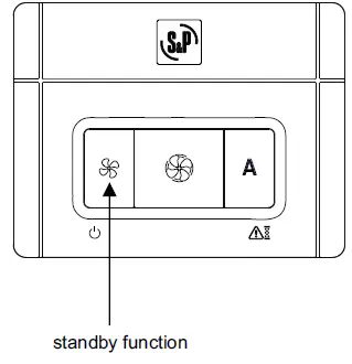
STANDBY FUNCTION
Push and hold the button![]() for 3 seconds, the unit will switch into the standby mode. During the standby mode the button (posar simbol ventilador) will be red illuminated (see drawing below). To switch the unit on push the button again.
for 3 seconds, the unit will switch into the standby mode. During the standby mode the button (posar simbol ventilador) will be red illuminated (see drawing below). To switch the unit on push the button again.
 ALARM INDEX
Through the LED located in the “A” button on the remote control it is possible to supervise the status of the unit. This LED will show the alarm in case of a failure or missfunction on the unit. Depending on the risk level of the generated alarm the unit will stop for safety reasons
| Priority | Alarm | LED | Action |
| 1 | Extract fan error | 1 red blink | unit stops |
| 2 | Supply fan error | 2 red blinks | unit stops |
| 3 | Supply air temperature <5ºC | 4 red blinks | unit stops. Every 2 hours the unit starts for 5 minutes to check if conditions allow normal operation. |
| 4 | Humidity sensor | 5 red blinks | normal operation |
| 5 | ODA sensor error (fresh air) | 7 red blinks | normal operation |
| 6 | SUP sensor error (supply air) | 8 red blinks | normal operation |
| 7 | ETA sensor error (extract air) | 9 red blinks | normal operation |
| 8 | EHA sensor error (exhaust air) | 10 red blinks | normal operation |
| 9 | Filter alarm | Red, continous | after 60 days the unit stops if filter is not changed an alarm reseted |
GENERAL DATA
| Height | 850 mm |
| Width | 550 mm |
| Depth | 170 mm |
| Connection | Ø 95 mm |
| Weight | 20 kg |
| Material | EPP body; front cover plate painted in white |
| Drain | ¾” (drainpipe) |
| Power supply | 230 V AC, 50 Hz |
| Maximum consumption | 55 W |
| Airflow | 120 m³/h |
| Radiated noise LwA | 52,2 dB(A) |
| Ambient temperature | from +10°C to +50°C |
| Exterior temperature | until -18°C |
| Extract temperature | from +10°C to +50°C |
| Speed control | according to the adjusted speed on the remote control |
| Fans | 2 units, forward curved with EC motor |
| Filters | supply G4 /extraction G4 |
| Thermal efficiency | 83% |
| Protection | IP21 |
PUTTING OUT OF SERVICE AND RECYCLING
EEC legislation and our consideration of future generations mean that we should always recycle materials where possible; please do not forget to deposit all packaging in the appropriate recycling bins. If your device is also labeled with this symbol, please take it to the nearest Waste Management Plant at the end of its servicable life.
ERP DATA
| Ecodesign Commission regulation (EU) N°1253/2014 of July 2014 Information requirements (Annex V) ALTAIR 120 H | ||
| a | Trade mark | S&P |
| b | Identifier | 5153811000 |
| c | SEC average climate (kWh/(m².an)) | -38,0 |
| SEC class | A | |
| SEC cold climate (kWh/(m².an)) | -75,1 | |
| SEC warm climate (kWh/(m².an)) | -14,2 | |
| d | Typology | RVU bidirectional |
| e | Type of drive | Variable speed drive |
| f | Type of HRC | Recuperative |
| g | Thermal efficiency (%) | 83 |
| h | Maximum flow rate (m³/h) | 120 |
| i | Electrical power input at maximum flow rate (W) | 55,0 |
| j | Sound power level (LWA) | 47 |
| k | Reference flow rate (m³/s) | 0,023 |
| l | Reference pressure difference (Pa) | 50,0 |
| m | SPI (W/m³/h) | 0,262 |
| n | Control factor | 0,85 |
| Control typology | Central demand | |
| o | Maximum internal leakage for BVU (%) | 2,9 |
| Maximum external leakage for BVU and UVU (%) | 2,9 | |
| p | Mixing rate for BVU without duct connection (%) | not applicable |
| q | Position of visual filter warning | Remote control |
| description of visual filter warning | Pilot light | |
| r | Instructions to install supply grilles | not applicable |
| Instructions to install exhaust grilles | not applicable | |
| s | Internet address | www.solerpalau.com |
| t | Airflow sensitivity to pressure variation | not applicable |
| u | Indoor/outdoor air tighness (m³/h) | not applicable |
| v | Annual electricity consumption – Average climat (kWh/a) | 282 |
| Annual electricity consumption – Warm climat (kWh/a) | 237 | |
| Annual electricity consumption – Cold climat (kWh/a) | 819 | |
| w | Annual heating saved – Average climat (kWh/a) | 4440 |
| Annual heating saved – Warm climat (kWh/a) | 2010 | |
| Annual heating saved – Cold climat (kWh/a) | 8690 | |
S&P SISTEMAS DE VENTILACIÓN, S.L.U. C. Llevant, 4 Polígono Industrial Llevant 08150 Parets del Vallès Barcelona – España Tel. +34 93 571 93 00 www.solerpalau.com


