![]()
CLIXX
MAGNETIC
TRACK SYSTEM
INSTALLATION INSTRUCTIONS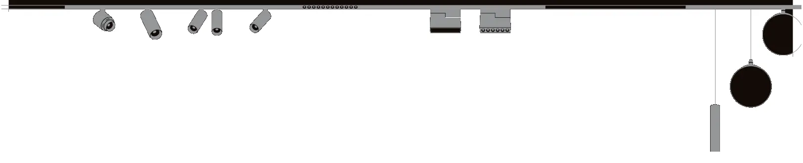
 |  |
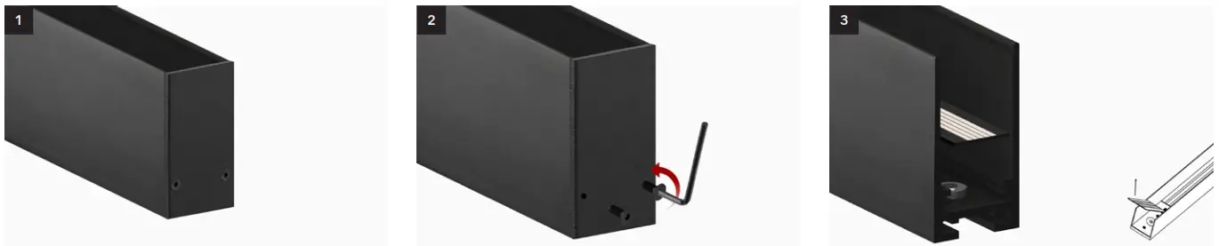
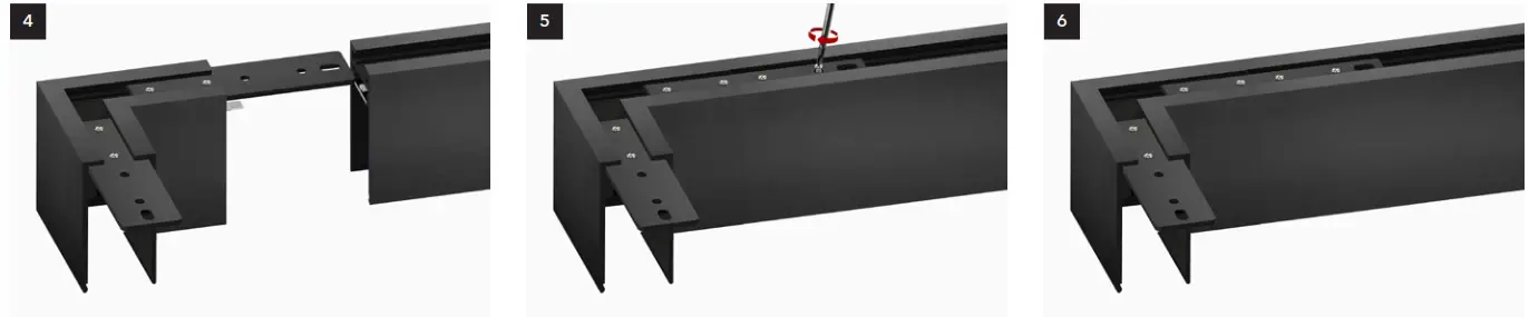
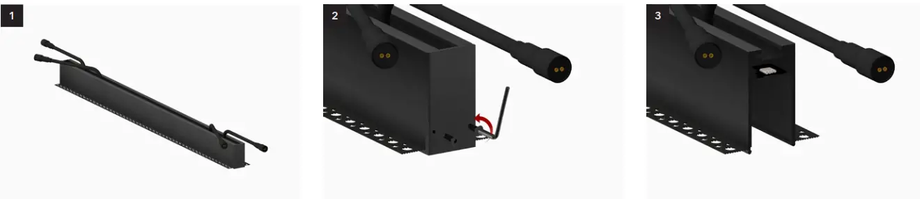
- CONNECTING TRACKS (SURFACE AND SUSPENDED INSTALLATION)

Place track on a flat clean surface. Remove the end caps with the included
hex key or screwdriver.Lift and remove the ‘decorative board*’ from
the magnet.
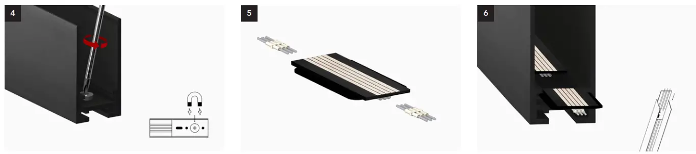
Remove the magnet that supports the decorative board with a screwdriver. Slide ‘pins’ into ‘powerplant’.
CLIXX SLIM: 2 x pin-2 for all dimming typesCLIXX regular: pin-3 for TRIAC, 2 x pin-2 for
1-10V and DALI.Insert the ‘powerplant’ into the track, and make sure the pins connect correctly. * The ‘decorative plate’ should only be removed when connecting both sides of the track. If only 1 side of the track is connected, choose the side without the plate, which can be connected directly with ‘pins’.

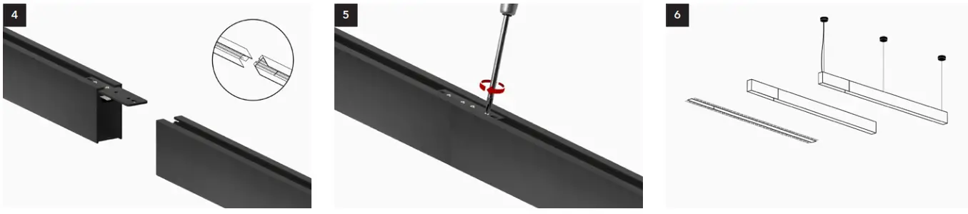
The track is now prepared for electrical
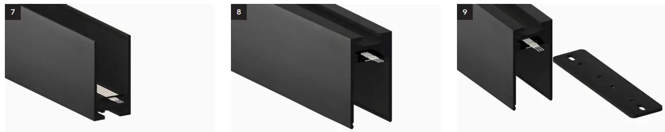
connection.Turn the track around. Slide the ‘track connector’ into the first track. 
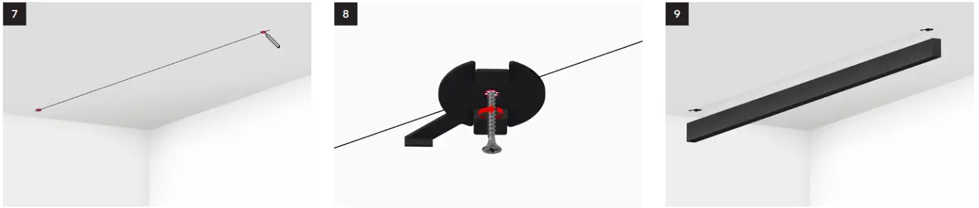
Tighten the included screws until the track
connector is fixed into place.Slide both the ‘track connector’ and ‘pins’ into
the second track, connecting tracks and
electrical circuit. Make sure the pins connect
with the terminal block.Tighten the included screws until the track
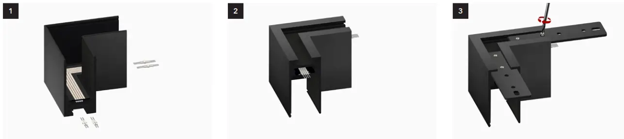
the connector is fixed into place - CONNECTING CORNERS (ALL INSTALLATIONS

Slide ‘pins’ into board.
CLIXX SLIM: 2 x pin-2 for all dimming types
CLIXX regular: pin-3 for TRIAC, 2 x pin-2 for
1-10V and DALI.Turn the track around. Slide the ‘track connectors’ into the corner
profile and tighten screws until fixed.
Slide both the ‘track connector’ and ‘pins’ into
the second track, connecting tracks and
electrical circuit. Make sure the ‘pins’ connect
with the terminal block.Tighten the included screws until the track
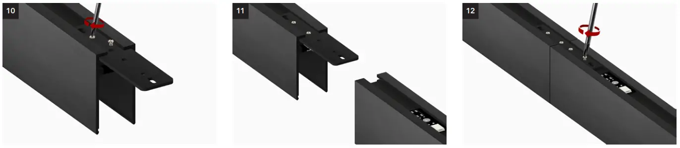
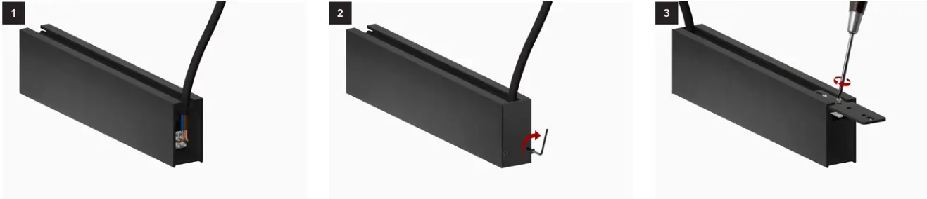
the connector is fixed into place.Repeat these steps for the other end(s). - CONNECTING TRACK DRIVER BOX (ALL INSTALLATIONS)

Connect the cable to the driver box (L/N/PE). The
driver box is available for all installation types.Attach the end cap to the driver box. Note that
the driver box is located at the start/end of the
track system or when connectable at both ends
in the middle.Slide the ‘track connector’ into the ‘driver box’
and tighten screws until fixed.
Slide both the ‘track connector’ and ‘pins’
into the track, connecting tracks and electrical
circuits. Make sure the ‘pins’ connect with the
terminal block in the track.Tighten the included screws until ‘track
connector’ is fixed into place.The driver box is available for all installation
types. Note that the recessed driver box is
different. There is also a driver box available
that can be connected at both ends and
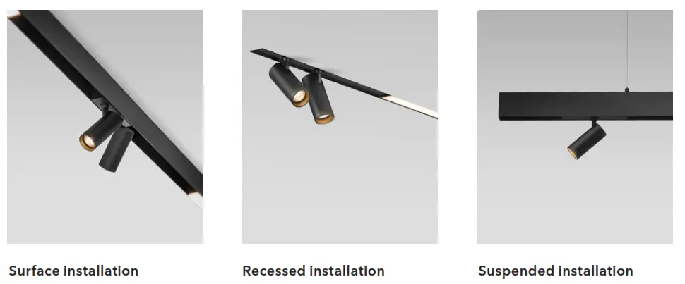
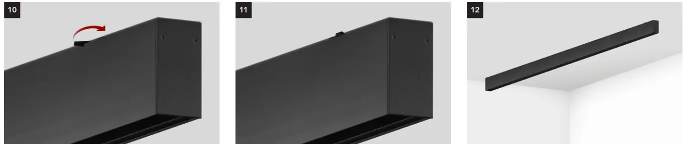
placed in the middle. - SURFACE INSTALLATION

Decide the position of the track and mark the position of
mounting clips. Detailed instructions on the next
page.Fix mounting clips to ceiling. Use plugs and
screws suitable for the specific ceiling type.
Make sure clips are aligned with the track.Place the track over the mounting clips, leaving
the levers exposed.
Turn the levers tight until the track is fixed into place.
Mounting of connected 2-meter tracks

Each 2-meter track requires 2 mounting clips. The dimensions given above are indicative. Corner profiles and driver boxes are supported by the track connectors and do not require any mounting clips. Make sure to use a clip near where the tracks are connected if you notice that the track connector alone does not give enough support.
Mounting of connected 1-meter tracks

A stand-alone 1-meter track requires 2 mounting clips. For connected tracks 1 mounting clip is sufficient. Corner profiles are supported by the track connectors and do not require any mounting clips. Corner profiles and driver boxes are supported by the track connectors and do not require any mounting clips. Make sure to use a clip near where the tracks are connected if you notice that the track connector alone does not give enough support.
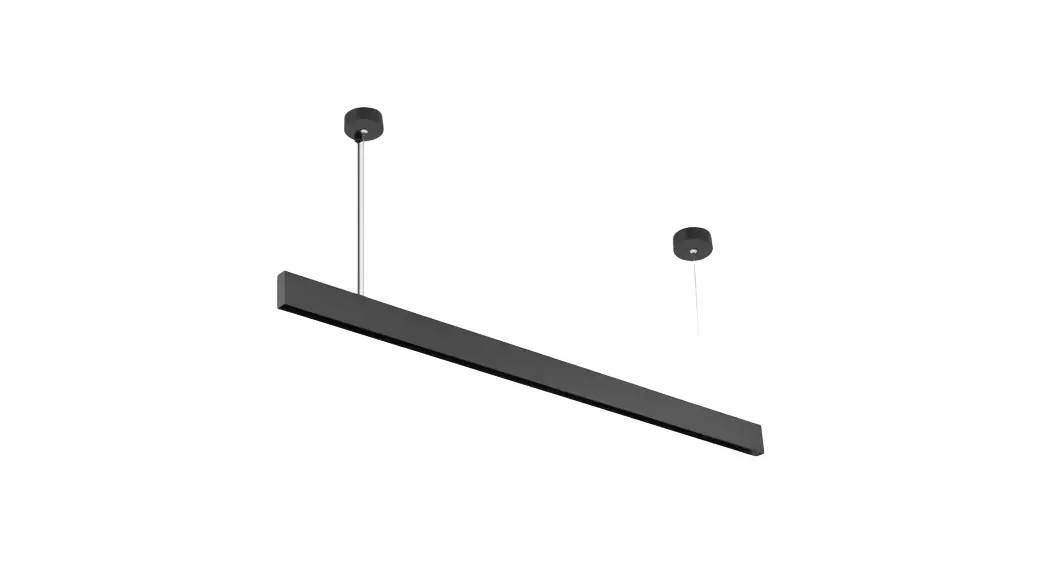
SUSPENDED INSTALLATION
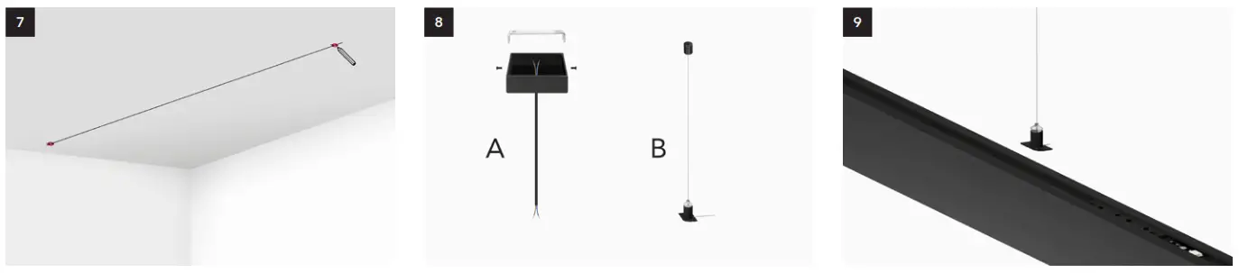 | ||
| Decide the position of the track and mark pendant clips. 2 for 1m and 2m track. | Attach the ceiling rose (A) over the central box and suspension brackets (B) to the ceiling. Use plugs and screws that are suitable for the specific ceiling type. | Place the tracks over the brackets. Connect the power cable on top of the track (between the sliders) or to the driver box or input terminal. (See page 15) |
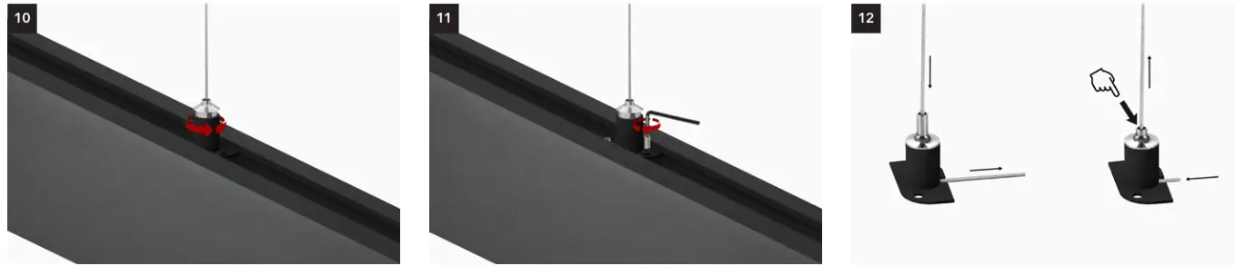 | ||
| Turn the suspension brackets until the straight side of the bracket is positioned under track exposing the screw holes. | Fix suspension brackets into place with included hex socket set. | – To shorten wire pull wire at the end – To extend the wire push the top and pull the wire up |
Mounting of connected 2-meter tracks

A stand-alone 2-meter track requires 2 mounting clips. For connected tracks 1 bracket is sufficient. The dimensions given above are indicative. Corner profiles and driver boxes are supported by the track connectors and do not require any brackets. Make sure to use brackets near where the tracks are connected if you notice that the track connector alone does not give enough support.
Montage van aangesloten 1 meter tracks

A stand-alone 1-meter track requires 2 suspension brackets. For connected tracks 1 bracket is sufficient. Corner profiles and driver boxes are supported by the track connectors and do not require any brackets. Make sure to use a bracket near where the tracks are connected if you notice that the track connector alone does not give enough support.
RECESSED INSTALLATION
 | ||
| Place tracks on a flat clean surface. | Remove the end caps with the included hex key. | No pins are required for the connection of the the electrical circuit between tracks, only use pins to connect corner profiles. |
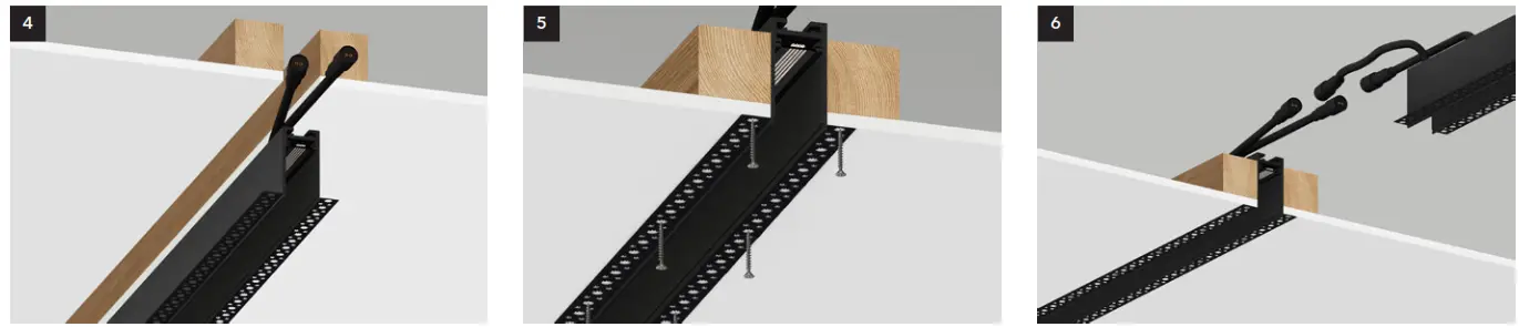 | ||
| Insert the track into the cut-out (ceiling/wall). | Use drywall screws (preventing rust) to fix the track in place. Wooden boards are recommended as support. Make sure screws do not protrude and do not distort the track. | Prepare the next track following the previous steps. |
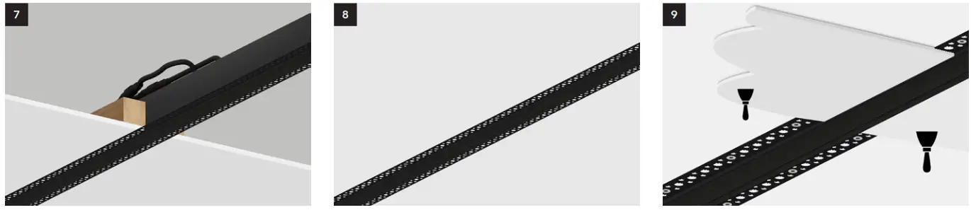 | ||
| Connect cable(s) on top. 1 cable for TRIAC and 0-10V, 2 cables for DALI. | Tracks are now connected and fixed to the ceiling. Always test the system with an LED module before applying the plaster! | Apply the plaster. |
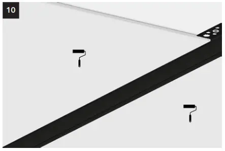 When the plaster is completely dry, apply paint.
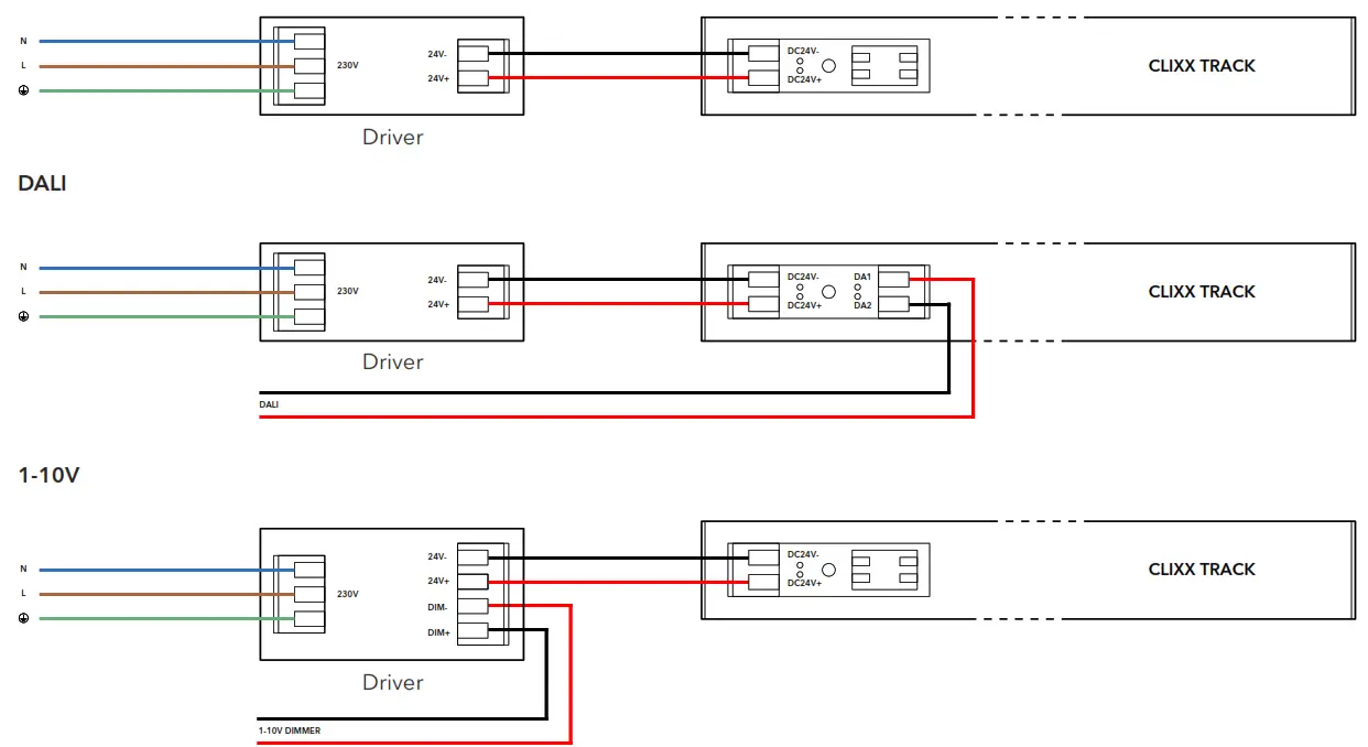
WIRING
TRIAC/ZIGBEE
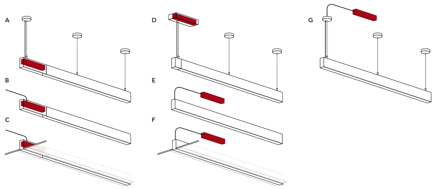
Situation A, B, C
The driver is located inside the driver’s box. Only in the case of DALI 2 wires should be guided over the driver box to the track. L, N, and PE are automatically connected to the track through the driver box.
Situation D
The driver is located inside the ceiling box. Wires are connected on top of the track or through the input terminal.
Situation E, F, G
The driver is located elsewhere. Make sure the driver is accessible at all times. Wires are connected on top of the track or through the input terminal.


