esse-ti 5HK-300 Kone Retrofit Kit
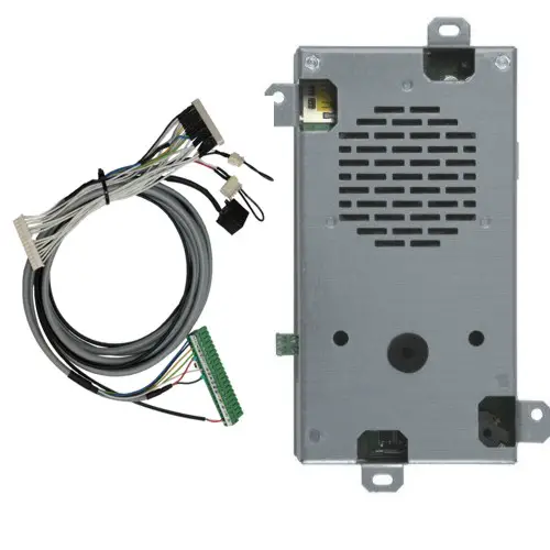
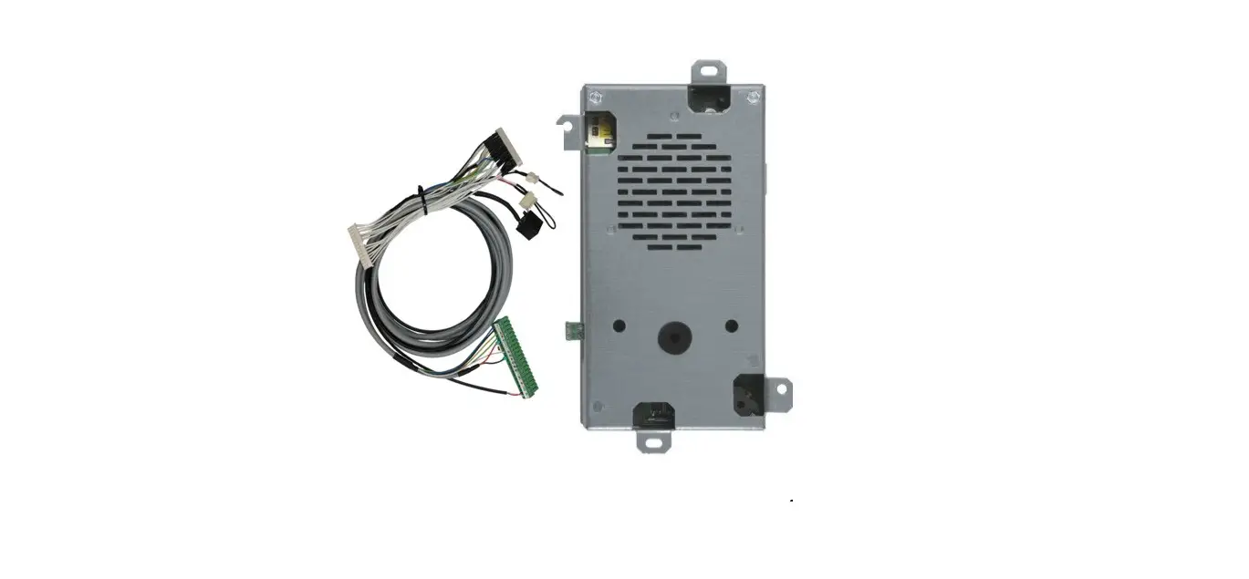
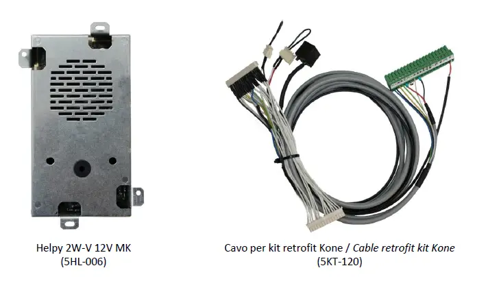
COMPONENTS
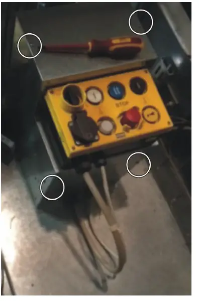
KRM INSTALLATION
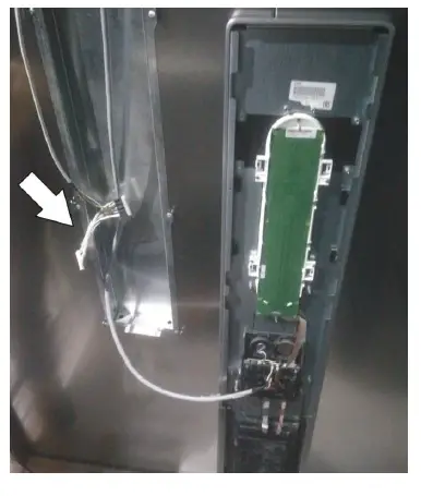
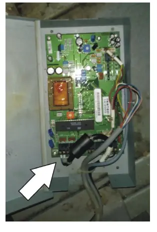
- Unscrew the 4 screws (shown in the picture) to remove the cover and gain access to the KRM.

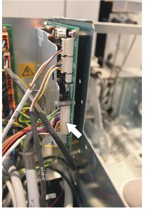
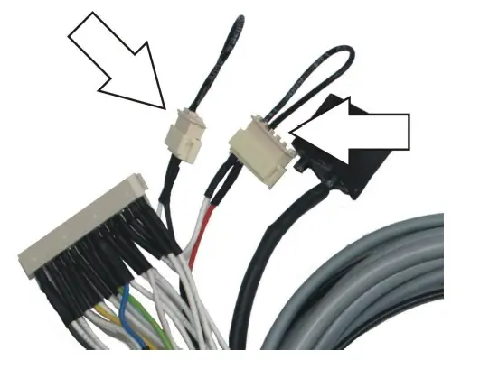
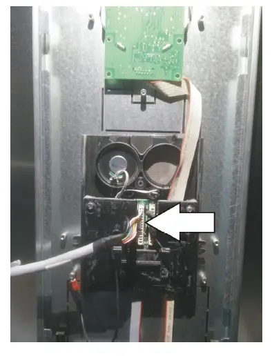
- Disconnect the XS1 and XS2 cables from the KRM board. KRM will turn off.

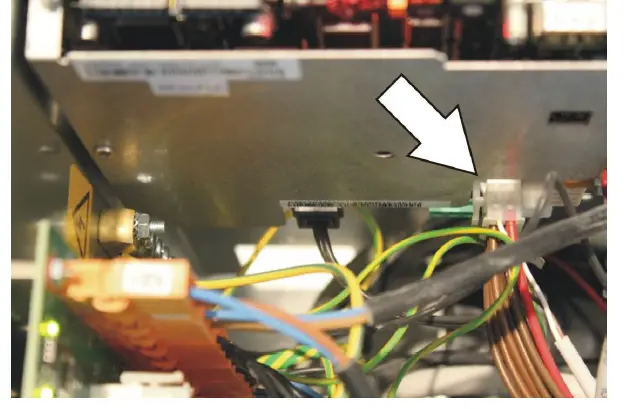
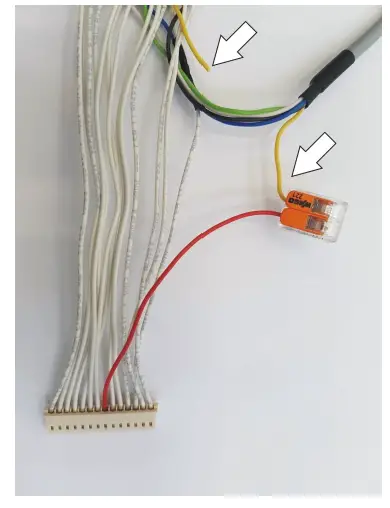
- Disconnect the 14-way X12 cable from the KRM board.

- Connect the X12 cable to the corresponding cable of the retrofit kit (5KT-120).
- Connect the other end of the retrofit kit cable to the KRM board (X12 connector).

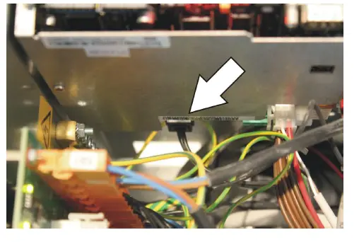
- Disconnect theRJ11 cable of the telephone line from the KRM board.
- Sometimes the telephone line is connected directly to the trailing cable (wires n° 15 and 16, often orange and white colors).
- Connect the telephone line to the RJ11 connector of the retrofit kit.

- Connect the terminal blocks of the retrofit kit to the Helpy 2W-V 12V MK.

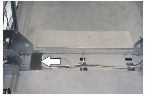
- Help 2W-V 12V MK can be installed on the top of the car. . Please make sure the microphone is placed in correspondence with a car hole and the audio quality is good.
- In any case Helpy 2W-V 12V MK can be installed facing upwards.

- Connect the XS1 and XS2 cables to the KRM board.
- Help 2W-V 12V MK will turn on (the red LED flashes briefly once every 3 seconds).
- If KRM starts an alarm, disconnect the XS1 and XS2 cables for few seconds.


Note: for basic programming see the table
- Disconnect the XS1 and XS2 cables from the KRM board. KRM will turn off.

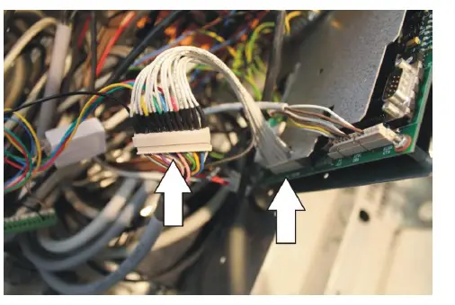
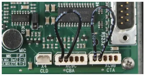
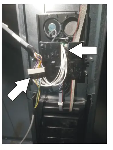
- Disconnect the XC9B and XC9C cables from the KRM board.

- Disconnect the two SPOX connector from the retrofit kit (5KT-120).

- Insert the two SPOX connectors into the XC9B and XC9C connectors on the KRM board.

- Connettere i cavi XS1 e XS2 alla scheda KRM. Helpy 2W-V 12V MK si accende (il LED rosso lampeggia una volta ogni 3 secondi).
- Connect the XS1 and XS2 cables to the KRM board. Helpy 2W-V 12V MK will turn on (the red LED flashes briefly once every 3 seconds)
Note: Helpy 2W-V 12V MK is factory programmed for normally closed car-top and car-bottom pushbuttons (4110).
KCEAPM INSTALLATION
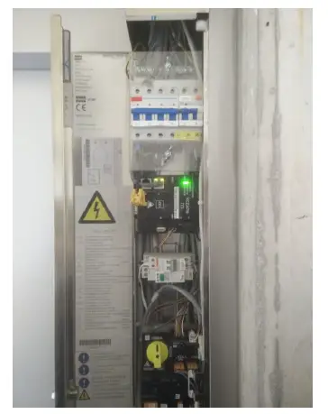
- Open the Maintenance Access Panel (MAP), integrated in a landing door or wall-mounted, to gain access to the KCEAPM.

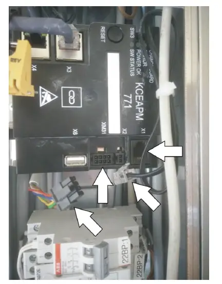
- Disconnect the XM31 (signals) and X1 (telephone line) cables from the KCEAPM. KCEAPM will turn off.

- Cut the yellow wire of the 5KT-120 retrofit kit cable (wire connected to pin n° 8 of the male Molex connector).

- Open the Car Operating Panel (COP).
- Lower the cable of the retrofit kit (5KT-120) from the car top.

- Disconnect the 14-way cable from the J2 connector.

- Connect the 14-way cable to the corresponding cable of the retrofit kit (5KT-120).
- Connect the other end of the retrofit kit cable to the J2 connector.

- Install Helpy 2W-V 12V MK on the top of the car.
Please make sure the microphone is placed in correspondence with a car hole and the audio quality is good. - In any case Helpy 2W-V 12V MK can be installed facing upwards.

- Helpy 2W-V 12V MK si accende (il LED rosso lampeggia una volta ogni 3 secondi).

Connecting the telephone line
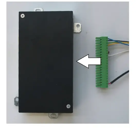
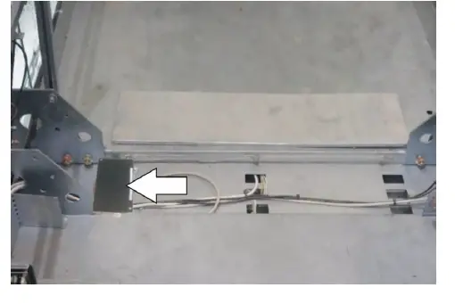
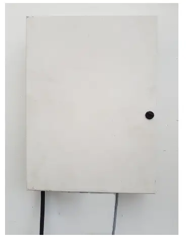
- Open the Base Unit Module installed at the top of the lift shaft.
- Disconnect the telephone line from the Base Unit Module.
- Disconnect the 4-way cable from the Base Unit Module.
- Connect the 2 wires of the telephone line to any of the 2 wires in the 4-way cable

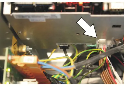
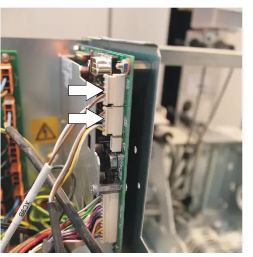
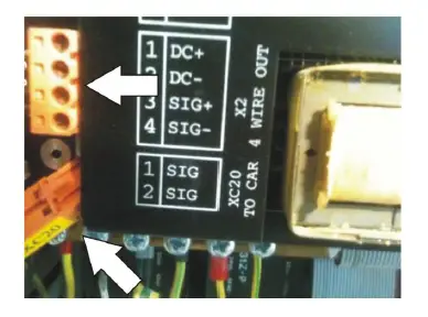
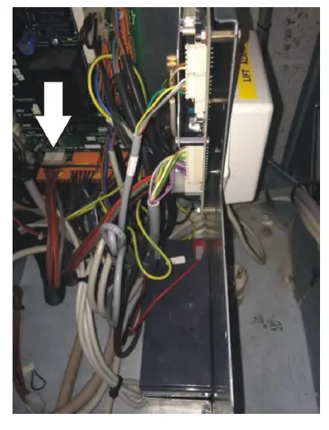
- Disconnect from the LCEKNX KoneXion car interface (in the middle of the controller, in the lift shaft) the 4-way cable that comes from the Base Unit Module .
- Disconnect the XC20 connector.
- Connect the 2 wires of the 4-way cable used for the telephone line to the XC20 cable (trailing cable).

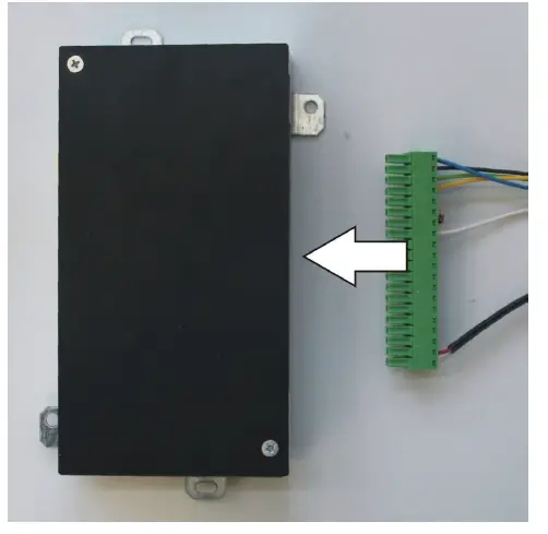
- Open the Car Unit in Metal Box installed on the top of the car.
- Disconnect the brown and blue wires from the Car Unit.
- Connect the brown and blue wires to the LTI terminals of Helpy 2W-V 12V MK.

Connecting the pushbutton
- Disconnect the white connector XB18 (10-way cable) from the box installed on the top of the car.
- Cut the wire marked with number 5.
- Connect both ends of wire 5 to a side of a 12 V relay coil.
- Connect the other side of the relay coil to earth/ground.
- Reconnect the connector XB18

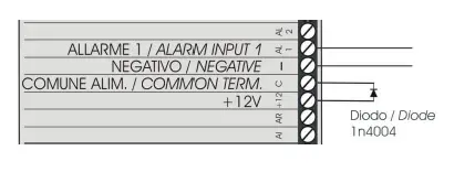
- Connect the normally open contacts of the relay to AL1 and — terminals of Helpy 2W-V 12V MK.
- Connect the diode between +12 and C terminals.

Note: for basic programming see the table
BASIC PROGRAMMING
| Access to programming | *0# |
| 1st telephone number for emergency call | 210112<telephone number># |
| 2nd telephone number for emergency call | 210212<telephone number># |
| 3rd telephone number for emergency call | 210312<telephone number># |
| telephone number for periodic test call (CLI mode) | 210434<telephone number># |
| Record identification message | 7101<registrare/record> |
| Listen to identification message | 7201<listen> |
| Emergency call button delay | 42X (X=3-9 seconds) |
| Emergency input AL1 normally closed/open | 4100 normally closed
|
| Exiting the programming | *0# |


