![]()
![]()
Schindler Retrofit Kit
Instruction Manual
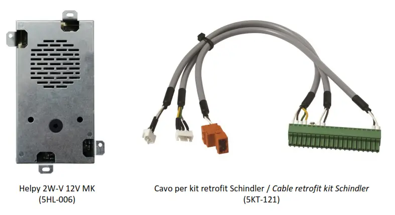
COMPONENTS
ETMA INSTALLATION
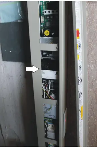
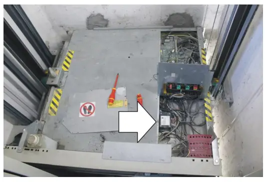
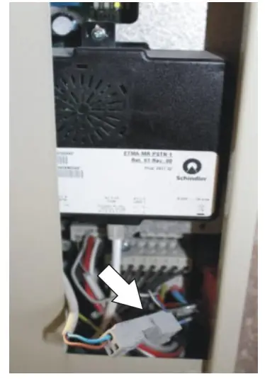
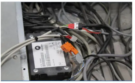
Open the panel located on the highest landing floor. ETMA-MR is placed at the center of the panel.
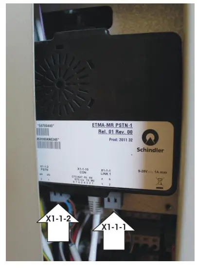
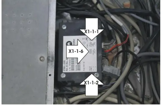
Disconnect the X1-1-1 and X1-1-2 cables from ETMA-MR (X1-1-1 connects ETMA-MR to the ETMA-CAR located on the car roof or to the board located in the COP; 1-1-2 connects ETMA-MR to the telephone line).
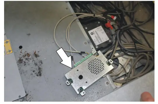
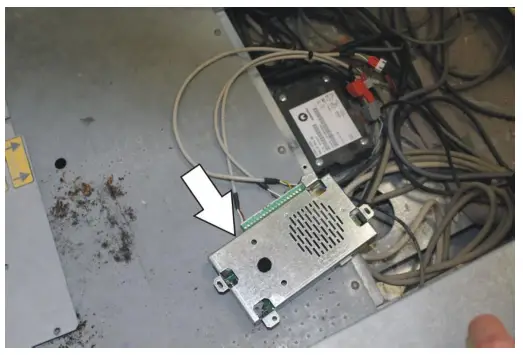
On the car roof, open the panel located under the service buttons. ETMA-CAR is highlighted by the white arrow.
Disconnect the cables X1-1-2: link to ETMA-MR X1-1-6: power supply and LEDs X1-1-1: pushbutton normally closed.
if the ETMA-CAR is not located on the car roof
Open the Car Operating Panel (COP) and lower the cable of the retrofit kit (5KT-121) from the car top.
Disconnect the cables: CAR. ALARM: pushbutton normally closed CAR. POWER: power supply and LEDs LINK: link to ETMA-MR.
Open the Car Operating Panel (COP) and lower the cable of the retrofit kit (5KT-121) from the car top.
Disconnect the cables: CAR. ALARM: pushbutton normally closed CAR. POWER: power supply and LEDs LINK: link to ETMA-MR.
Connect the cables to the corresponding cables of the retrofit kit (5KT-121), as shown in the picture.
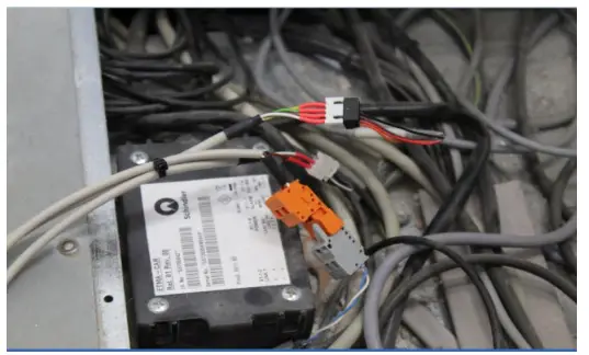
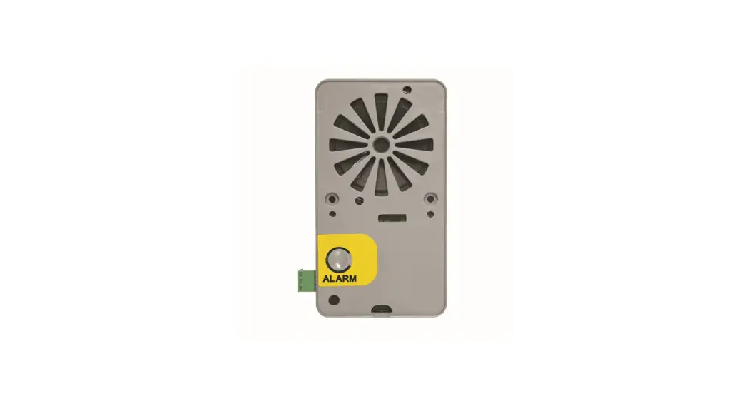
Connect a telephone to the terminal blocks of the retrofit kit. Connect the terminal blocks of the retrofit kit to the Helpy 2W-V 12V MK. . Helpy 2W-V 12V MK will turn on. If an alarm starts lift the telephone handset and dial *0# (to reset the alarm), *0# (to enter programming mode) and 4101 (to set the AL1 input as normally closed). . Helpy 2W-V 12V MK can be installed in place of the ETMACAR. Please make sure the microphone is placed in correspondence with a car hole and the audio quality is good. . In any case Helpy 2W-V 12V MK can be installed facing upwards.
Connect the X1-1-1 and X1-1-2 cables, disconnected from the ETMA-RM, together.
 Note: for basic programming see the table on the last page.
INSTALLAZIONE TAM
On the car roof, open the panel located under the service buttons. TAM2 is highlighted by the white arrow.
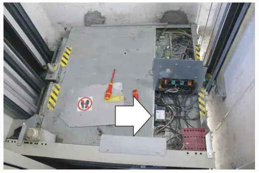
Disconnect the cables X1-1-2: telephone line X1-1-6: power supply and LEDs X1-1-1: pushbutton normally closed.
 Connect the cables to the corresponding cables of the retrofit kit (5KT-121), as shown in the picture.
Connect a telephone to the terminal blocks of the retrofit kit. Connect the terminal blocks of the retrofit kit to the Helpy 2W-V 12V MK. . Helpy 2W-V 12V MK will turn on. If Helpy 2W-V 12V MK doesn’t turn on, you should use the universal power supply ST-Power 12V (5HA-005), see the next page. . If an alarm starts lift the telephone handset and dial *0# (to reset the alarm), *0# (to enter programming mode) and 4101 (to set the AL1 input as normally closed). . Helpy 2W-V 12V MK can be installed in place of the TAM2. . Please make sure the microphone is placed in correspondence with a car hole and the audio quality is good. . In any case Helpy 2W-V 12V MK can be installed facing upwards.
 Note: for basic programming see the table on the last page.
UNIVERSAL POWER SUPPLY ST-POWER 12V
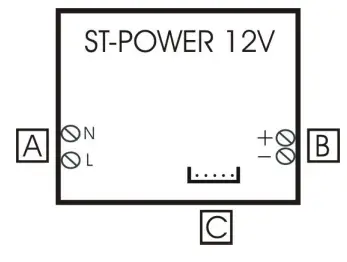
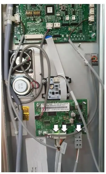
- Connect the universal power supply ST-Power 12V (5HA-005) to the Helpy 2W-V MK by means of the 12 Vdc terminal (B in the figure).
- Connect a 12 V 1,3 Ah battery to the universal power supply ST-Power 12V by means of the two faston cables (it is necessary to open the cover by removing the fixing screw).
- Connect the 100-240 Vac mains voltage cable by means of N and L terminals (A in the figure).
BASIC PROGRAMMING
| Access to programming | *0# |
| 1s telephone number for emergency call | 210112<numero di telefono/telephone number># |
| 2′ telephone number for emergency call | 210212<n umero di telefono/telephone number># |
| 3rd telephone number for emergency call | 210312<numero di telefono/telephone number># |
| the telephone number for periodic test call (CLI mode) | 210434<numero di telefono/te/ephone number># |
| Record identification message | 7101<registrare/record><riagganciare/hang up> |
| Listen to the identification message | 7201<ascoltare/listen> |
| Emergency call button delay | 42X (X=3-9 secondi/seconds) |
| Emergency input AU normally closed/open | 4111 normalmente aperto/normally open |
| Exiting the programming | *0# |
![]() Esse-ti S.r.l. Via G.
Esse-ti S.r.l. Via G.
Capodaglio, 9
62019Recanati (MC) — ITALY
Tel. +39 071 7506066
Fax +39 071 7506057
www.esse-ti.it
[email protected]


