KEMPPI Flexlite GC Lightweight Entry-Level MIG Welding Gun User Manual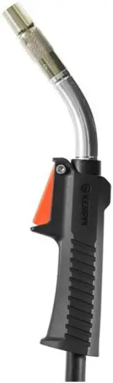
GENERAL
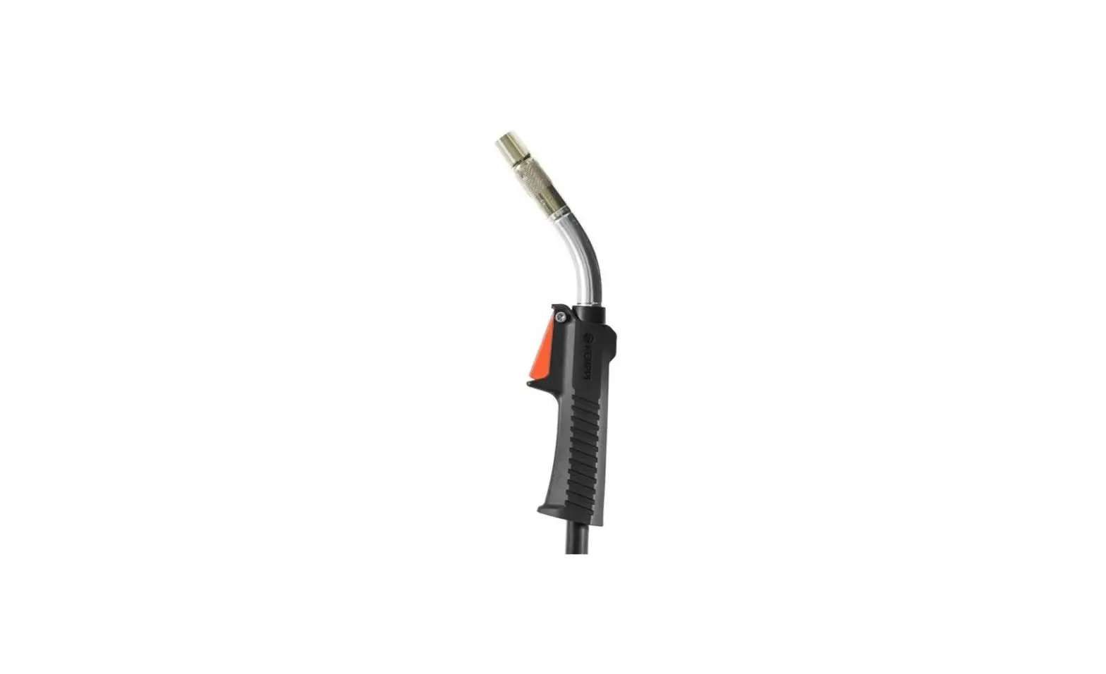
These instructions describe the use of Kemppi’s Flexlite GC MIG welding guns. Flexlite GC welding guns are designed for manual welding.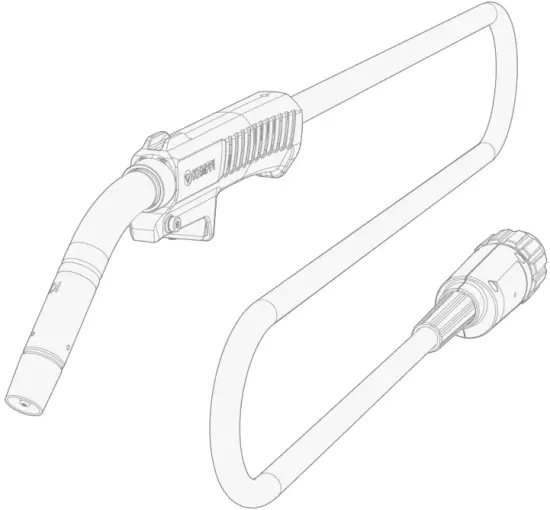
| Flexlite GC models With Euro connector: | Fixed connection (with MinarcMig Evo): |
| GC253G | GC223GMM |
| GC323G |
Inmodelnames: G = Gas-cooled, MM = MinarcMig.
Important notes
Read the instructions through carefully. For your own safety, and that of your working environment, pay particular attention to the safety instructions delivered with the equipment.
Items in the manual that require particular attention in order to minimize damage and harm are indicated with the below symbols. Read these sections carefully and follow their instructions.
 Note: Gives the user a useful piece of information.
 Caution: Describes a situation that may result in damage to the equipment or system.
- Warning: Describes a potentially dangerous situation. If not avoided, it will result in personal damage or fatal injury.
DISCLAIMER
While every effort has been made to ensure that the information contained in this guide is accurate and complete, no liability can be accepted for any errors or omissions. Kemppi reserves the right to change the specification of the product described at any time without prior notice. Do not copy, record, reproduce or transmit the contents of this guide without prior permission from Kemppi.
ABOUT EQUIPMENT
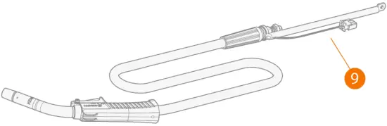
The Flexlite GC MIG welding gun equipment consists of: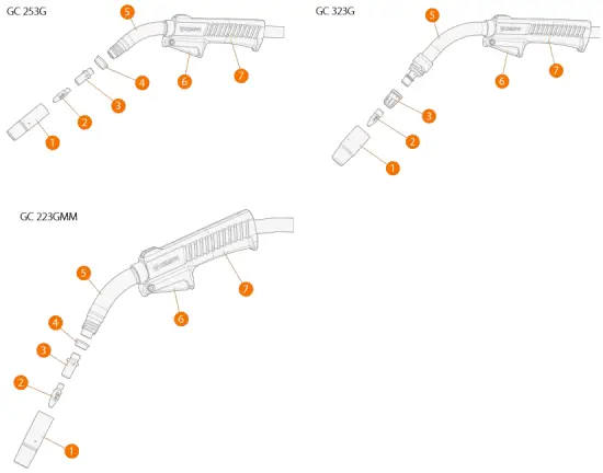
- Gas nozzle
- Contact tip
- Contact tip adapter/gas diffuser
- Insulating ring
- Gun neck
- Trigger switch
- Handle
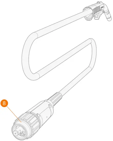
- Flexlite GC 253G and GC 323G: Gun connector (Euro)

- Flexlite GC 223GMM: MinarcMig Evo gun connectors.Flexlite GC 223GMM welding gun is delivered factory-installed with MinarcMig Evo welding equipment.

- Additional grip handle

EQUIPMENT IDENTIFICATION
Quick Response (QR) code
Device-related information or a web link to such information may be found in the form of a QR code on the device. The code can be read, for example, with a mobile device camera and a QR code application.
INSTALLATION
![]() Ensure that the welding equipment is not connected to the mains and that the welding gun is not connected to the welding machine until the installation is complete.
Ensure that the welding equipment is not connected to the mains and that the welding gun is not connected to the welding machine until the installation is complete.![]() Protect the equipment from rain and direct sunshine.
Protect the equipment from rain and direct sunshine.
Before installation and use
Make sure that you select appropriate welding gun contact tip and wire liner for the filler wire used. Refer also to “Technical data: Flexlite GC” on page 22 and “Component selection”.
Ensure compliance with your local and national safety requirements regarding the installation and use of high voltage units.
Check the contents of the packages and make sure the parts are not damaged.
Assembling gun
For the correct components, refer to “Component selection”.
Tools needed: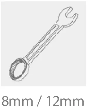
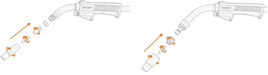
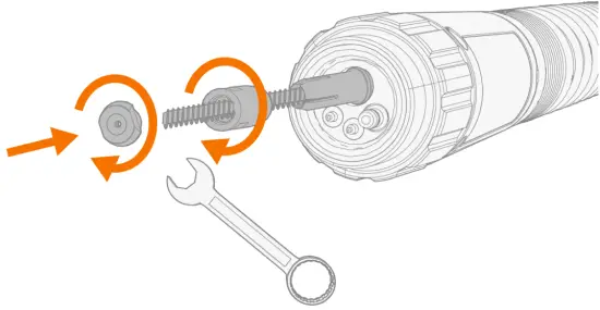
- Flexlite GC 253G and GC 223 GMM: Insert the isolation ring in place.
- Attach the contact tip adapter and tighten it firmly in place. With Flexlite GC 253G and GC 223 GMM, use a spanner for tightening.It is important to tighten the adapter properly to enable a tight connection of the contact tip to the gun.
- Attach the contact tip and secure it with a spanner.
- Attach the gas nozzle and hand-tighten it firmly in place.

Connecting gun
This section does not apply to Flexlite GC 223GMM welding gun. It comes factory-installed with MinarcMig Evo welding equipment.
![]() Hand-tighten the gun connectors. Loose connectors may overheat, create contact disturbances, mechanical damage and gas leakage.
Hand-tighten the gun connectors. Loose connectors may overheat, create contact disturbances, mechanical damage and gas leakage.
![]() For connecting the gun (and applicable extension parts), refer also to your welding equipment’s instructions.
For connecting the gun (and applicable extension parts), refer also to your welding equipment’s instructions.
![]() If not already preinstalled, the wire liner must be installed before connecting the gun. Refer to “Installing and replacing wire liner” on the next page for instructions.
If not already preinstalled, the wire liner must be installed before connecting the gun. Refer to “Installing and replacing wire liner” on the next page for instructions.
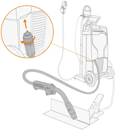
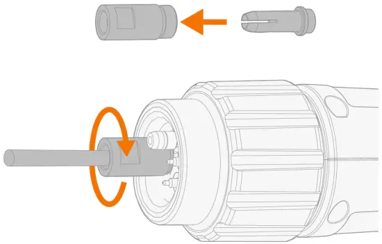
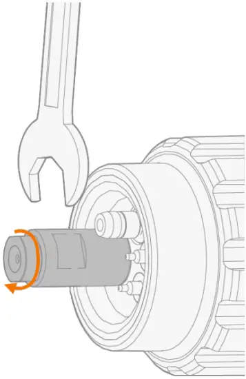
- Connect the gun to your welding equipment.

- Secure the connector in place by turning the collar clockwise.
Installing and replacing wire liner
This replacement instruction does not apply to Flexlite GC 223GMM welding gun. For replacing the wire liner in Flexlite GC 223GMM welding gun, refer to MinarcMig Evo operating manual.
The Flexlite GC MIG welding gun cable packs are delivered with the wire liner preinstalled. Refer to this section when the wire liner needs to be replaced.
The wire liner is a consumable part, which needs to be changed if worn and when the filler wire material changes.
![]() If you change the filler wire to a different diameter or material, change also the feed rolls accordingly.
If you change the filler wire to a different diameter or material, change also the feed rolls accordingly.
![]() Both steel spiral wire liner and DL Chili wire liner can be used.
Both steel spiral wire liner and DL Chili wire liner can be used.
![]() The filler wire must be removed before the wire liner replacement.
The filler wire must be removed before the wire liner replacement.
Tools needed: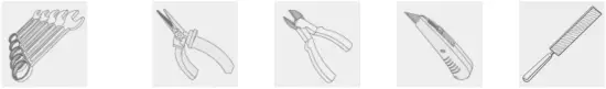
Removing and inserting wire liner
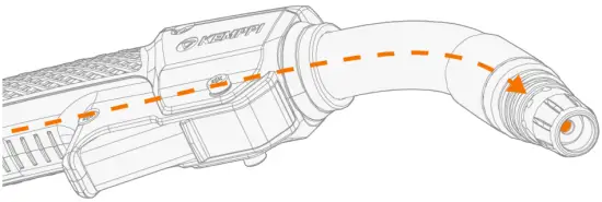
- Straighten the welding gun cable.
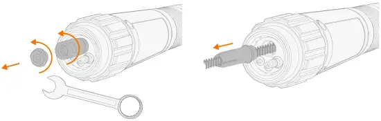
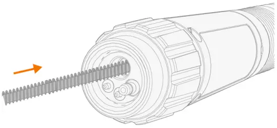
- At the wire feeder end of the cable, remove the wire liner’s end cap, sleeve nut and retainer cone.

- If you are replacing an existing wire liner with a new one, remove the old wire liner from the cable hose.If you still plan to use the same wire liner later, make sure not to damage the wire liner at this stage.

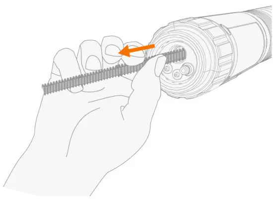
- Feed the new wire liner into the cable hose until it stops at the gun neck end.
Ensure that the contact tip adapter and contact tip are in place at this stage. Otherwise, depending on the welding gun model, the wire liner will go through without stopping. (With GC 323G only contact tip adapter is required at this stage.)
To ensure that the wire liner is in the correct position, temporarily remove the welding gun contact tip. For more information on the contact tip, refer to “About equipment” and “Assembling gun”.
Steel spiral: Cutting wire liner and installing sleeve assembly
- Cut off the fixed sleeve nut at the end of the wire liner.

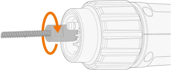
- Insert the sleeve nut (delivered with the wire liner) without end cap and retainer cone on the wire liner and tighten it temporarily in place for measure.

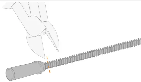
- Cut the wire liner flush with the sleeve nut end.
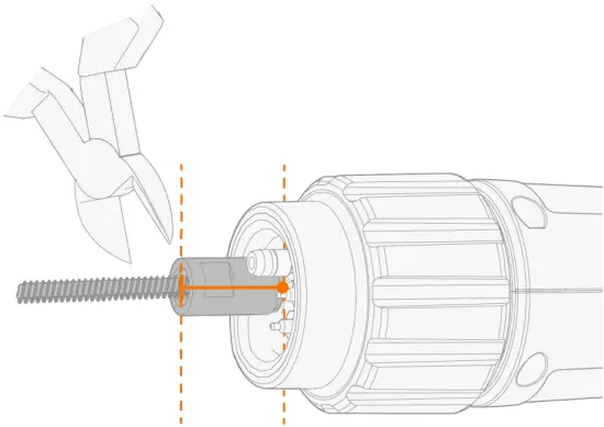
 Cut the excess of the steel spiral liner with side cutting pliers.
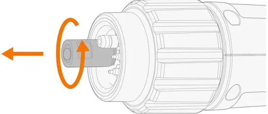
 - Remove the sleeve nut.

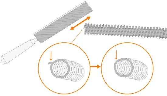
- Steel spiral wire liner only: File the end of the liner.Don’t leave any rough edges that could potentially damage the filler wire.
- Insert first the retainer cone and then the sleeve and end cap on the wire liner. Tighten the sleeve and end cap in place.

DL Chili: Cutting wire liner and installing sleeve assembly.
- Insert the sleeve nut (delivered with the wire liner) with the retainer cone on the wire liner and tighten it in place.

- Cut the wire liner flush with the sleeve nut end.
 Cut the excess of the Chili liner with a carpet knife.
 - Insert first the retainer cone and then the sleeve and end cap on the wire liner. Tighten the sleeve and end cap in place.


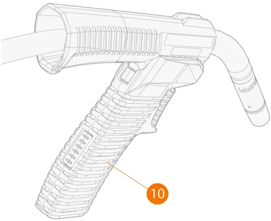
Installing and removing grip handle (optional)
The additional grip handle is available for all Flexlite GC MIG welding guns.
- Keeping the bottom of the grip handle pointing forward, fit the inside grooves of the grip handle over the screws on the gun.
- Pull the handle backward to lock it in position.

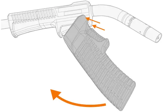
To remove the grip handle, press the unlock button in the grip handle rear.
OPERATION
Before using the equipment, ensure that all the necessary installation actions have been completed according to your equipment setup and instructions.
![]() Welding is forbidden in places where there is an immediate fire or explosion hazard!
Welding is forbidden in places where there is an immediate fire or explosion hazard!
![]() Welding fumes may cause injury. Take care to ensure sufficient ventilation during welding and wear respiratory protection!
Welding fumes may cause injury. Take care to ensure sufficient ventilation during welding and wear respiratory protection!
![]() Always check before use that interconnecting cable, shielding gas hose, earth return lead/clamp and mains cable are in serviceable condition. Ensure that the connectors are correctly fastened. Loose connectors can impair welding performance and damage connectors.
Always check before use that interconnecting cable, shielding gas hose, earth return lead/clamp and mains cable are in serviceable condition. Ensure that the connectors are correctly fastened. Loose connectors can impair welding performance and damage connectors.
![]() The exact function of the gun and trigger may vary depending on your welding machine settings (e.g. 2T or 4T trigger logic).
The exact function of the gun and trigger may vary depending on your welding machine settings (e.g. 2T or 4T trigger logic).
To start welding, press the trigger switch.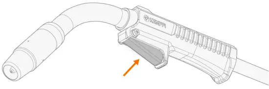
For the correct components, refer to “Component selection”.
MAINTENANCE
When planning routine maintenance, consider the operating frequency of the welding equipment and the working environment.
Correct operation of the welding equipment and regular maintenance helps you avoid unnecessary downtime and equipment failure. Mainly due to the high temperatures, MIG guns require regular checks and maintenance. Periodically, check the cables set for damage and ensure connections are tightened correctly.
Daily maintenance
![]() Disconnect the power source from the mains power supply before handling electrical cables.
Disconnect the power source from the mains power supply before handling electrical cables.
- Check regularly that all the components are tightly fastened.
- Check that the current transfer surface on the Kemppi gun adapter is clean and unscratched, and the connector pins are straight and undamaged.
- Check the cable for damage.
- Check the O-rings in the welding gun gas connector for wear and damage.
- Clean dust from the liner with pressurized air every time you change the wire spool, or every day during heavy use.
- Check and remove any spatter build-up from the nozzle.
- Check that the rotating neck has not been loosened by turning the neck (unintentionally). The rotating neck is fixed on threads and, if turned enough, it comes off.
- Check also that the rotating neck has not been over-tightened. If tightened to the last thread, rotation is limited.
- When not using the gun, keep it in the welding gun holder on the wire feeder.
For repairs, contact your Kemppi dealer.
Periodic maintenance
![]() Only qualified service personnel are allowed to carry out periodic maintenance.
Only qualified service personnel are allowed to carry out periodic maintenance.
Check the electrical connectors of the unit at least every six months. Clean oxidized parts and tighten loose connectors.
![]() Use the correct tension torque when fastening loose parts.
Use the correct tension torque when fastening loose parts.
![]() Do not use pressure washing devices.
Do not use pressure washing devices.
Service workshops
Kemppi Service Workshops complete the welding system maintenance according to the Kemppi service agreement. The main aspects in the service workshop maintenance procedure are:
- Cleanup of the machine
- Maintenance of the welding tools
- Checkup of the connectors and switches
- Checkup of all electric connections
- Checkup of the power source mains cable and plug
- Repair of defective parts and replacement of defective components
- Maintenance test
- Test and calibration of operation and performance values when needed. Find your closest service workshop at Kemppi website.
Troubleshooting
![]() The problems and the possible causes listed are not definitive, but suggest some typical situations that may turn up during normal use of the welding system. For further information and assistance, contact your nearest Kemppi service workshop.
The problems and the possible causes listed are not definitive, but suggest some typical situations that may turn up during normal use of the welding system. For further information and assistance, contact your nearest Kemppi service workshop.
General:
The welding system does not power up
- Check that the mains cable is plugged in properly.
- Check that the mains switch of the power source is at the ON position.
- Check that the mains power distribution is on.
- Check the mains fuse and/or the circuit breaker.
- Check that the earth return cable is connected.
The welding system stops working
- The gun may have overheated. Wait for it to cool down.
- Check that none of the cables is loose.
- The wire feeder may have overheated. Wait for it to cool down and see that the welding current cable is properly attached.
- The power source may have overheated. Wait for it to cool down and see that the cooling fans work properly and the air flow is unobstructed.
Wire feeder:
The filler wire on the spool unravels
- Check that the spool locking cover is closed. The wire feeder does not feed the filler wire
- Check that the filler wire has not run out.
- Check that the filler wire is properly routed through the feed rolls to the wire liner.
- Check that the pressure handle is properly closed.
- Check that the feed roll pressure is adjusted correctly for the filler wire.
- Blow compressed air through the wire liner to check that it is not blocked.
Welding gun:
The wire burns into the contact tip
- Make sure the size and type of the current tip and liner are suitable for the filler wire.
- Make sure the wire liner is clean.
- Make sure the wire liner does not make any steep loops.
- Check the motor current level. If the current is too high, there may be problems in the wire liner.
- Check the tightness of the feeding rolls. Too tight feeding rolls may affect soft filler wires, such as aluminium and flux-cored wires.
The gun overheats
- Make sure the gun’s neck is correctly connected to the handle. >> Check that the rotating neck is not loose or over-tightened by turning the rotating neck.
- Make sure that the contact tip adapter is properly tightened and the contact tip properly attached to it.
- Make sure that the welding parameters are within the range of the welding gun and the neck.
The gun neck overheats
- Make sure you are using original Kemppi consumable and spare parts. Incorrect spare part materials may cause the overheating of the neck.
The welding gun connector overheats
- Make sure the connector is properly connected to the wire feeder.
- Make sure the current transfer surface and the connector pins of the gun connector are clean and undamaged.
The gun vibrates too much during welding
- Check the tightness of the contact tip adapter and contact tip.
- Check the motor current.
- Check the wire liner (e.g. for dirt and to ensure that the wire liner has been cut properly).
- Check the filler wire. It must be straight and start coiling when it comes out from the contact tip. If not, check the tightness of the feeding rolls.
- Check the filler wire batch for any quality issues with the wire.
Weld quality:
Dirty and/or poor weld quality
- Check that the shielding gas has not run out.
- Check that the shielding gas flow is unobstructed.
- Check that the gas type is correct for the application.
- Check the polarity of the gun/electrode.
- Check that the welding procedure is correct for the application.
Varying welding performance
- Check that the wire feed mechanism is adjusted properly.
- Blow compressed air through the wire liner to check that it is not blocked.
- Check that the wire liner is correct for the selected wire size and type.
- Check the welding gun contact tip’s size, type and wear.
- Check that the welding gun is not overheating.
- Check that the earth return clamp is properly attached to a clean surface of the workpiece.
High spatter volume
- Check the welding parameter values and welding procedure.
- Check the gas type and flow.
- Check the polarity of the gun/electrode.
- Check that the filler wire is correct for the current application.
Disposal of machine
Do not dispose of any electrical equipment with normal waste!
In observance of WEEE Directive 2012/19/EU on waste of electrical and electronic equipment and European Directive 2011/65/EU on the restriction of the use of certain hazardous substances in electrical and electronic equipment, and their implementation in accordance with national law, electrical equipment that has reached the end of its life must be collected separately and taken to an appropriate environmentally responsible recycling facility. The owner of the equipment is obliged to deliver a decommissioned unit to a regional collection center, as per the instructions of local authorities or a Kemppi representative. By applying these European Directives you improve the environment and human health.
TECHNICAL DATA
- “Technical data: Flexlite GC”.
- For component selection, refer to “Component selection”.
- For ordering codes, refer to “Ordering codes”.
Technical data: Flexlite GC
| Flexlite GC 253G | 323G | 223GMM | ||
| Feature | Value | |||
| Welding process | MIG/MAG | MIG/MAG | MIG/MAG | |
| Contact tip | M6 | M10x1 | M6 | |
| Method of guidance | Manual | Manual | Manual | |
| Type of cooling | Gas | Gas | Gas | |
| Type of connection | Euro | Euro | MinarcMig (fixed) | |
| Wire diameters (mm) | 0.8…1.2 | 0.8…1.2 | 0.6…1.0 | |
| Load capacity | 35% / Ar + 18% CO₂ | 250 A | 320 A | 220 A |
| – Gas flow (l/min) in load capacity test | 13 | 15 | 13 | |
| – Filler wire material in load capacity test | Fe | Fe | Fe | |
| – Filler wire diameter in load capacity test | 1.0 | 1.2 | 1.0 | |
| – Stick-out length in load capacity test | 15 | 18 | 15 | |
| Filler wire diameters (mm): | Fe | 0.8…1.2 | 0.8…1.2 | 0.6…1.0 |
| Fe-MC/FC | 0.9…1.2 | 0.9…1.2 | 0.9…1.0 | |
| Ss | 0.8…1.2 | 0.8…1.2 | 0.8…1.0 | |
| Ss-MC/FC | 0.9…1.2 | 0.9…1.2 | 0.9…1.0 | |
| Al | 0.8…1.2 | 0.8…1.2 | 0.8…1.0 | |
| Operating temperature range | -20°C…+40°C | -20°C…+40°C | -20°C…+40°C | |
| Storage temperature range | -40°C…+60°C | -40°C…+60°C | -40°C…+60°C | |
| Pistol grip handle | Yes | Yes | Yes | |
| Rotating neck | Yes | Yes | Yes | |
| Changeable neck | No | No | No | |
| Neck dimensions: | Length x (mm) | 107 | 131 | 107 |
| Height y (mm) ( see figure below ) | 65 | 100 | 65 | |
| Neck angle ɑ (°) ( see figure below ) | 40 | 50 | 40 | |
| Standards | IEC 60974-7 | IEC 60974-7 | IEC 60974-7 | |
| Gun length (m) | 3.5 / 5 | 3.5 / 5 | 3 | |
Neck dimensions: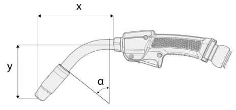
Component selection
The following table provides basic guidance regarding the Flexlite GC component compatibility.
Model | Gas nozzle | Contact tip |
| GC 223GMM | L61 / OD18 / D14 / non-threaded  | 0.8C1 M6 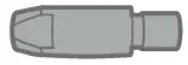 |
| GC 253G | L61 / OD18 / D14 / non-threaded  | 1.0C1 M6 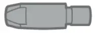 |
| GC 323G | L57 / OD15 / D25 / threaded 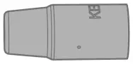 | 1.0C1 M10 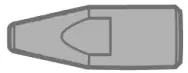 |
The letters in the gas nozzle specification stand for: L = length, OD = outer diameter (at the widest point), D = diameter (inner diameter of the gas nozzle tip).
ORDERING CODES
| Flexlite GC Product | Ordering code | ||
| 3 m: | 3.5 m: | 5 m: | |
| Flexlite GC 253G | – | GC253G35 | GC253G5 |
| Flexlite GC 323G | – | GC323G35 | GC323G5 |
| Flexlite GC 223GMM | GC223GMM3 | – | – |


