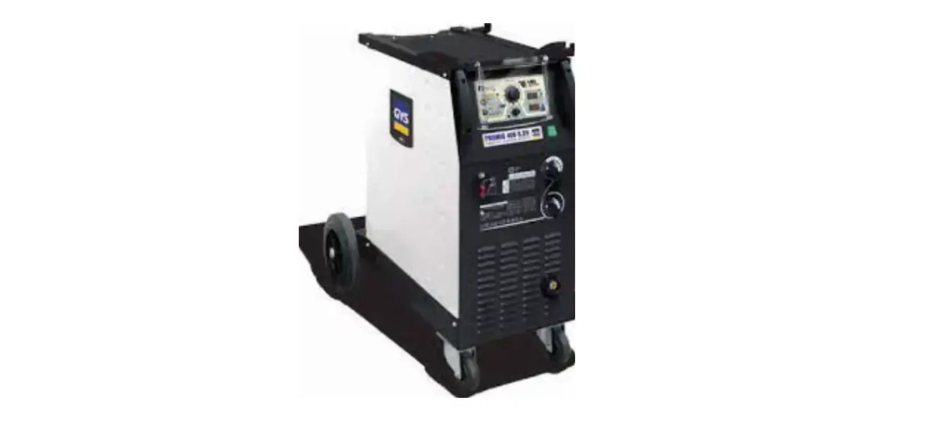
GYS 400T DUO MIG-MAG – TIG – MMA Welding Machine
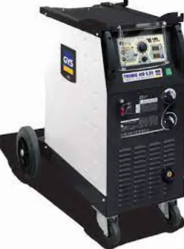
MIG/MAG – TIG – MMA welding machine
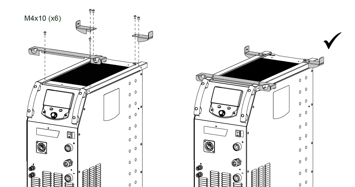
400T W :
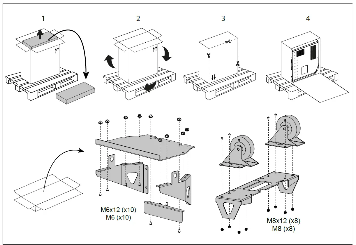
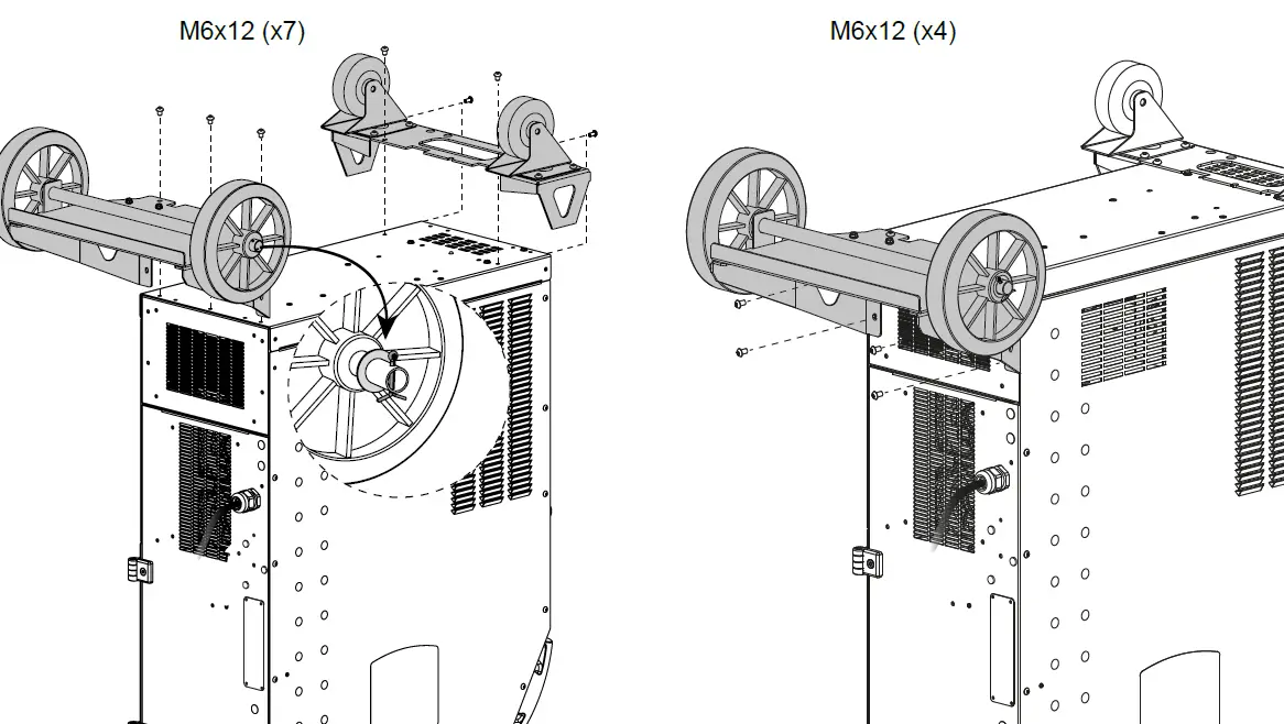
Do not remove the sticker until the wheels are assembled.
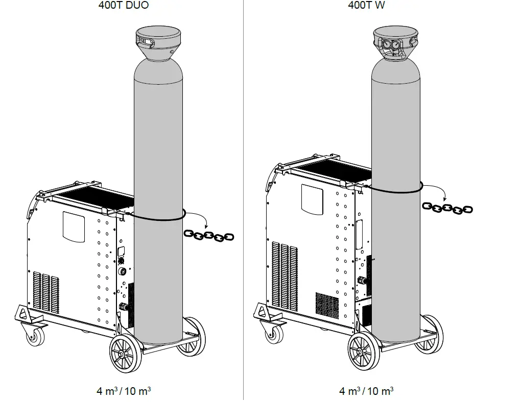
SUPPORT BOUTEILLE
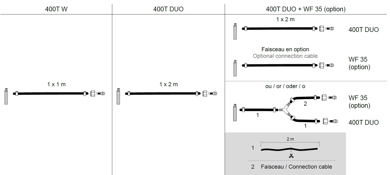
GAS FITTINGS
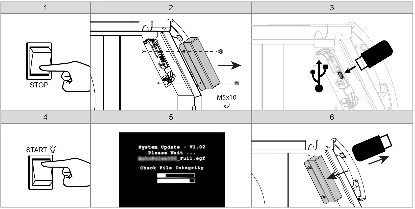
UPDATE PROCEDURE
USB key not included.
Update software available on the GYS website, After sales section.
400T DUO
400T W
WARNINGS – SAFETY INSTRUCTIONS
GENERAL INSTRUCTIONS
 These instructions must be read and fully understood before use.
Do not carry out any alterations or maintenance work that is not directly specified in this manual.
The manufacturer shall not be liable for any damage to persons or property resulting from use not in accordance with the instructions in this manual. In case of problems or queries, please consult a qualified tradesperson to correctly install the product.
ENVIRONMENT
This equipment should only be used for welding operations performed within the limits indicated on the information panel and/or in this manual. These safety guidelines must be observed. The manufacturer cannot be held responsible in the event of improper or dangerous use.
The machine must be set up somewhere free from dust, acid, flammable gases or any other corrosive substances. This also applies to the machine’s storage. Ensure good air circulation when in use.
Temperature range:
- Use between -10 and +40°C (+14 and +104°F).
- Store between -20 and +55°C (-4 and 131°F).
Air humidity:
- Lower than or equal to 50% at 40°C (104°F).
- Lower than or equal to 90% at 20°C (68°F).
Altitude:
- Up to 1000m above sea level (3,280 feet).
PROTECTING YOURSELF AND OTHERS
Arc welding can be dangerous and cause serious injury or death.
Welding exposes people to a dangerous source of heat, light radiation from the arc, electromagnetic fields (caution to those using pacemakers) and risk of electrocution, as well as noise and fumes.
To protect yourself and others, please observe the following safety instructions:
 To protect yourself from burns and radiation, wear insulating, dry and fireproof clothing without lapels. Ensure the clothing is in good condition and that covers the whole body.
 Wear protective gloves which provide electrical and thermal insulation.
 Use welding protection and/or a welding helmet with a sufficient level of protection (depending on the specific use). Protect your eyes during cleaning procedures. Contact lenses are specifically forbidden.
It may be necessary to section off the welding area with fireproof curtains to protect the area from arc radiation and hot spatter. Inform people in the welding area not to stare at the arc rays or molten parts and to wear appropriate clothing for protection. Wear noise protection headphones if the welding process becomes louder than the permissible limit (this is also applicable to anyone else in the welding area).
Keep hands, hair and clothing away from moving parts (the ventilation fan, for example).
Never remove the cooling unit housing protections when the welding power source is live, the manufacturer cannot be held responsible in the event of an accident. Newly welded parts are hot and can cause burns when handled. When maintenance work is carried out on the torch or electrode holder, ensure that it is sufficiently cold by waiting at least 10 minutes before carrying out any work. The cooling unit must be switched on when using a water-cooled torch to ensure that the liquid cannot cause burns.
It is important to secure the working area before leaving it, in order to protect people and property.
 To protect yourself from burns and radiation, wear insulating, dry and fireproof clothing without lapels. Ensure the clothing is in good condition and that covers the whole body.
 Wear protective gloves which provide electrical and thermal insulation.
 Use welding protection and/or a welding helmet with a sufficient level of protection (depending on the specific use). Protect your eyes during cleaning procedures. Contact lenses are specifically forbidden.
 Wear noise protection headphones if the welding process becomes louder than the permissible limit (this is also applicable to anyone else in the welding area).
 Newly welded parts are hot and can cause burns when handled. When maintenance work is carried out on the torch or electrode holder, ensure that it is sufficiently cold by waiting at least 10 minutes before carrying out any work. The cooling unit must be switched on when using a water-cooled torch to ensure that the liquid cannot cause burns.
WELDING FUMES AND GAS
 The fumes, gases and dusts emitted by welding are harmful to health. Sufficient ventilation must be provided and an additional air supply may be required. An air-fed mask could be a solution in situations where there is inadequate ventilation.
Check the extraction system’s performance against the relevant safety standards.
Caution: Welding in confined spaces requires safety monitoring from a safe distance. In addition, the welding of certain materials containing lead, cadmium, zinc, mercury or even beryllium can be particularly harmful. Remove any grease from the parts before welding.
Cylinders should be stored in open or well-ventilated areas. They should be stored in an upright position and kept on a stand or trolley.
RISK OF FIRES AND EXPLOSIONS
 Fully shield the welding area, flammable materials should be kept at least 11 meters away.
Fire fighting equipment should be kept close to wherever the welding activities are being undertaken.
Beware the expulsion of hot spatter or sparks, even through cracks, which can cause fires or explosions.
Keep people, flammable objects and pressurized containers at a safe distance.
Welding in closed containers or tubes is to be avoided. If the containers or tubes are open, they must be emptied of all flammable or explosive materials (oil, fuel, gas residues, etc.).
Grinding work must not be directed towards the source of the welding current or towards any flammable materials.
GAS CYLINDERS
 Gas escaping from cylinders can cause suffocation if there is too high a concentration of it in the welding area (ensure good ventilation).
The machine must be transported in complete safety: gas cylinders must be closed and the welding power source turned off. They should be stored upright and supported to limit the risk of falling.|
Close the cylinder between uses. Beware of temperature variations and exposure to the sun.
The cylinder must not come into contact with flames, arcs, torches, earth clamps or any other sources of heat or ignition.
Be sure to keep it away from electrical and welding circuits. Never weld a pressurized cylinder.
When opening the cylinder valve, keep your head away from the valve and ensure that the gas being used is suitable for the welding process.
ELECTRICAL SAFETY
 The electrical network used must be earthed. Use the recommended fuse size from the rating plate. An electric shock can be the source of a serious accident, whether directly or indirectly, or even death.
Never touch live parts connected to the live current, either inside or outside the power source casing unit (torches, clamps, cables, electrodes), as these items are connected to the welding circuit.
Before opening the welding machine’s power source, disconnect it from the mains and wait two minutes to ensure that all the capacitors have fully discharged.
Do not touch the torch or the electrode holder and the earth clamp at the same time.
If the cables or torches become damaged, they must be replaced by a qualified and authorized person. Measure the cable cross-section according to the intended application. Always use dry and in-fact clothing to insulate yourself from the welding circuit. Alongside this, wear well-insulated footwear in all working environments.
EMC CLASSIFICATION
 This Class A device is not intended for use in a residential environment where power is provided by the public low-voltage local supply network. Ensuring electromagnetic compatibility may be difficult at these sites due to conducted, as well as radiated, radio frequency interference.
Provided that the impedance of the public low-voltage supply network is less than Zmax = 0.29 Ohms at the common coupling point, this equipment complies with IEC 61000-3-11 and can be connected to public low-voltage electrical supply. It is the responsibility of the fitter or operator of the equipment to ensure, by consulting the electricity distribution network provider if necessary, that the network impedance complies with impedance restrictions.
This equipment complies with the IEC 61000-3-12 standard.
ELECTROMAGNETIC INTERFERENCES
 An electric current passing through any conductor produces localized electric and magnetic fields (EMF). The welding current produces an electromagnetic field around the welding circuit and the welding equipment.
Electromagnetic fields (EMFs) can interfere with some medical devices, for example pacemakers. Protective measures must be taken for people with medical implants. For example, restricted access for onlookers or an individual risk assessment for welders.
All welders should use the following guidelines to minimize exposure to the welding circuit’s electromagnetic fields:
- position the welding cables together – securing them with a clamp if possible;
- position yourself (head and body) as far away from the welding circuit as possible,
- never wrap the welding cables around your body,
- do not position yourself between the welding cables. and keep both welding cables on your same side,
- connect the return cable to the workpiece, as close as possible to the area to be welded,
- do not work next to, sit or lean on the source of the welding current,
- do not transport the welding power source or wire feeder while welding.
 Pacemaker users should consult a doctor before using this equipment.
Exposure to electromagnetic fields during welding may have other health effects that are not yet known.
RECOMMENDATIONS FOR ASSESSING THE WELDING AREA AND EQUIPMENT
General Information
It is the user’s responsibility to install and use the arc welding equipment according to the manufacturer’s instructions. If electromagnetic disturbances are detected, it is the user’s responsibility to resolve the situation using the manufacturer’s technical support. In some cases, this corrective action may be as simple as earthing the welding circuit. In other cases, it may be necessary to construct an electromagnetic shield around the welding current source and around the entire workpiece by setting up input filters. In any case, electromagnetic interference should be reduced until it is no longer an inconvenience.
Assessing the welding area
Before installing arc welding equipment, the user should assess the potential electromagnetic problems in the surrounding area. The following should be taken into account:
- the presence of power, control, signal and telephone cables above, below and next to the arc welding equipment,
- radio and television receivers and transmitters,
- computers and other control equipment,
- critical safety equipment, e.g. the protection of industrial equipment,
- the health of nearby persons, e.g. those using of pacemakers or hearing aids,
- the equipment used for calibrating or measuring,
- the protection of other surrounding equipment.
- The operator has to ensure that the devices and equipment used in the same area are compatible with each other. This may require further protective measures;
- the time of day when welding or other operations are to be carried out.
The size of the surrounding area to be taken into account will depend on the building’s structure and the other activities taking place there. The surrounding area may extend beyond the boundaries of the premises.
Assessment of the welding equipment
In addition to the assessment of the surrounding area, the arc welding equipment’s assessment can be used to identify and resolve cases of interference. It is appropriate that the assessment of any emissions should include in situ procedures as specified in Article 10 of CISPR 11. In situ measurements can also be used to confirm the effectiveness of mitigation measures.
GUIDELINES ON HOW TO REDUCE ELECTROMAGNETIC EMISSIONS
- The mains power grid: Arc welding equipment should be connected to the mains power grid according to the manufacturer’s recommendations. If any interference occurs, it may be necessary to take additional precautionary measures such as filtering the mains power supply. Consider protecting the power cables of permanently installed arc welding equipment within a metal pipe or a similar casing. The power cable should be protected along its entire length. The shield should be connected to the welding power source to ensure that there is good electrical contact between the conduit and the welding power source enclosure.
- The maintenance of arc welding equipment: Arc welding equipment should be subject to routine maintenance as recommended by the manufacturer. All access points, service openings and bonnets should be closed and properly locked when the arc welding equipment is in use. The arc welding equipment should not be modified in any way, except for those modifications and adjustments mentioned in the manufacturer’s instructions. The spark gap of arc starters and stabilizers should be adjusted and maintained according to the manufacturer’s recommendations.
- Welding cables: Cables should be as short as possible, placed close together either near or on the ground.
- Equipotential bonding: Consideration should be given to linking all metal objects in the surrounding area. However, metal objects connected to the workpiece increase the risk of electric shocks to the user if they touch both these metal parts and the electrode. It is necessary to insulate the operator from such metal objects.
- Earthing the workpiece: In cases where the part to be welded is unearthed for electrical safety reasons or due to its size and location, such as ship hulls or structural steel buildings, an earthed connection can reduce emissions in some cases, although not always. Care should be taken to avoid the earthing of parts which could increase the risk of injury to users or damage to other electrical equipment. If necessary, the workpiece’s connection should be earthed directly, but in some countries where a direct connection is not allowed, the connection should be made with a suitable capacitor chosen according to national regulations.
- Protection and protective casing: The selective protection and encasing of other cables and equipment in the surrounding area may limit interference problems. The safeguarding of the entire welding area may be considered for special applications.
THE TRANSPORTING AND MOVING OF THE MACHINE’S POWER SOURCE
Do not use the cables or torch to move the welding power source. It should be moved in an upright position. Do not carry or transport the power source overhead of people or objects.
Never lift a gas cylinder and the welding power source at the same time. Their transportation requirements are different.
It is advisable to remove the wire spool before lifting or transporting the welding power source.
SETTING UP THE EQUIPMENT
- Place the welding power source on a floor with a maximum inclination of 10°.
- Provide sufficient space to ventilate the welding power source and access the controls.
- Do not use in an area with conductive metal dust.
- The welding power source should be protected from heavy rain and not exposed to direct sunlight.
- The machine is IP23S rated, meaning:
- its dangerous parts are protected from being entered by objects greater than 12.5 mm and,
- it is protected against rain falling at an angle of up to 60° from vertical, providing that any moving parts (fan) are stationary. This product can therefore be stored outdoors in accordance with the IP23 protection rating.
Stray welding currents can destroy earthing conductors, damage electrical equipment and devices and cause component parts to overheat leading to fires.
- All welding connections must be firmly secured and regularly checked!
- Make sure that the item’s attachment is firm and secure, without any electrical problems!
- Join together or suspend any electrically conductive parts of the welding source such as the frame, trolley and lifting systems so that they are insulated!
- Do not place other equipment such as drills or grinding devices etc. on the welding source, trolley, or lifting systems unless they are insulated!
- Always place welding torches or electrode holders on an insulated surface when not in use!
The power cables, extensions and welding cables must be fully uncoiled to prevent overheating.The manufacturer assumes no responsibility for damage to persons or objects caused by improper and dangerous use of this equipment.
MAINTENANCE / RECOMMENDATIONS
 Maintenance should only be carried out by a qualified person. Annual maintenance is recommended.
- Switch off the power supply by pulling the plug and wait two minutes before working on the equipment.. Inside the machine, the voltages and currents are high and dangerous.
- Regularly remove the cover and blow out any dust. Take advantage of the opportunity to have the electrical connections checked with an insulated tool by a qualified professional.
- Regularly check the condition of the power cable. If the power cable is damaged, it must be replaced by the manufacturer, the after sales service team or an equally qualified person to avoid any danger.
- Leave the welding power source vents free for air intake and outflow.
- Do not use this welding power source for thawing pipes, recharging batteries/storage batteries or starter motors.
 400T-W :
The coolant should be changed every 12 months to prevent residue from clogging the torch’s cooling system. Any leaks or pro-duct residues found after use, must be treated in an appropriate treatment plant. If possible, the product should be recycled. It is forbidden to drain the used material into waterways, pits or drainage systems. Diluted fluid should not be emptied into the sewage system, except where allowed under local regulations.
 Maintenance should only be carried out by a qualified person. Annual maintenance is recommended.
 400T-W :
INSTALLATION – USING THE PRODUCT
Only experienced personnel, authorized by the manufacturer, may carry out the machine’s set-up. During set-up, ensure that the power source is unplugged from the mains. Series or parallel power source connections are not allowed. It is recommended to use the welding cables supplied with the unit in order to obtain the best possible product performance.
DESCRIPTION
This machine is a three-phase power source for semi-automatic, software-supported welding (MIG or MAG), coated electrode welding (MMA) and refractory electrode welding (TIG). It accepts 200 and 300 mm diameter wire spools.
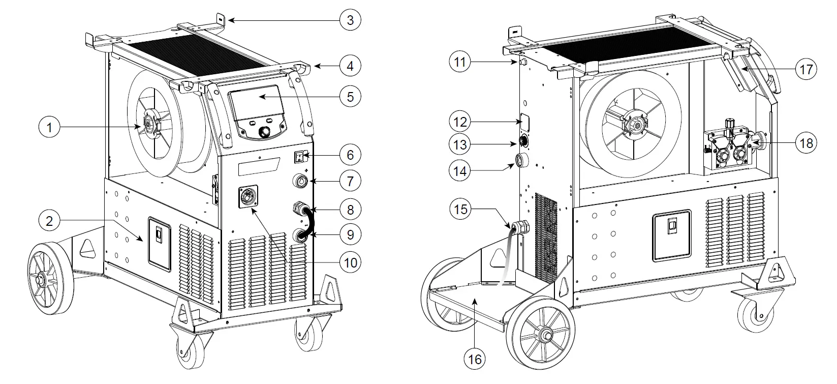
DESCRIPTION OF THE EQUIPMENT (II)
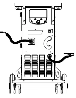
400T-DUO
- Reel support Ø 200/300 mm
- Accessory box hatch
- Cable support
- Torch support
- HMI (Human Machine Interface)
- START/STOP switch
- Positive polarity socket
- Polarity reversal cable
- Negative polarity socket
- Euro connector (torche)
- Gas connector
- Cover option
- Connector for external wire feeder control
- Positive polarity socket
- Mains cable (5 m)
- Bottle holder 4m3 or 10m3
- USB hatch
- Wire-feed motor
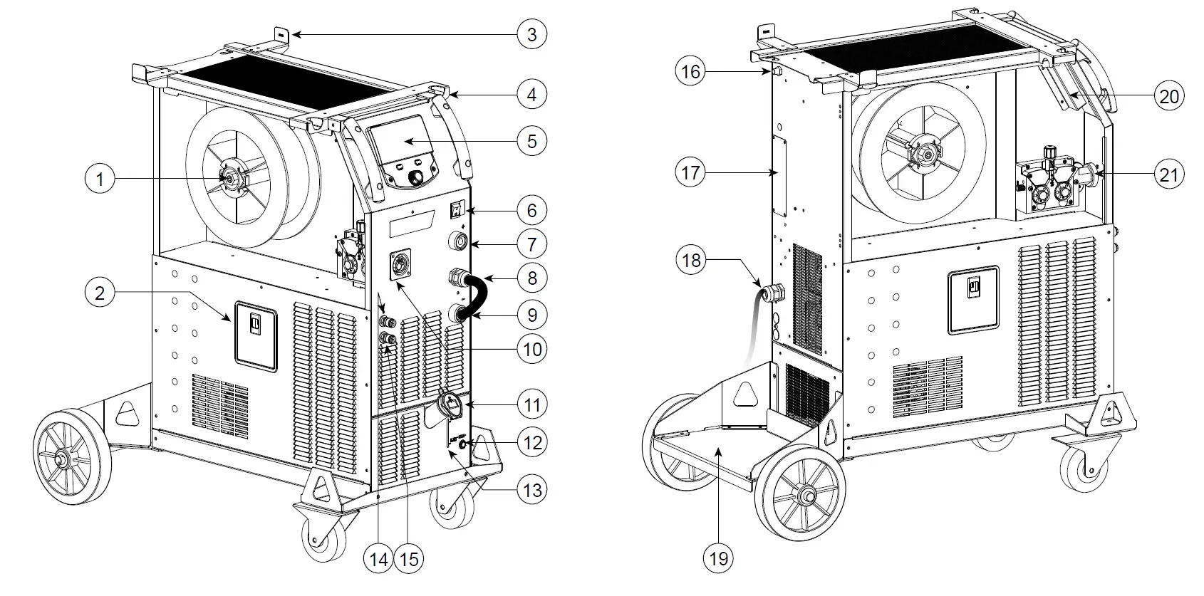
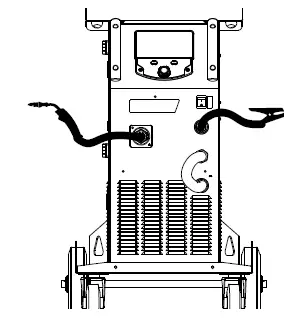
400T-W
- Reel support Ø 200/300 mm
- Accessory box hatch
- Cable support
- Torch support
- HMI (Human Machine Interface)
- START/STOP switch
- Positive polarity socket
- Polarity reversal cable
- Negative polarity socket
- Euro connector (torche)
- Filling cap
- Fuse for cooling unit
- Tank level indicator
- Liquid coolant outlet (Blue)
- Liquid coolant outlet (Red)
- Gas connector
- Cover option
- Mains cable (5 m)
- Bottle holder 4m3 or 10m3
- USB hatch
- Wire-feed motor
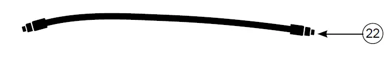
- Priming hose
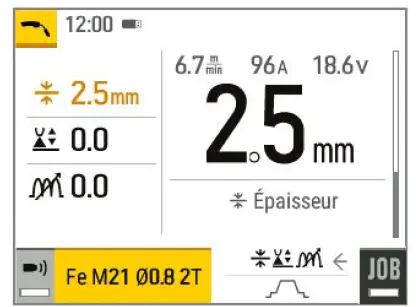
HUMAN-MACHINE INTERFACE (HMI)
 Please read the Interface User Guide (HMI) which forms part of the complete product literature.
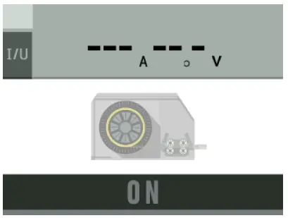
POWER SWITCH
This machine is fitted with a 32A socket type EN 60309-1 which must only be used on a three-phase 400 V (50-60 Hz) four-wire earthed electrical installation.
The absorbed effective current (I1eff) is indicated on the device for optimum operating conditions. Check that the power supply and its safeguards (fuse and/or circuit breaker) are compatible with the electric current being used. In some countries, it may be necessary to change the plug to allow the use at maximum settings.
- The power source is designed to operate at 400 V +/- 15%. The unit enters protection mode if the supply voltage
is less than 330Vrms or greater than 490Vrms. (An error code will appear on the display screen). - Starting is done by pressing the START/STOP switch (On), and stopping is done by pressing the same switch (Off). Warning! Never switch off the power supply while the unit is under load.
CONNECTING TO A POWER SOURCE
This equipment can be operated with electric generators provided that the auxiliary power supply meets the following requirements:
- The voltage must be alternating with an RMS value of 400V +/- 15% and a peak voltage of less than 700V.
- The frequency must be between 50 and 60 Hz.
It is vital to check these conditions as many generators produce high voltage peaks that can damage equipment.
USING EXTENSION LEADS
All extension leads must be of a suitable length and width that is appropriate to the equipment’s voltage. Use an extension lead that complies with national safety regulations.
| Input voltage | Length – Cross-section of the extension cable (Length < 45m) |
| 400 V | 4mm² |
SETTING UP THE REEL
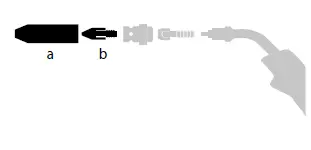 Remove the nozzle (a) and contact tube (b) from your MIG/MAG torch.
Open the power source’s hatch.
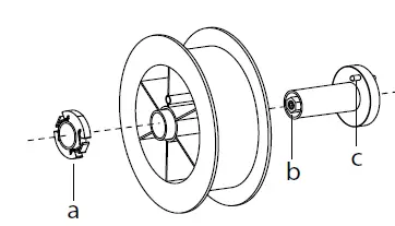
- Position the reel on its holder.
- Take into consideration the reel stands’s drive lug (c). To fit a 200 mm reel, tighten the plastic reel holder (a) to the maximum.
- Adjust the brake wheel (b) to prevent the non-moving spool from tangling the wire when the welding stops. Do not over tighten as this will cause the power source to overheat.
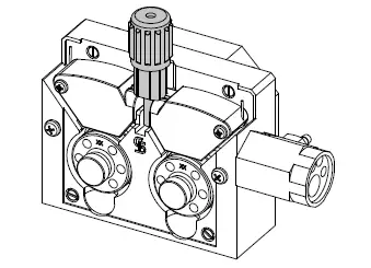
LOADING THE FILLER WIRE
To change the rollers, do the following:
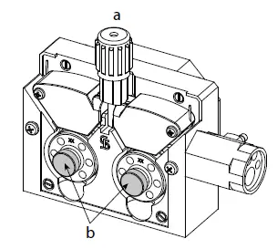
- Loosen the knob (a) to the maximum and lower it.
- Unlock the rollers by removing the retaining screws (b)
- Fit the appropriate drive rollers for your application and retighten the retaining screws. The rollers supplied are double groove rollers :
- steel Ø 1.0/1.2
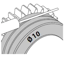
- Check the inscription on the roller to ensure that the rollers are suitable for the wire diameter and the wire material (for Ø 1.0 wire, use the Ø 1.0 groove).
- Use V-grooved rollers for steel and other hard wires.
- Use U-grooved rollers for aluminium and other soft, alloyed wires.
- visible inscription on the roller (example: 10 = Ø 1.0)
To install the wire, follow the steps below:
- Loosen the knob to the maximum and lower it.
- Insert the wire, then close the motor reel and tighten the knob as shown.
- Press the trigger of the torch to activate the motor, and the procedure will be displayed on the screen..
Notes:
- Too narrow a sheath can lead to unreeling issues and can lead to the overheating of the motor.
- The torch connection must also be properly tightened to prevent it from overheating.
- Ensure that neither the wire, nor the reel, touches the device’s mechanism, otherwise there is a danger of short-circuiting the ma-chine.
RISK OF INJURY FROM MOVING COMPONENTS
The reels have moving parts that can trap hands, hair, clothing or tools causing injuries!
- Do not touch rotating, moving or driving parts of the machine!
- Ensure that the housing covers or protective covers remain fully closed when in operation.
- Do not wear gloves when threading the filler wire or changing the filler-wire’s spool
COOLANT PUMP PRIMING (400T-W)
When using the product for the first time, or after completely emptying the coolant tank, the following procedure must be followed to start the circulation:
- Fill the coolant reservoir to its maximum level. The tank has a 5.5 litre capacity.
- Connect the priming hose (II-ww) to the coolant outlet connector (I-14) and place the other end in an empty container (ideally a bottle).
- Turn on the power source.
- In the «System/Cooling unit» menu, press push-button no. 2 (
 ) to start the priming procedure.
 - Once the pump is primed (container is filling with coolant), stop the cooling unit by pressing one of the buttons on the HMI.
- Disconnect the priming hose and return the liquid to the cooling system: the pump is now primed.
LIQUID COOLING (400T-W)
FILLING
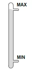 The cooling unit tank must be filled to the MAX level indicated by the gauge on the front, and must never be allowed to fall below the MIN level. A warning message will be triggered if this occurs.
It is essential to use a specific coolant for welding machines that has low electrical conductivity as well as being anti-corrosion and anti-freeze (ref. 052246).
The use of other coolants, in particular the standard automotive coolants, can lead to the accumulation of solid deposits in the cooling system through electrolysis, thus degrading the cooling system and even clogging it entirely.
This recommended MAX level is essential for optimum performance of the liquid-cooled torch.
Any damage to the machine caused by the use of a coolant other than the recommended variety will not be covered under the warranty..
USAGE
- NEVER USE the machine’s power source WITHOUT COOLING LIQUID while the pump is running.
Meet the minimum coolant level. Failure to do so may result in permanent damage to the cooling system pump. - Ensure that the cooling unit is switched off before disconnecting the torch’s fluid inlet and/or outlet pipes. Coolant is harmful and irritates the eyes, mucous membranes and skin. Hot liquid can cause burns.
- Danger of burns from hot liquid. Never drain the cooling unit after use. The liquid inside the machine is boiling hot, wait for it to cool before draining.
In «AUTO» mode, the cooler pump starts running when welding is started. When welding stops, the pump continues to run for a further 10 minutes. During this time, the liquid cools the welding torch bringing it back to room temperature. Leave the power source plugged in for a few minutes after welding to allow it to cool.
In the MIG-MAG process, the cooling system is activated by default (AUTO). To use an air-cooled MIG-MAG torch, it is necessary to switch the cooling system off. Please refer to the interface manual to do this.
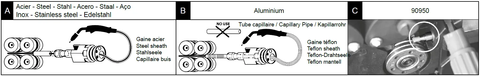
SEMI-AUTOMATIC STEEL/STAINLESS STEEL WELDING (MAG MODE)
This machine can weld steel and stainless steel wire from Ø 0.6 to 1.2mm (I-A). The unit is supplied with Ø 1.0/1.2 rollers for steel or stainless steel as standard. The contact tip, the grooved roller, and the torch sheath are designed for this application.
For operation on steel, a specific welding gas (Ar+CO2) is required. The amount of CO2 may vary depending on the type of gas used. For stainless steel, use a 2% CO2 mixture. When welding with pure CO2, it is necessary to connect a gas pre-heater to the gas cylinder. For specific gas issues, please contact your gas distributor. The gas flow rate for steel is between 8 and 15 litres per minute depending on the surroundings. To check the gas flow rate on the manometer without unwinding the welding wire, press and hold push-button n°1 and follow the procedure on the screen. This check should be done periodically to ensure the best possible welding. Refer to the HMI manual.
SEMI-AUTOMATIC ALUMINIUM WELDING (MIG MODE)
The unit can weld aluminum wire from Ø 0.8 to 1.2mm (I-B).
For use with aluminum, pure argon gas (Ar) is required. Seek advice from a gas distributor for a wide selection of gases. The gas flow rate for aluminum is between 15 and 20 l/min depending on the surrounding environment and the welder’s experience.
The differences between steel and aluminum processing are as follows:
- Use specific rollers for aluminum welding.
- Put minimum pressure on the motorized reel’s pressure rollers so as not to crush the thread.
- Only use the capillary tube (for guiding the wire between the feed rollers and the EURO connector) for steel/stainless steel welding (I-B)
- Use a special aluminum torch. This aluminum torch has a Teflon coating to reduce friction. DO NOT cut away the coating at the tip of the connector! This coating is used to guide the wire from the rollers.
- Contact tips: use a SPECIAL aluminum contact tip that matches the wire’s diameter.
 When using red or blue sheathing (for aluminum welding), it is recommended to use the accessory 90950 (I-C). This stainless steel sheath guide improves the centering of the sheath and facilitates the flow of the wire.
Video
SEMI-AUTOMATIC WELDING IN CUSI AND CUAL (BRAZING MODE)
The unit can weld Ø 0.8 and 1.0 mm CuSi and CuAl wire.
In the same way as with steel, a capillary tube must be set up and a torch with a steel sheath must be used. For brazing, pure argon (Ar) should be used.
SEMI-AUTOMATIC WELDING WITH CORED WIRE
The unit can weld flux-cored wire from Ø 0.9 to 1.6mm. The original rollers must be replaced by specific cored wire rollers (available as an optional extra). Welding flux-cored wire with a standard nozzle can lead to overheating and damage to the torch. Remove the original nozzle from your MIG-MAG torch.
CHOOSING A POLARITY
Polarity +
Gas-shielded MIG/MAG welding generally requires positive polarity.
Polarity –
MIG/MAG welding without gas shielding (No Gas) generally requires negative polarity.
In any case, refer to the wire manufacturer’s recommendations for the choice of polarity for your MIG-MAG torch.
GAS SUPPLY
- Fit a suitable pressure regulator to the gas cylinder. Connect it to the welding station with the pipe supplied. Attach the two hose clamps to prevent leaks.
- Ensure that the gas cylinder is held securely in place with a chain attached to the power source.
- Set the gas flow rate by adjusting the dial on the pressure regulator.
NB: To adjust the gas flow rate more easily, use the rollers on the motorised spool by pulling the trigger on the torch (loosen the brake wheel on the motorised reel so that no wire is drawn in). Maximum gas pressure: 0.5 MPa (5 bar).
This procedure does not apply to welding in «No Gas» mode.
RECOMMENDED COMBINATIONS
|
| Current (A) | Ø Wire (mm) | Ø Nozzle (mm) | Flow (L/min) | |
| MIG | 0.8-2 | 20-100 | 0.8 | 12 | 10-12 |
| 2-4 | 100-200 | 1.0 | 12-15 | 12-15 | |
| 4-8 | 200-300 | 1.0/1.2 | 15-16 | 15-18 | |
| 8-15 | 300-500 | 1.2/1.6 | 16 | 18-25 | |
| MAG | 0.6-1.5 | 15-80 | 0.6 | 12 | 8-10 |
| 1.5-3 | 80-150 | 0.8 | 12-15 | 10-12 | |
| 3-8 | 150-300 | 1.0/1.2 | 15-16 | 12-15 | |
| 8-20 | 300-500 | 1.2/1.6 | 16 | 15-18 |
 (mm)
(mm)MIG / MAG (GMAW/FCAW) WELDING MODE
| Welding processes | ||||
| Settings | Settings | Manual | Synergies (pre-installed user settings) | |
| Torque material/gas | – FeAr 15% CO2 – … | – |  | Choice of the material to be welded. Synergic welding parameters |
| Wire diameter | Ø 0.8 > Ø 1.6mm | – | | Choice of wire diameter |
| Using the trigger | 2T, 4T |
|
| Choice of trigger welding management mode |
| Spot mode | Spot, Spot-Delay | Selecting the spot mode | ||
| First Setting | Thickness Start-up Speed | – | | Choosing the main setting to be displayed (thickness of the workpiece, average welding current or wire speed). |
Access to some of the welding parameters depends on the selected display mode: Settings/Display mode: Easy or Expert. Refer to the HMI manual.
WELDING PROCESSES
For more information on GYS pre-installed user settings and welding processes, scan the QR code:

SPOT WELDING MODE
- Spot
This welding mode allows the pre-assembly of parts before welding. Spot welding can be done manually using the trigger or timed with a predefined spot welding period. Spot welding allows for better reproduction and non-oxidised weld points. - Spot-Delay
This is a welding mode similar to Spot welding but with predefined weld and dwell times, as long as the trigger is held down. This function allows welding very thin steel or aluminum metal sheet, limiting the risk of piercing and distortion (especially for aluminum welding).
CONFIGURING THE SETTINGS
| Units | ||
| Burnback | – | Feature to help prevent the wire sticking to the bead. This is timed to coincide with the wire rising from the weld pool. |
| Crater Filler | %/s | This idling current is the next phase after the current is lowered. The intensity (% of welding current) and the time (seconds) can be programmed. |
| Delay | s | Time between the end of a point (excluding Post-Gas) and the start of a new point (including Pre-Gas). |
| Thickness | mm | The pre-installed user settings (syngergies) allow for a fully-automatic set-up. Changing the thickness setting automatically sets the appropriate wire tension and speed. |
| Crater-fill feature | s | Downslope current. |
| Hot Start | %/s | The Hot Start is an overcurrent used at the start that prevents the wire from sticking to the workpiece. The intensity (% of welding current) and the time (seconds) can be programmed. |
| Current | A | The welding current is adjusted according to the type of wire used and the material to be welded. |
| I Start | – | Adjustment of the ignition current. |
| Arc length | – | Used to adjust the distance between the end of the wire and the weld pool (tension adjustment). |
| Pre-Gas | s | When the torch is bled and the gas shield is created before ignition. |
| Tack welding | s | Set duration. |
| Post-Gas | s | Duration of the gas protection after the arc is extinguished. It protects the workpiece and the electrode from oxidation. |
| Self-Induction Coil | – | Lessens the welding current more or less. To be set according to the welding position. |
| Spot welding | s | Set duration. |
| Voltage | V | Control over the cord’s width. |
| Upslope | s | Upslope current |
| Approach speed | – | Progressive yarn speed. Before priming, the wire moves slowly to create the first contact without jolting. |
| Wire speed | m/min | Amount of filler metal deposited and consequently the welding intensity and penetration. |
Access to some of the welding settings depends on the selected welding process (Manual, Standard, etc.) and the selected display mode (Easy, Expert or Advanced). Refer to the HMI manual.
GAS FLOW CONTROL
To check the gas flow rate on the manometer without unwinding the welding wire, press and hold push-button n°1 and follow the procedure on the screen. This check should be done periodically to ensure the best possible welding. Refer to the HMI manual.
TIG (GTAW) WELDING MODE
INSTALLATION AND GUIDANCE
- DC TIG welding requires a protective gas shield (Argon).
- Connect the earth clamp to the positive (+) plug connector. Connect the optional TIG torch (ref. 046108) into the EURO connector of the power source and the polarity reversal cable into the negative (-) socket.
- Ensure that the torch is properly fitted and that the consumables (vice grip pliers, collet bodies, diffusers and nozzles) are not worn out.
- The choice of electrode will depend on the current of the DC TIG process.
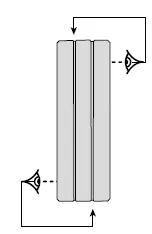
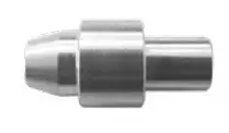
ELECTRODE SHARPENING
For optimum results, it is advised to use an electrode sharpened in the following way:
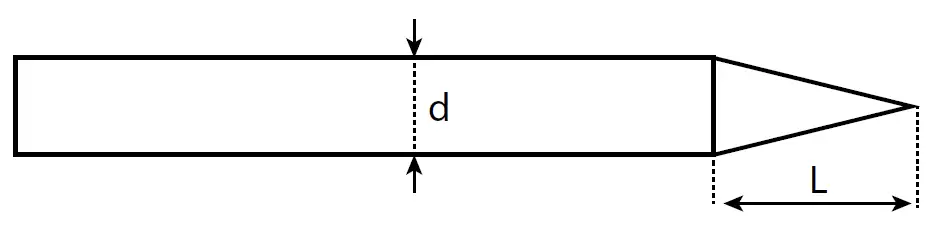
- L = 3 x d for a low current.
- L = d for a high current
RECOMMENDED COMBINATIONS
|
| Current (A) | Ø Electrode (mm) | Ø Nozzle (mm) | Argon flow rate (L/min) |
| 0.3 – 3 | 3 – 75 | 1 | 6.5 | 6 – 7 |
| 2.4 – 6 | 60 – 150 | 1.6 | 8 | 6 – 7 |
| 4 – 8 | 100 – 200 | 2 | 9.5 | 7 – 8 |
| 6.8 – 8.8 | 170 – 250 | 2.4 | 11 | 8 – 9 |
| 9 – 12 | 225 – 300 | 3.2 | 12.5 | 9 – 10 |
PROCESS SETTINGS
Access to some of the welding parameters depends on the selected display mode: Settings/Display mode: Easy or Expert. Refer to the HMI ma-nual.
| Settings | Settings | |
|
Welding process | Standard | Smooth current |
| Pulsed | Pulsed current | |
| Spot welding | Smooth tacking | |
| Spot-Pulse | Pulsed tacking | |
| Trigger mode | 2T, 4T, Valve | Choice of trigger welding management mode. |
SETTINGS
- Standard
The standard DC TIG welding process allows high quality welding on most ferrous materials such as steel and stainless steel, but also copper and its alloys including titanium. The various current and gas management possibilities allow you to perfectly control your welding operation, from priming to the final cooling of your weld seam. - Pulse
This pulsed current welding mode combines high current pulses (I = welding pulses) with low current pulses (cold I, workpiece cooling pulses). The pulsed mode allows parts to be assembled while limiting temperature rises and warping. Ideal for on site use.
Example:
The welding current (I) is set to 100 A and % (cold I) = 50%, i.e. cold current = 50% x 100 A = 50.
F(Hz) is set to 10 Hz, the signal period will be 1/10 Hz = 100 ms -> a 100 A pulse every 100 ms then followed by another at 50 A.
- Spot
This welding mode allows the pre-assembly of parts before welding. Spot welding can be done manually using the trigger or timed with a predefined spot welding period. Spot welding allows for better reproduction and non-oxidized weld points. - Spot-Pulse
This method of welding is used to pre-assemble thin sheet metal workpieces prior to the actual welding process. Spot welding can be done manually using the trigger or timed with a predefined spot welding period. Spot welding allows for better reproduction and non-oxidized weld points.
CHOOSING THE ELECTRODE’S DIAMETER
| Electrode Ø (mm) | DC TIG | |
| Pure tungsten | Tungsten with oxides | |
| 1 | 10 > 75 | 10 > 75 |
| 1.6 | 60 > 150 | 60 > 150 |
| 2 | 75 > 180 | 100 > 200 |
| 2.5 | 130 > 230 | 170 > 250 |
| 3.2 | 160 > 310 | 225 > 330 |
| Approx. = 80 A per mm Ø | ||
USING THE TRIGGER
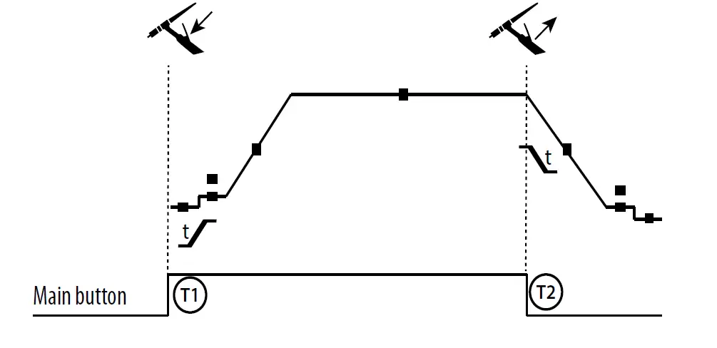
- 2T
 T1 – The main button is pressed, the welding cycle starts (Pre-Gas, I_Start, upslope and welding).
T2 – The main button is released, the welding cycle is stopped
(downslope, I_Stop, Post-Gas).
For two-button torches in T2 only, the secondary button is treated as the main button. - 4T

T1 – The main button is pressed, the cycle starts from Pre-Gas and stops at the Instar phase.
T2 – The main button is released, the cycle continues to upslope and welding.
T3 – The main button is pressed, the cycle goes to downslope and stops in the I Stop phase.
T4 – The main button is released, the cycle ends with the Post-Gas. NB: for torches, double buttons and double button + potentiometer => «up/weld current» button turns on the potentiometer, the «down» button turns it off.
 T1 – The main button is pressed, the welding cycle starts (Pre-Gas, I_Start, upslope and welding).
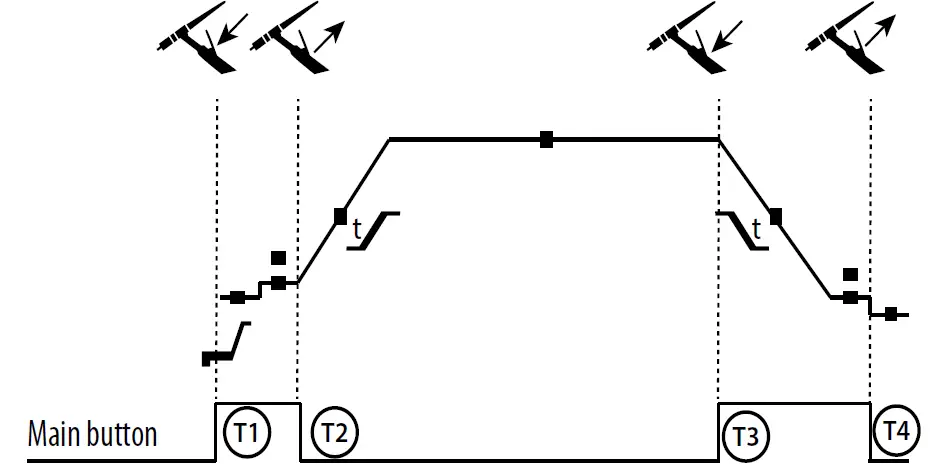
For dual button or dual trigger torches, the «high» trigger retains the same functionality as the single trigger torch . The «low» trigger is not active.
CONFIGURING THE SETTINGS
| Units | ||
| End current | % | This idling current is the next phase after the current is lowered. |
| Starting current | % | This start-up bearing current is a warm-up phase before the current is raised. |
| Welding current | A | Welding current. |
| Cold current | % | Second welding current known as a «cold» welding current. |
| Pulse duration | s | Manual or time-controlled spot pulse phase |
| Spot duration | s | Either manual or a set time. |
| Crater-fill feature | s | Avoids cratering at the end of welding and the risk of cracking, particularly in light alloys. |
| Pulse frequency | Hz | Pulse frequency (setting guidelines):
|
| Rising current | s | Allows a gradual increase in welding current. |
| Post-Gas | s | Duration of the gas protection after the arc is extinguished. It protects the workpiece and the electrode from oxidation during cooling. |
| Pre-Gas | s | When the torch is bled and the gas shield is created before ignition. |
| Stopping time | s | This idling time is a phase that comes after the current is lowered. |
| Starting time | s | Starting time before the current is raised. |
| Cold weather | % | Pulsed hot current (I) time balance |
Access to some of the welding parameters depends on the selected display mode: Settings/Display mode: Easy or Expert. Refer to the HMI manual.
MANUAL GAS PURGE
The presence of oxygen in the torch can lead to a decrease in mechanical quality and can result in less corrosion resistance. To flush the gas from the torch, press and hold button no. 1 and follow the on-screen procedure. Refer to the HMI manual.
MMA (SMAW) WELDING MODE
INSTALLATION AND GUIDANCE
- Plug the cables, electrode holder and earth clamp into the plug connections.
- Respect the electrical polarities and the strength of the welding power indicated on the electrode boxes.
- Remove the coated electrode from the electrode holder when the welding power source is not in use.
- The equipment is fitted with 3 inverter-specific features:
- Hot Start provides an overcurrent at the beginning of the welding process.
- Arc Force creates an overcurrent which prevents the electrode from sticking to the weld pool.
- The Anti-Stick technology makes it easier to unstick the electrode from the metal.
PROCESS SETTINGS
| Welding processes | ||||
| Settings | Settings | Standard | Pulsed | |
| Electrode typ | Rutile Basic | | | The type of electrode determines the settings in order to optimize its weldability depending on the type of electrode used. |
| Anti-Sticking | ON-OFF | | | The anti-stick feature is recommended to safely remove the electrode in the event of it sticking to the workpiece (the current is cut off automatically). |
Access to some of the welding parameters depends on the selected display mode: Settings/Display mode: Easy or Expert. Refer to the HMI ma-nual.
WELDING PROCESSES
- Standard
This standard MMA welding mode is suitable for most welding applications. It enables welding with all types of coated, rutile, basic and cellulosic electrodes, as well as on all materials: steel, stainless steel and cast iron. - Pulse
The pulsed MMA welding mode is suitable for upright (PF) applications. The pulsed setting keeps the weld pool cold while promoting material transfer. Without pulsing, vertical upward welding requires a ‘Christmas tree’ movement, i.e. a difficult triangular movement. Thanks to Pulsed MMA welding, it is no longer necessary to perform this movement. Depending on the thickness of your workpiece, a straight upward movement should suffice. However, if you want to enlarge your weld pool, a simple sideways movement similar to doweled welding is sufficient.. In this case, you can set the frequency of your pulsed current on the display screen. This method offers greater control of the vertical welding operation.
CHOOSING COATED ELECTRODES
- Rutile electrodes: very easy to use in any position.
- Basic electrodes: it can be used in all positions and is suitable for safety work due to its increased mechanical properties.
CONFIGURING THE SETTINGS
| Units | ||
| Arc Force | Arc Force is an overcurrent administered to prevent sticking when the electrode or weld bead touches the weld pool. | |
| Welding current | A | The welding current is determined by the type of electrode chosen (see electrode packaging). |
| Duration of Hot Start | s | Hot Start is an overcurrent at the ignition stage which prevents the electrode from sticking to the workpiece. The intensity (% of welding current) and the time (seconds) can be programmed. |
| Pulse frequency | Hz | PULSE mode’s PULSING frequency. |
| Percentage Hot Start | % | Hot Start is an overcurrent at the ignition stage which prevents the electrode from sticking to the workpiece. The intensity (% of welding current) and the time (seconds) can be programmed. |
| Percentage I cold | % | |
| Cold weather | s |
Access to some of the welding parameters depends on the selected display mode: Settings/Display mode: Easy or Expert. Refer to the HMI ma-nual.
ADJUSTING THE WELDING INTENSITY
The following settings correspond to the applicable current range depending on the type and diameter of the electrode used. These ranges are quite large as they depend on the usage and the welding position.
| electrode Ø (mm) | Rutile E6013 (A) | Basic E7018 (A) |
| 1.6 | 30-60 | 30-55 |
| 2.0 | 50-70 | 50-80 |
| 2.5 | 60-100 | 80-110 |
| 3.15 | 80-150 | 90-140 |
| 4.0 | 100-200 | 125-210 |
| 5 | 150-290 | 200-260 |
| 6.3 | 200-385 | 220-340 |
ADJUSTING THE ARC FORCE
It is advisable to set the Arc Force to the middle position (0) to start welding and then adjust it according to the results obtained and individual welding preferences. Note: The adjustment range of the Arc Force is specific to the type of electrode chosen.
ROLLERS (B) OPTIONAL
| Diameter | Reference (x2) | Diameter | Reference (x2) | ||
| Steel | Aluminum | Flux-cored wire | |||
| ø 0.6/0.8 | 042353 | – | ø 0.9/1.2 | 042407 | |
| ø 0.8/1.0 | 042360 | 042377 | |||
| ø 1.0/1.2 | 046849 | 040915 | |||
SEPARATE WIRE FEEDER WF 35
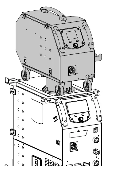
The KRONOS 400T DUO product can be fitted with a separate WF 35 wire feeder (option, ref. 075078) in order to quickly use 2 different wire types or diameters without changing torches or spools. The connection between these two parts is made through a dedicated cable link, available separately:
| Type of torch cooling | Length | Section | Reference |
| Air | 5m | 70mm² | 075443 |
| 10m | 70mm² | 075450 | |
| 95mm² | 077553 | ||
|
Water | 1.8m | 70mm² | 075467 |
| 5m | 70mm² | 075474 | |
| 10m | 70mm² | 075481 | |
| 95mm² | 075504 |
For connecting the interconnection between the power source and the wire feeder, refer to the wire feeder manual.
HMI – wire feeder active
 HMI – wire feeder inactive
To switch from an inactive wire feeder to an active wire feeder, press the trigger on the non-active torch or press the thumbwheel on the non-active display.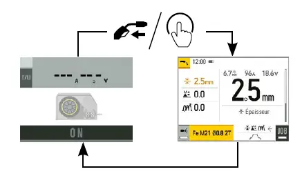
DEFECTS: CAUSES & SOLUTIONS
No current or wrong welding current. Incorrect mains outlet connection. The wire jams after passing through the rollers. Crushed wire guide sheath. The weld bead is porous. The gas flow is insufficient. Excessive sparks. Arc voltage is too low or too high. No gas coming from the torch. Poor gas connection. Error while downloading. The data on the USB stick is incorrect or corrupted. Backup error. You have exceeded the maximum number of backups. Automatic deletion of JOBS. Some of your JOBs have been deleted because they were incompatible with the new pre-installed user settings (synergies). USB key error. There is no JOB detected on the USB stick. File error. The file does not match the pre-installed user settings (synergies) downloaded to the product. Update problem The USB stick is not recognized. The visualization of step 5 of the update procedure does not appear on the display.
| SYMPTOMS | POSSIBLE CAUSES | SOLUTIONS |
|
The flow rate of the welding wire is not constant. | Clogs blocking the opening. | Clean the contact tube or replace it with non- stick material. |
| The wire is slipping on the rollers. | Reapply the non-stick product. | |
| One of the rollers is spinning. | Check the tightness of the roller screw. | |
| The torch cable is twisted. | The torch cable should be as straight as possible. | |
| The unwinding mechanism is not working. | The spool’s brake or roller is too tight. | Loosen the brake and rollers. |
| Incorrect unwinding of the wire. | Dirty or damaged wire guide. | Clean or replace. |
| Roller pin key is missing. | Reposition the pin in its slot. | |
| Spool’s brake is too tight. | Release the brake. | |
| Check the plug connection and verify that the plug is connected to the power supply. | ||
| Poor earth connection. | Check the earthing cable (its connection and the condition of the clamp). | |
| No power. | Check the torch trigger. | |
| Check the wire-guide sheath and body of the torch.. | ||
| Wire blockage in the torch. | Replace or clean. | |
| No capillary tube. | Check that the capillary tube is present. | |
| Wire speed too high. | Reduce the wire speed. | |
| Adjustment range from 15 to 20 L / min. Clean the base metal. | ||
| Gas cylinder empty. | Replace it. | |
| Unsatisfactory gas quality. | Replace it. | |
| Air circulation or wind influence. | Avoid draughts and protect the welding area. | |
| Gas nozzle is too clogged. | Clean or replace the gas nozzle. | |
| Bad wire quality. | Use a wire suitable for MIG/MAG welding. | |
| Condition of the welding surface is too poor (rusted, etc.). | Clean the workpiece before welding. | |
| The gas is not connected. | Check that the gas is connected to the power source’s inlet. | |
| See welding settings. | ||
| Poor earth connection. | Check and position the earth clamp as close as possible to the area to be welded. | |
| Insufficient gas protection. | Adjust the gas flow. | |
| Check the connections of gas inlets. | ||
| Check that the solenoid valve is working. | ||
| Check your data. | ||
| You need to delete some programs. The number of backups is limited to 200. | ||
| – | ||
| – | ||
| The product’s memory space is full. | Free up some space on the USB key. | |
| The file was created with pre-installed user settings (synergies) that are not present on the machine. | ||
|
WARRANTY CONDITIONS
The warranty covers any defects or manufacturing faults for two years from the date of purchase (parts and labour). The warranty does not cover:
- Any other damage caused during transport.
- The general wear and tear of parts (i.e. : cables, clamps, etc.).
- Incidents caused by misuse (incorrect power supply, dropping or dismantling).
- Environment-related faults (such as pollution, rust and dust).
In the event of a breakdown, please return the appliance to your distributor, along with: – dated proof of purchase (receipt, invoice, etc.),
a note explaining the malfunction.
SPARE PARTS
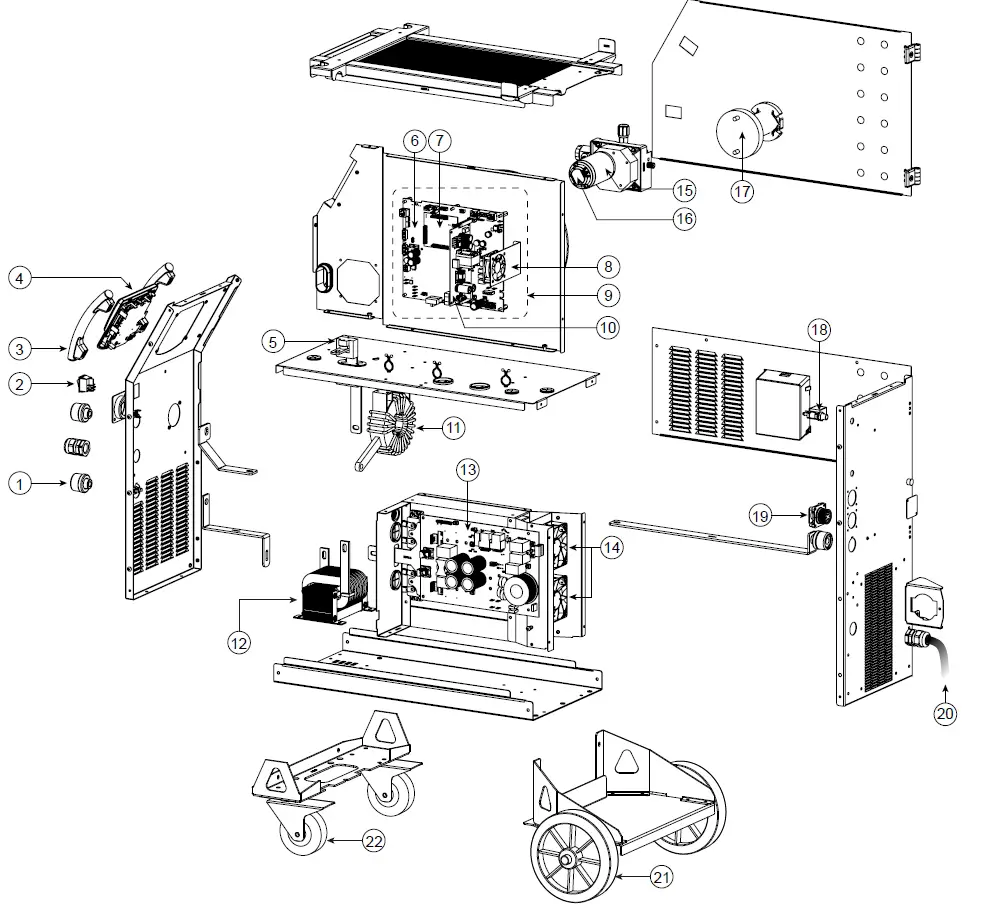
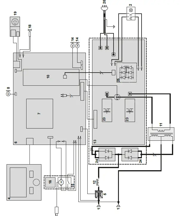
| 400T DUO | ||
| 1 | Female Texas socket | 51478 |
| 2 | Two-pole switch | 52472 |
| 3 | Plastic handle | 56047 |
| 4 | HMI | E0123C |
| 5 | Current sensor | 64463 |
| 6 | Primary board | E0125C |
| 7 | Control board | E0124C |
| 8 | Fan 60x60x20 | 51018 |
| 9 | Low-current block | E5047 |
| 10 | Power supply board | E0167 |
| 11 | Transformer | 63556 |
| 12 | Output choke | 63557 |
| 13 | Power board | E0126C |
| 14 | Fan 92x92x38 | 50999 |
| 15 | Feed motor | 51208 |
| 16 | Tachometer board | E0153C |
| 17 | Reel holder | 71613 |
| 18 | Solenoid valve | 70991 |
| 19 | Interconnection adaptation board | E0134C |
| 20 | Mains cable | 21589 |
| 21 | Wheel diameter 200 | 71375 |
| 22 | Castor wheel | 71360 |
| 23 | IGBT module | 52204 |
| 24 | Secondary diode module | 52225 |
| 25 | Diode Bridge Module | 52196 |
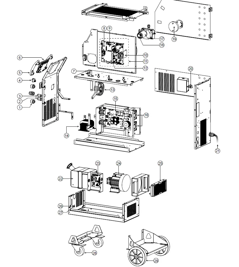
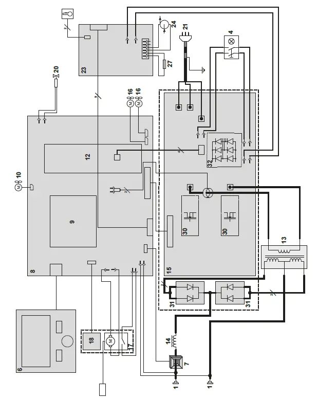
| 400T W | ||
| 1 | Female Texas socket | 51478 |
| 2 | Red coolant connector | 71695 |
| 3 | Blue coolant connector | 71694 |
| 4 | Two-pole switch | 52472 |
| 5 | lastic handle | 56047 |
| 6 | HMI | E0123C |
| 7 | Current sensor | 64463 |
| 8 | Primary board | E0125C |
| 9 | Control board | E0124C |
| 10 | Fan 60x60x20 | 51018 |
| 11 | Low-current block | E5047 |
| 12 | Carte alimentation / Power supply board | E0167 |
| 13 | Transformer | 63556 |
| 14 | Output choke | 63557 |
| 15 | Power board | E0126C |
| 16 | Fan 92x92x38 | 50999 |
| 17 | Feed motor | 51208 |
| 18 | Tachometer board | E0153C |
| 19 | Reel holder | 71613 |
| 20 | Solenoid valve | 70991 |
| 21 | Mains cable | 21589 |
| 22 | Water tank | M0204 |
| 23 | ooling unit board | 97772C |
| 24 | Pump | 55327 |
| 25 | Water radiator | 71996 |
| 26 | Fuse holder | 51387 |
| 27 | Fuse | 51401 |
| 28 | Castor wheel | 71360 |
| 29 | Wheel diameter 200 | 71375 |
| 30 | IGBT module | 52204 |
| 31 | Secondary diode module | 52225 |
| 32 | Diode Bridge Module | 52196 |
CIRCUIT DIAGRAM
TECHNICAL SPECIFICATIONS
| 400T DUO | 400T W | |||||||
| Primary | ||||||||
| Power supply voltage | U1 | 00 V +/- 15% | ||||||
| Mains frequency | 50 / 60 Hz | |||||||
| Number of phases | 3 | |||||||
| Fuse | 32 A | |||||||
| Maximum effective supply current | I1eff | 21 A | ||||||
| Maximum supply current | I1max | 36 A | ||||||
| Mains cable section | 4 x 4 mm² | |||||||
| Maximum active power consumed | 16.6 kW | |||||||
| Idle consumption | 25.32 W | |||||||
| Efficiency at I2max | 87 % | |||||||
| Power factor at I2max | λ | 0.66 | ||||||
| EMC class | A | |||||||
| Secondary | MMA (SMAW) | TIG (GTAW) | MIG-MAG (GMAW-FCAW) | |||||
| No load voltage | U0 (TCO) | 66 V | ||||||
| Nature du courant de soudage | DC | |||||||
| Welding modes | MMA, TIG, MIG-MAG | |||||||
| Minimum welding current | 20 A | 20 A | 15 A | |||||
| Rate current output | I2 | 20 400 A | 20 400 A | 15 400 A | ||||
| Conventional voltage output | U2 | 20.8 36 V | 10.8 26V | 14.75 34 V | ||||
| Duty cycle at 40°C (10 min), Standard EN60974-1.. | Imax | 35 % | 35 % | 35 % | ||||
| * | 60 % | 300 A | 340 A | 300 A | ||||
| 100 % | 280 A | 300 A | 280 A | |||||
| Minimum and maximum diameter of filler wire | Steel | 0.6 1.2 mm | ||||||
| Inox / Stainless | 0.6 1.2 mm | |||||||
| Aluminium | 0.8 1.2 mm | |||||||
| Wire cored | 0.9 1.6 mm | |||||||
| CuA | 0.8 1.0 mm | |||||||
| Torch connector | Euro | |||||||
| Drive roller type | B | |||||||
| Motor speed | 1.5 20 m/min | |||||||
| Motor power | 50 W | |||||||
| Maximum diameter of the supply reel | Ø 300 mm | |||||||
| Maximum weight of the filler wire reel | 18 kg | |||||||
| Maximum gas pressure | 0.5 MPa (5 bar) | |||||||
| Cooling power at 1l/min at 25°C | P1 L/min | – | 0.8 kW | |||||
| Correction factor 40°C | – | 0.58 | ||||||
| Maximum pressure | Pmax | – | 0.53 MPa | |||||
| Functionning temperature | -10°C +40°C | |||||||
| Storage temperature | -20°C +55°C | |||||||
| Protection level | IP23S | |||||||
| Minimum coil insulation class | B | |||||||
| 400T DUO | 400T W | |||||||
| Dimensions (LxWxH) | 90 x 55 x 67 cm | 90 x 55 x 81 cm | ||||||
| Weight | 55 kg | 70 kg | ||||||
* The duty cycles are measured according to standard EN60974-1 à 40°C and on a 10 min cycle. While under intensive use (> to duty cycle) the thermal protection can turn on, in that case, the arc switches off and the indicator switches on. Keep the machine’s power supply on to enable cooling until thermal protection cancellation. The welding power source describes an external drooping characteristic. The power supply shows a flat output pattern.. In some countries, U0 is called TCO.
SYMBOLS
 Warning ! Read the user manual before use.
 User manual symbol
 Undulating current technology based source delivering direct current.
 MMA welding (Manual Metal Arc)
 TIG welding (Tungsten Inert Gas)
 MIG / MAG welding
 Suitable for welding in an environment with an increased risk of electric shock. However this a machine should not placed in such an environment.
 Direct welding current
 Open circuit voltage
 Duty cycle according to standard EN 60974-1 (10 minutes – 40°C).
 Corresponding conventional welding current
- A Amperes
- U2 Conventional voltage in corresponding loads.
- V Volt
- HZ Hertz
 Wire speed
 Meter per minute
 Three-phase power supply 50 or 60Hz
- U1 Assigned voltage
- 11max Maximum rated power supply current (effective value).
- 11eff Maximum effective power supply current.
 Device complies with Europeans directives, The EU declaration of conformity is available on our website (see cover page).
 Equipment in compliance with British requirements. The British Declaration of Conformity is available on our website (see home page).
 Equipment in conformity with Moroccan standards. The declaration C م (CMIM) of conformity is available on our website (see cover page).
- IEC 60974-1 IEC 60974-10 Class A The device is compliant with standard EN60974-1 and EN60971-10 class A device.
- IEC 60974-5 This product is compliant with standard EN 60974-5.
- IEC 60974-2 This product is compliant with standard EN 60974-2.
 This hardware is subject to waste collection according to the European directives 2012/19/EU. Do not throw out in a domestic bin !
 This product should be recycled appropriately
 Warning ! Read the user manual before use.
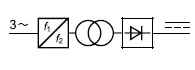 Undulating current technology based source delivering direct current.
 MMA welding (Manual Metal Arc)
 TIG welding (Tungsten Inert Gas)
 MIG / MAG welding
 Suitable for welding in an environment with an increased risk of electric shock. However this a machine should not placed in such an environment.
 Wire speed
 Three-phase power supply 50 or 60Hz
 Device complies with Europeans directives, The EU declaration of conformity is available on our website (see cover page).
 Equipment in compliance with British requirements. The British Declaration of Conformity is available on our website (see home page).
 Equipment in conformity with Moroccan standards. The declaration C م (CMIM) of conformity is available on our website (see cover page).
 This hardware is subject to waste collection according to the European directives 2012/19/EU. Do not throw out in a domestic bin !
 This product should be recycled appropriately
 EAEC Conformity marking (Eurasian Economic Community).
 Temperature information (thermal protection)
 Cooling liquid input.
 Cooling liquid output.
 Gas input
 Gas output
 Fan cooled hardware.
 On (power on)
 Off (power off)
 The safety disconnection device is a combination of the power socket in coordination with the electrical installation. The user has to make sure that the plug can be reached.
 Remote control
 Cooling liquid input.
 Cooling liquid output.
 Gas input
 Gas output
 Fan cooled hardware.
 On (power on)
 The safety disconnection device is a combination of the power socket in coordination with the electrical installation. The user has to make sure that the plug can be reached.
GYS France
Siège social / Headquarter
1, rue de la Croix des Landes – CS 54159
53941 Saint-berthevin Cedex
France
www.gys.fr
+33 2 43 01 23 60
[email protected]
GYS UK
Filiale / Subsidiary
Unit 3
Great Central Way
CV21 3XH – Rugby – Warwickshire
United Kingdom
www.gys-welding.com
+44 1926 338 609
[email protected]
GYS GmbH
Filiale / Niederlassung
Professor-Wieler-Straße 11
52070 Aachen
Deutschland
www.gys-schweissen.com
+49 241 / 189-23-710
[email protected]
GYS Italia
Filiale / Filiale
Vega – Parco Scientifico Tecnologico di
Venezia
Via delle Industrie, 25/4
30175 Marghera – VE
Italia
www.gys-welding.com
+39 041 53 21 565
[email protected]
GYS China
Filiale / 子公司
6666 Songze Road,
Qingpu District
201706 Shanghai
China
www.gys-china.com.cn
+86 6221 4461
[email protected]
GYS Iberica
Filiale / Filial
Avenida Pirineos 31, local 9
28703 San Sebastian de los reyes
España
www.gys-welding.com
+34 917.409.790
[email protected]


 And Mma (smaw) Welding Machine User Manual")
