UBIQUITI UA-Hub
Package Contents
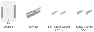
Note: Each UniFi Access component and all third-party accessories are sold separately.
Installation Requirements
- Phillips screwdriver
- Ethernet cables, CAT5e or better
- Copper wire, 18 AWG to 22 AWG
- Drill Kit
- DIN Rail
- Wire Ferrule Terminal (Recommended)
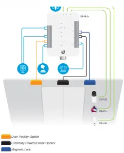
Sample Wiring Topology
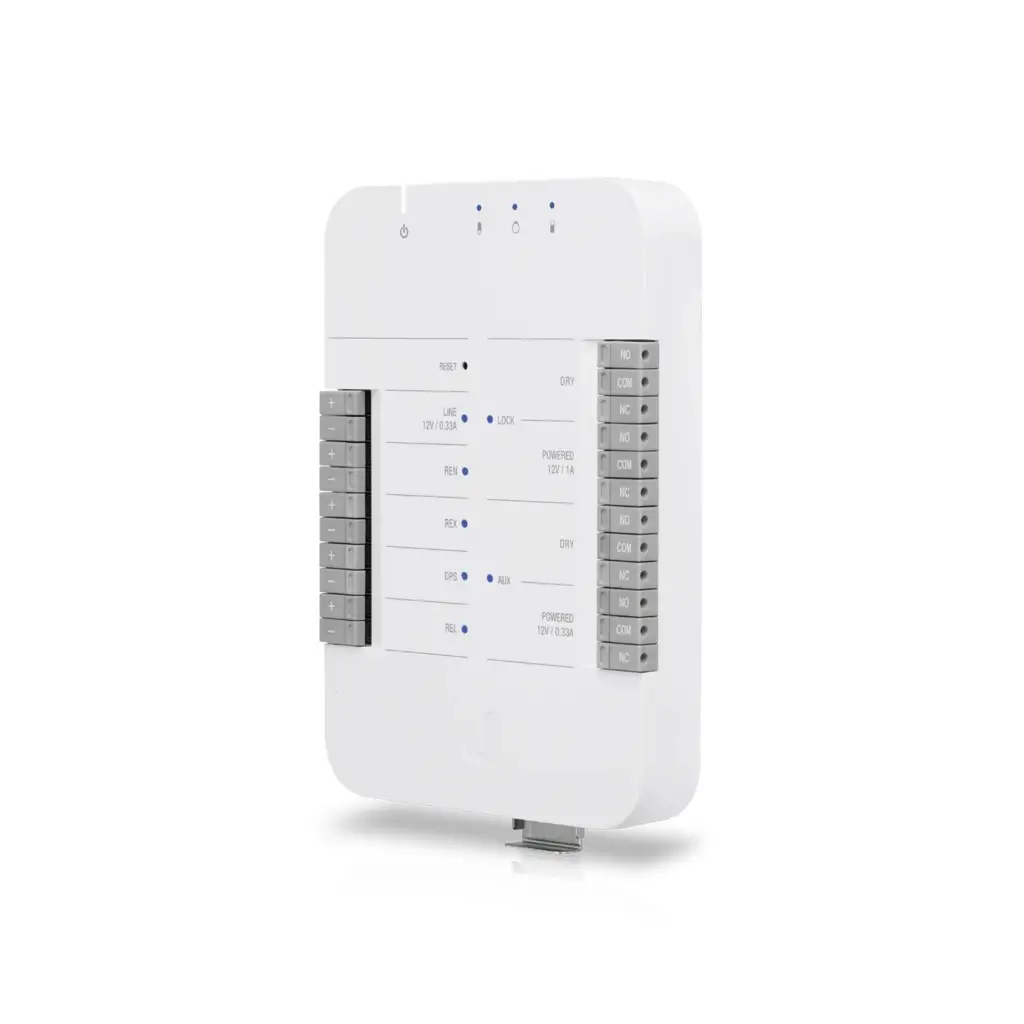
Hardware Overview
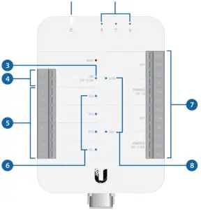
| 1. Power (In) LED | |
| Steady Blue | Adopted/device is ready |
| Steady White | Pending adoption |
| Alternating White/Blue | Upgrading firmware |
| 2. PoE (Out) LEDs | |
| Off | Not connected or no data link |
| Steady Blue | Connected and data link on |
| 3. 12V Line Output LED | |
| Off | Not connected |
| Steady Blue | Effectively connected* |
| 4. 12V Line Output Relays | |
| Line voltage with 12VDC power | |
| 5. Input Relays | |
| REX | Request to exit |
| DPS | Door position switch |
| REL | Remote release |
| 6. Input Relay LEDs | |
| Off | Not connected |
| Steady Blue | Effectively connected* |
| 7. Output Relays | |
| DRY | Output relay with no power |
| POWERED | Output relay with 12VDC |
| 8. Output Relay LEDs | |
| Off | Not connected |
| Steady Blue | Effectively connected* |
* Wires are properly connected to both relays in any of the following sets:
- +/-
- NC/COM
- NO/COM
Default I/O State Matrix
LOCK | |||
Dry | |||
NO | COM | NC | |
| Door Locked Initial State | Opened | Shorted | Shorted |
| Unlocked REN, REX, or REL is shorted; or the reader has granted access | Shorted | Shorted | Opened |
| Powered | |||
NO | COM | NC | |
| Door Locked Initial State | 0V | GND | +12V |
| Unlocked REN, REX, or REL is shorted; or the reader has granted access | +12V | GND | 0V |
AUX | |||
Dry1 | |||
NO | COM | NC | |
| Door Locked Initial State | Opened | Shorted | Shorted |
| Unlocked REN, REX, or REL is shorted; or the reader has granted access | Shorted | Shorted | Opened |
Powered2 | |||
NO | COM | NC | |
1 Example 1: Recommended Setup – Connect AUX DRY to automatic door opener with external power
2 Example 2: Recommended Setup – Connect AUX POWERED to siren (12V / 0.33A / 4W) for door position warning
![]() Note: Specific behaviors can be further configured in UniFi Access Controller.
Note: Specific behaviors can be further configured in UniFi Access Controller.
UA-Hub Wiring
Connecting the UA-Hub to LAN
Ensure the switch port that is connected to the UA-Hub is on the same LAN segment or VLAN as the UniFi Access agent. It must also support PoE+ or PoE++.
Connecting the UA-Pro to the UA-Hub
Use an Ethernet cable to connect the UA-Pro access reader to the UA-Pro PoE port on ![]() the UA-Hub.
the UA-Hub.
Connecting the UA-Lite to the UA-Hub
Use an Ethernet cable to connect the UA-Lite access reader to the UA-Lite PoE port ![]() on the UA-Hub.
on the UA-Hub.
Use an Ethernet cable to connect the G3-Flex camera to the G3-Flex PoE port ![]() on the UA-Hub.
on the UA-Hub.
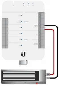
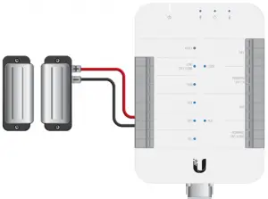
Connecting a Fail-Safe Lock with No External Power Supply
- Connect the Lock Powered (NC) port on the UA-Hub to the (+) on the lock.
- Connect the Lock Powered (COM) port on the UA-Hub to the (-) on the lock.

Fail-safe lock in this diagram refers to magnetic lock or electric bolt.
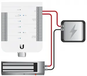
Connecting a Fail-Safe Lock with an External Power Supply
- Connect the Lock DRY (NC) port on the UA-Hub to the (+) on the lock.
- Connect the (-) on the lock to the (-) on the external power supply.
- Connect the Lock DRY (COM) port on the UA-Hub to the (+) on the external power supply.

Connecting a Push Button
1. Connect NO on the push button to REL (+) on the UA-Hub.
2. Connect COM on the push button to REL (-) on the UA-Hub.
![]() Note: REL, REX, and REN all work the same way with push buttons.
Note: REL, REX, and REN all work the same way with push buttons.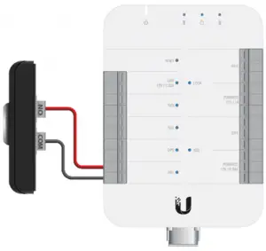
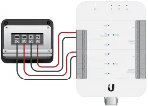
Connecting a Motion Sensor
- Connect NO on the motion sensor to REX (+) on the UA-Hub.
- Connect COM on the motion sensor to REX (-) on the UA-Hub.
- Connect V+ on the motion sensor to Line 12V (+) on the UA-Hub.
- Connect V- on the motion sensor to Line 12V (-) on the UA-Hub.

Connecting a Siren
- Connect AUX Powered (NO) on the UA-Hub to the (+) on the siren.
- Connect AUX Powered (COM) on the UA-Hub to the (-) on the siren.
![]() Note: AUX powered output is 12VDC up to 0.33A.
Note: AUX powered output is 12VDC up to 0.33A.
The diagram below is an example; please consult the manual for your specific siren.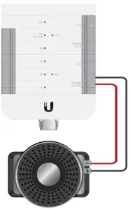
Connecting a Door Position Switch (Door Sensor)
- Connect NC on the door position switch to the DPS (+) on the UA-Hub.
- Connect COM on the door position switch to the DPS (-) on the UA-Hub.

Connecting an Automatic Door Opener with an External Power Supply
Please consult the manual for your specific automatic door opener. Use the AUX relays for the automatic door opener connection.
Connect the Lock Powered NO and COM ports on the UA-Hub to the NO and COM ports on the fail-secure lock, respectively.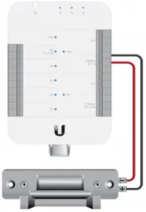
Fail-secure lock in this diagram refers to electric strike.
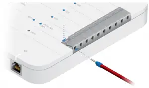
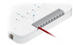
Connecting Wire to Terminal Block
1.
2.
3.
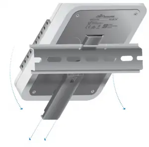
Hardware Installation
DIN Rail
Peripherals
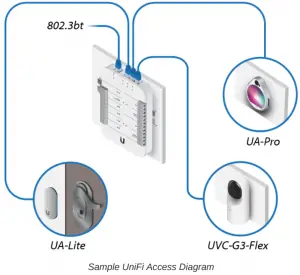
![]() Note: The UA-Hub also features an additional PoE port for the UVC G3FLEX camera (optional).
Note: The UA-Hub also features an additional PoE port for the UVC G3FLEX camera (optional).
Locks
Install each lock in its respective location. Each lock can be installed and connected to the UA-Hub in one of two ways:
- Dry connections
- Powered connections, 12VDC
Dry locks do not require power from the UA-Hub and are generally accompanied by their own external power or power adapter.
Powered locks receive 12VDC power from the UA-Hub.
UniFi Access Controller
Setup UniFi Access on your UDM-Pro
Specifications
UA-Hub | |
| Dimensions | 190 x 126 x 33 mm (7.48 x 4.96 x 1.29″) |
| Weight | 457 g (16.12 oz) |
| Enclosure Characteristics | Plastic Enclosure with Metal Mount Plate |
| Mounting Options | DIN Rail |
| Networking Interface | (4) 1 Gbps Ethernet |
| Max. Power Consumption | 40W |
| Power Method | 802.3bt |
| Powered Relay Lock Aux Line | Output 12VDC, up to 1A Output 12VDC, up to 0.33A Output 12VDC, up to 0.33A |
| LEDs | (1) System, (3) PoE Out, (4) Input (2) Output Relays, (1) 12VDC Out |
| Buttons | Terminal Blocks, Reset |
| Operating Humidity | 5 to 90% Non-Condensing |
| Operating Temperature | 0 to 40° C (32 to 104° F) |
| Certifications | CE, FCC, IC |
Specifications for Recommended Wiring
| Typical Installation (Shielded) | |
| DC Power Input | Belden 8750 18 AWG 2 Conductor (30.5 m / 100 ft) |
| Door Position Switch | Belden 8750 18 AWG 2 conductor (152.5 m / 500 ft) |
| Request to Exit | Belden 8750 18 AWG (up to 152.5 m / 500 ft) |
| Lock Relay Output | Belden 8750 18 AWG (up to 152.5 m / 500 ft) |
| Auxiliary Relay Output | Belden 8750 18 AWG (up to 152.5 m / 500 ft) |
Wiring Gauge Requirements (AWG)* | ||||
| Total Length to Device | Output Load Current @ 12VDC | |||
100mA | 250mA | 500mA | 1A | |
6.1 m (20 ft) | 22 | 22 | 22 | 18 |
15.2 m (50 ft) | 22 | 22 | 22 | 18 |
30.5 m (100 ft) | 22 | 22 | 18 | 18 |
Use CTE cable connectors that comply with local electrical codes.
Safety Notices
- Read, follow, and keep these instructions.
- Heed all warnings.
- Only use attachments/accessories specified by the manufacturer.
![]() WARNING: Do not use this product in location that can be submerged by water.
WARNING: Do not use this product in location that can be submerged by water.
![]() WARNING: Avoid using this product during an electrical storm. There may be a remote risk of electric shock from lightning.
WARNING: Avoid using this product during an electrical storm. There may be a remote risk of electric shock from lightning.
- Compliance is required with respect to voltage, frequency, and current requirements indicated on the manufacturer’s label. Connection to a different power source than those specified may result in improper operation, damage to the equipment or pose a fire hazard if the limitations are not followed.
- There are no operator serviceable parts inside this equipment. Service should be provided only by a qualified service technician.
- The equipment requires the use of the ground wire as a part of the safety certification, modification or misuse can provide a shock hazard that can result in serious injury or death.
Limited Warranty
The limited warranty requires the use of arbitration to resolve disputes on an individual basis, and, where applicable, specify arbitration instead of jury trials or class actions.
Compliance
FCC
Changes or modifications not expressly approved by the party responsible for compliance could void the user’s authority to operate the equipment. This device complies with Part 15 of the FCC Rules. Operation is subject to the following two conditions.
- This device may not cause harmful interference, and
- This device must accept any interference received, including interference that may cause undesired operation.
This equipment has been tested and found to comply with the limits for a Class A digital device, pursuant to Part 15 of the FCC Rules. These limits are designed to provide reasonable protection against harmful interference when the equipment is operated in a commercial environment. This equipment generates, uses, and can radiate radio frequency energy and, if not installed and used in accordance with the instruction manual, may cause harmful interference to radio communications. Operations of this equipment in a residential area is likely to cause harmful interference in which case the user will be required to correct the interference at his own expense.
ISED Canada
CAN ICES-3(A)/NMB-3(A)
Australia and New Zealand
![]() Warning: This equipment is compliant with Class A of CISPR 32. In a residential environment this equipment may cause radio interference.
Warning: This equipment is compliant with Class A of CISPR 32. In a residential environment this equipment may cause radio interference.
CE Marking

Online Resources


© 2021 Ubiquiti Inc. All rights reserved.


