Hangzhou Roombanker Technology Co., Ltd A Dusun Company
Product Specification
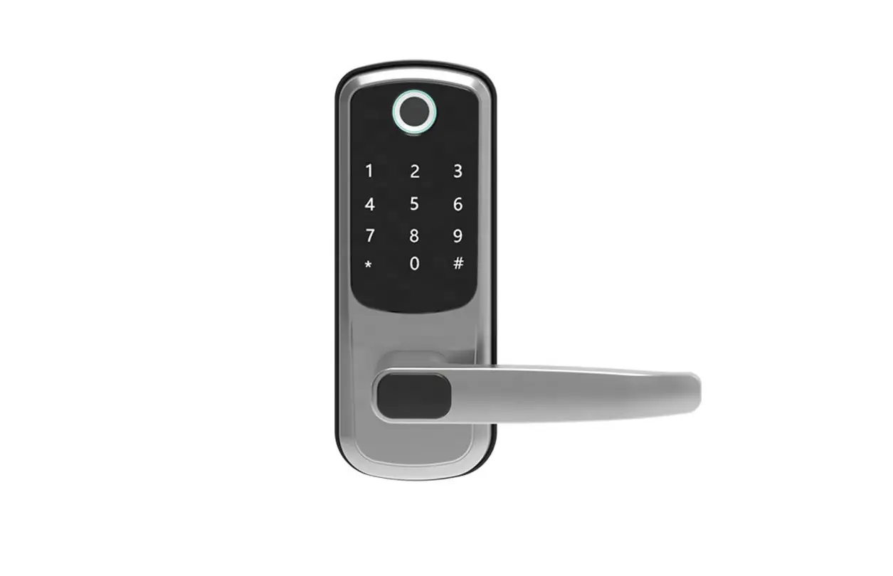
Product Name: US Deadbolt lock
Model Name: DSL-090-1
Revision History
| Specification | Sect. | Update Description | By | |
| Rev | Date | |||
| 1.0 | 2023-03-08 | New version release | Cuihao | |
| 1.1 | 2023-03-09 | Add product label description | Cuihao | |
| 1.2 | 2023-03-15 | Add how to enter programming mode description | Cuihao | |
Approvals
| Organization | Name | Title | Date |
1 Introduction
1.1 Purpose& Description
DSL-090-1 powered by Roombanker is convenient to protect your home safety. It’s easy to install, easy to use. It supports four unlocking methods, such as card, fingerprint, password and mechanical key. This product can be applied to family, apartment and hotel scenes.
This guide will help you to get through the initial setup to installation.
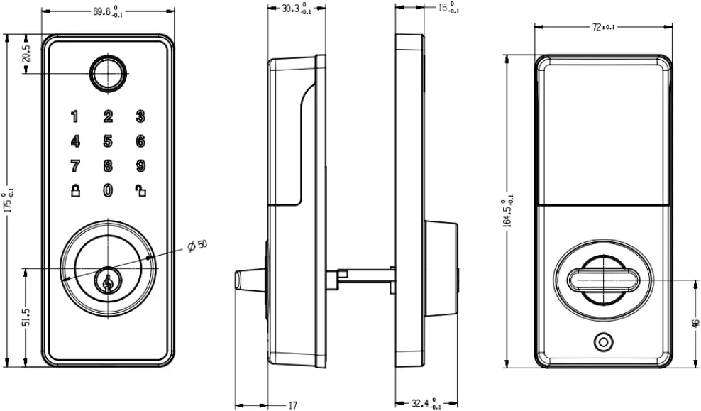
2 Mechanical Requirement
2.1 Drawing
2.2 Components List
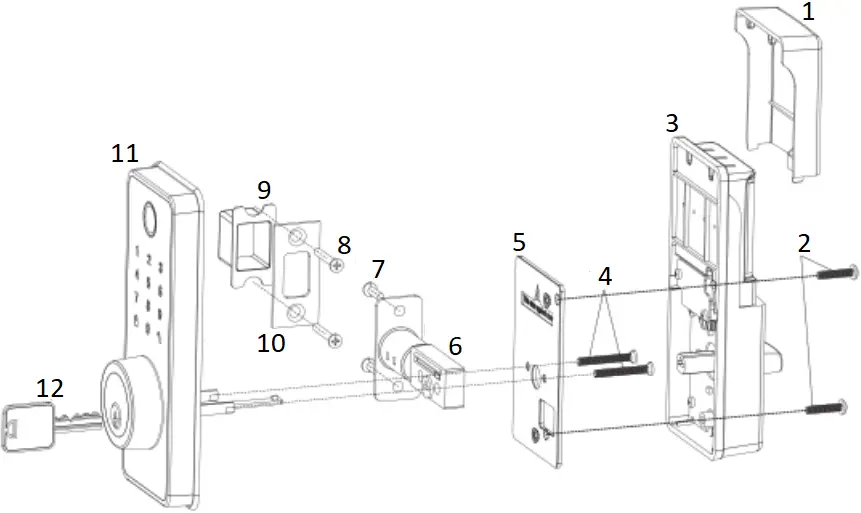
- Battery Cover (F)
- Interior Assembly Screws (I)
- Interior Assembly (C)
- Mounting Plate Screws (H)
- Mounting Plate (D)
- Latch (A)
- Latch Screws (G)
- Strike Screws (G)
- Buckle Box (J)
- Strike Plate (E)
- Exterior Assembly (B)
- Backup key (K)
Parts List
| (A) Latch x1
| (B) Exterior Assembly x1
| (C) Interior Assembly x1
| (D) Mounting Plate x1
|
| (E) Strike Plate x1
| (F) Battery Cover x1
| (G) 3/4″ (19mm) Strike/Latch Screws x4
| (H) 1-5/32″ (33mm) Mounting Plate Screws x2
|
| (I) 3/4″ (19mm) Interior Assembly Screws x2
| (J) Buckle Box x1
| (K) Backup key x2 IC Card x2 | (L) IC Card x2
|


3 Specification
Performance | |
| 2.4G hz wireless protocol |
|
| Operation temperature | -25~55℃ |
| Storage temperature | -25~60℃ |
| Operation humidity | RH ≤85% |
| Power supply | DC 6V, AA*4 |
| Sleep current with 2.4G on | <100uA |
4 Installation Guide
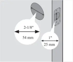
Step 1 Prepare the door and check dimensions
If you need to drill a new door, use the supplied template and the complete door drilling instructions.
A
Measure to confirm that the hole in the door is 2-1/8″ (54mm).
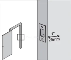
Measure to confirm that the hole in the door edge is 1″ (25mm).
B
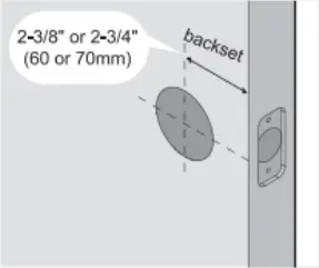
Measure to confirm that the backset is either 2-3/8″ or 2-3/4″ (60 or 70mm)
C
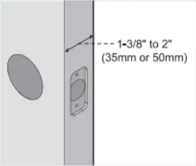
Measure to confirm that the door is 1-3/8″ to 2″ (35 mm or 50mm) thick.
D
Make sure the hole in door frame is dried a minimum of 1″ (25mm) deep.
Template
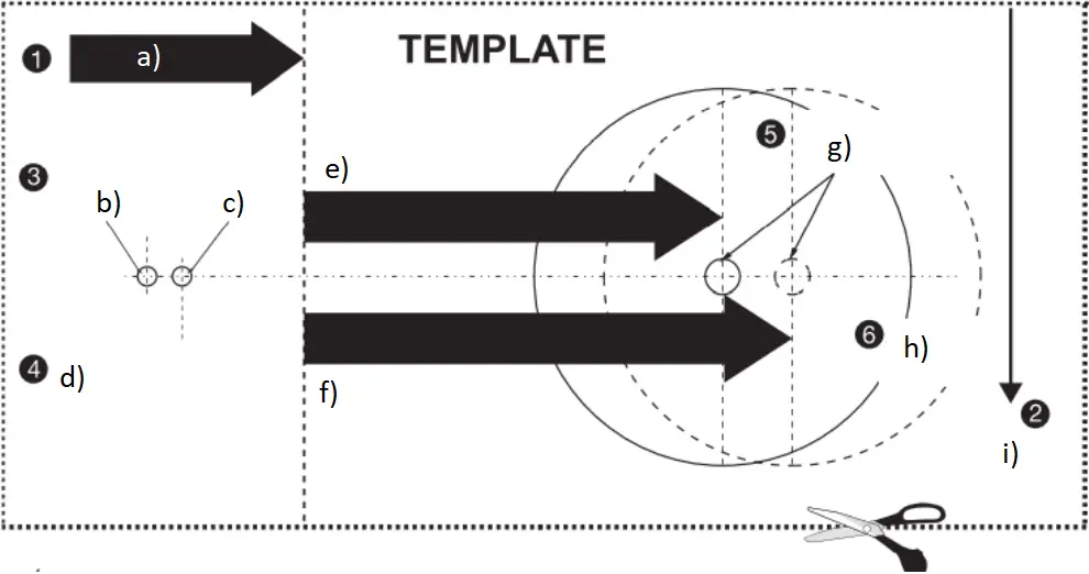
a) FOLD HERE ON DOOR EDGE
b) MARK FOR 1-3/4″ (45mm) DOOR
c) MARK FOR 1-3/8″ 135mm) DOOR
d) THEN DRILL 1″ (25mm) HOLE IN CENTER DOOR OF EDGE 2″ (50mm) IN DEPTH
e) FOR INSTALLING ENTRY LOCK AND DEADBOLTS
f) IMPORTANT! PLACE TEMPLATE ON HIGH EDGE OF DOOR BEVEL
g) MARK CENTER OF HOLE ON DOOR FACE
h) DRILL 2-1/8″ (54mm) HOLE
i) PLACE TOP 36″ (915mm) ABOVE FLOOR
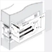
1. TEMPLATE
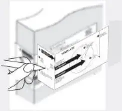
1-a. Cut out template printed in this manual.

1-b. Fold template and place on door 36″ (915mm) from the ground as marked.
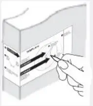
2. MARK THE DOOR FOR DRILLING
2-a. Mark center hole on door edge through guidance on template for 1″ (25mm) latch bolt.
2-b. Mark center hole on door face through guidance on template for 2-3/8″ (60mm) or 2-3/4″ (70mm) backset.
3-a. Drill 2-1/8″ (54mm) hole through door panel as marked for lock set.
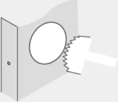
3-b. Drill 1″ (25mm) hole in center of door edge for Deadbolt Latch Assembly.
3-c. Insert Deadbolt Latch Assembly in hole keeping it parallel to face of door.
Mark outline and remove latch.
3-d. Chisel 5/32″(4mm) deep or until latch face is flush with door edge.
4-a. Mark center hole on edge of jamb even with the center of the Latch Bolt on door edge.
4-b. Drill 1″ (25 mm) hole 1-3/16″ (30 mm) deep in door Jamb on center mark.
4-c. Outline outside edges of Stake Plate.
4-d. Chisel 5/32″ (4 mm) deep for Strike Plate or until it is flush with door surface.

4-e. Install Strike Plate using two 3/4″ (19 mm) screws provided.
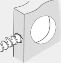
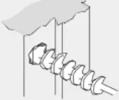
Step 2 Install the latch and strike
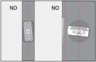
A Determine backset A and adjust the latch
Hold the latch in front of the door hole, with the latch face flush against the door edge. Is the slotted hole centered in the door hole?
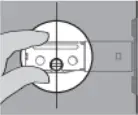
YES
No adjustment is required.
Proceed to next step.
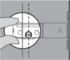
NO
Slotted hole is NOT centered.
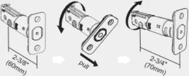
Twist the latch and adjust the boll length.
(Make sure the latch bolt is retracted.)
B
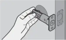
Install the latch
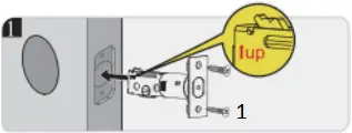
- Latch Screws (G)
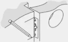
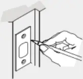
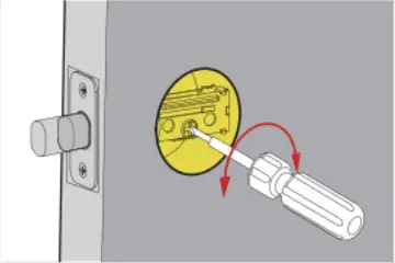
C Use a screwdriver to test If deadbolt works smoothly.
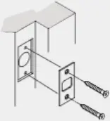
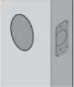
D Install strike on the door frame.
![]() IMPORTANT:
IMPORTANT:
Make sure the hole in door frame is drilled a minimum of 1″ (25mm) deep.
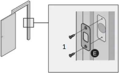
- Strike Screws (G) x2
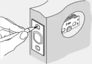
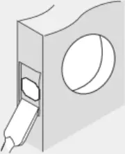
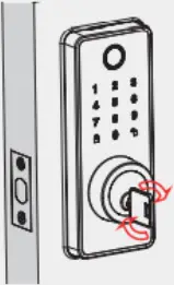
Step 3 Install the exterior assembly
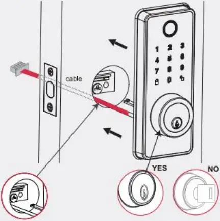
Route the cable through the door below the bolt and push the keypad onto the door.
![]() IMPORTANT:
IMPORTANT:
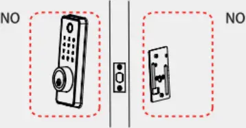
The key must be pulled out when installing.
Step 4 Install the interior assembly
1 Take off the mounting plate (D).
![]() IMPORTANT:
IMPORTANT:
Do not bad batteries until lock is completely installed.
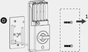
- Loosen the 2 screws.
2 Route cable through the bottom of mounting plate.
3 Tighten screws.
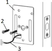
- Mounting plate (D)
- Mounting plate Screws (H)
- Cable
Note: Please support exterior assembly during mounting plate installation.
4 Ensure tight cable connection.
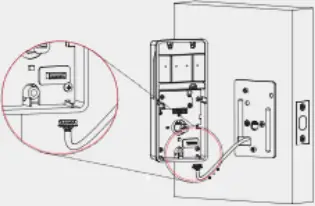
The smooth side of the plug should be at the bottom.
5 Tighten screws.

- Interior assembly screws (I)
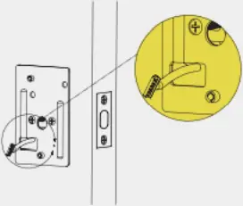
6 Insert key and test latch.
If latch does not extend or retract smoothly, adjust mounting plate screws.
If the keypad and mounting plate are deflected, loose mounting plate screws and adjust.
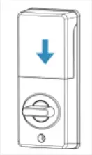
Step 5 Install the batteries and perform the door handing process
1 While the door is OPEN and UNLOCKED, load 4 AA batteries into the battery compartment.
![]() IMPORTANT:
IMPORTANT:
Do not use rechargeable batteries or non-alkaline batteries.
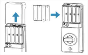
The batteries are not included.
2 Perform the door handing process.
a. Press ![]() , the latch bolt extends by itself.
, the latch bolt extends by itself.
b. Enter preset programming code: 600900. then press ![]() , the latch bolt retracts by itself.
, the latch bolt retracts by itself.
![]() If the latch bolt cannot extend or retract smoothly, check the latch and re-install the lock.
If the latch bolt cannot extend or retract smoothly, check the latch and re-install the lock.
Success Failure
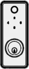
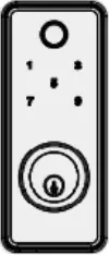
5 Operation Instructions
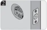
Exterior Assembly
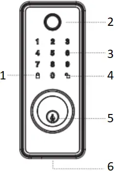
- Lock and Clear
- Fingerprint
- Keypad
- Unlock / Programming
- Keyhole
- Micro-usb
Interior Assembly
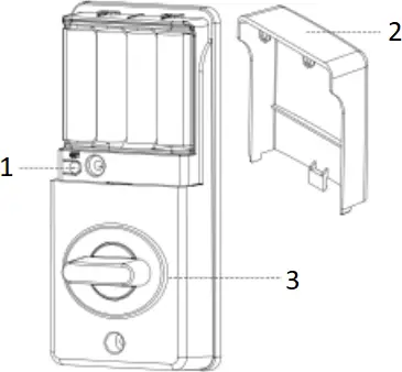
- SET Button
- Battery Door
- Turn Knob
Note: Micro-usb interface is used for emergency power
| Item | Capacity | Permissions |
| Administrator password | 1 |
|
| Password | 50 | Unlock |
| Fingerprint | 99 | Unlock |
| Card | 50 | Unlock |
Press unlock button to enter programming mode, then input administrator password(600900) according to voice tips, then press unlock button again.
Locking and unlocking
TO UNLOCK THE LOCK
- Using Keypad: Enter a valid password (Default password is:600900) and press unlock key.
- Using valid Finger user
- Using valid Card
- Using mechanical key
5.1 Set administrator password
Factory default Programming Code = 600900
In programming mode, there is a voice prompt:
“Password management press 1 “,
“Fingerprint management press 2”,
“IC card management press 3”,
“Modify the administrator password press 4”,
“Set automatic lock time press 5”,
5.2 Password programming
Press 1 to get into programming mode.
Voice navigation “Add password user press1”,
“Delete password user press2”,
“Clear passwords user press 3”,
“Return press lock key”
5.2.1 Add password
Press 1 to add password.
Voice navigation “Please enter the user number “,
Enter user ID number (1~210 digits), press the unlock key, the input 6~9 digits for a new password, press unlock key. Input again the same numbers and press unlock key, Voice prompt “Add success”.
5.2.2 Delete password
Press 2 to delete password.
Voice navigation “Enter user number want to delete”
Enter user ID number press unlock key, Enter the user ID number again and press the unlock key, the voice prompt ” User number “XXX” delete success “.
5.2.3 Clear password
Press 3 to clears the password.
Voice navigation “Please enter administrator password”, input the correct administrator password and press the unlock key,
Voice prompt “Password user cleared”.
5.3 Fingerprint management
Press 2 to get into fingerprint management.
Voice navigation “Add fingerprint user press 1”,
“Delete fingerprint user press 2”,
“Clear fingerprint user press 3”,
“Return press lock key”
5.3.1 Add fingerprint
Press 1 to add fingerprint, Voice navigation ” Please enter the user number ”
Enter user ID number (1~210 digits).
Voice navigation “Please press finger “,”Please press finger again”(Finger should be flat on the sensor), follow the voice navigation press the finger 4 times.
5.3.2 Delete fingerprint
Press 2 to delete the fingerprint.
Voice navigation “Enter User number want to delete”
“Enter User number want to delete again”. Every time after user number press unlock key
“User number “XXX” delete success”.
5.3.3 Clear fingerprint
Press 3 to empty the fingerprint.
Voice navigation “Please enter administrator password”. Voice navigation “Fingerprint user cleared”
5.4 Card Management
Add IC card user press 1
Delete IC card user press 2
Clear IC card user press 3
Return press lock key
5.4.1 Add a user card
Voice navigation “Please enter user number”, enter card ID number (1~210 digits) and press unlock key.
“Please put IC card”,
“Add success”.
5.4.2 Delete the user card
Voice navigation “Enter user number want to delete” then press unlock key,
“Enter user number want to delete again” then press unlock key,
“User number “XXX” delete success”.
5.4.3 Clear the user card
Voice navigation “Please enter administrator password”, press unlock key
“IC card user cleared”.
5.5 Modify management password
Press 4 to get into changes the management password.
Voice navigation “Enter new management password”,
Enter 6~9 digits for a new management password, press the unlock key and enter the same number again, press unlock key, voice prompt “Password changed”.
5.6 Set the automatic lock time
Factory default is 5 Seconds, set the range(3~30)Seconds.
Press 0 turn off the automatic lock function.
Press 5 to set automatic lock time. Voice navigation ” Set up automatic lock time”
The input digital “(3~30)” will be the automatic lock time
5.7 Restore factory Settings
Press “set” button more than 5 seconds.
Voice prompt: initialization successful, Welcome use the lock.
After setting, the default management password is 600900
The user password is 600900
The user password is 1 Group,
The fingerprint is empty and the others are factory default
5.8 Turn on or off voice prompt
Touching to light up the password tray, press three times unlock key to turn on or off voice prompt.
5.9 System locking
When opening the lock continuous input 5 times incorrect user password, or wrong fingerprint, or incorrect user card,voice navigation “Failure and lock the system”.
6 Voice Tips
① Operation:Press “set” button once to enter setup mode
Voice navigation: “Please enter administrator password”
② Operation:When entering the same user ID
Voice navigation: “The user exist”
③ Operation:Power on
Voice navigation: “Welcome use the lock”
④ Operation:No operation for 15 seconds under setup mode
Voice navigation: “Operation time out,exit setup mode”
⑤ Operation:Input 5 times incorrect user password/wrong fingerprint/invalid IC card
Voice navigation: “Failure and lock the system”
⑥ Operation:Input incorrect user password/wrong fingerprint/invalid IC card once
Voice navigation: “Verification failed”
⑦ Operation:Enter invalid user ID
Voice navigation: Input error
⑧ Operation:When adding password user more than 50 groups
Voice navigation: “Password user is full”
⑨ Operation:When adding Fingerprint user more than 99 groups
Voice navigation: “Fingerprint user is full”
⑩ Operation:When adding IC card user more than 50 groups
Voice navigation: “IC card user is full”
7 System Alerts
| Alert | Possible cause | Solution |
| beep and voice prompt “Close Lock failed” | Fail to lock | Re-lock the door |
| No voice prompt | Voice prompt off | Press unlock button three times |
| The screen flashes 5 times + voice prompt “Low power, please replace the battery in time” | Low battery | Replace batteries |
| The screen flashes 5 times, + voice prompt “Low power, please replace the battery in time”, and can not unlock | Super low battery | Replace batteries |
8 Remote administration
DSL-090-1 supports remote administration, administrator can remotely add or delete user cards and passwords. When users open the lock, DSL-090-1 will upload the unlock record to the administration system.
9 Packaging
| Box size | 192mm(L)*142mm(W)*112mm(H) |
| Gross weight/Per Box | 1.43Kg |
| Quantity per carton | 12 PCS |
| Carton size | 380mm(L)*423mm(W)*230mm(H) |
| Gross weight/Per Carton | 17.16Kg |
DSL-090-1 needs 2 QR codes which contains the device mac address, one QR code nedds to be stuck to the back of the lock, and the other one needs to be stuck to the inside of battery cover, as shown below.
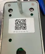
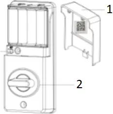
- Battery door
- Turn knob
Floor 8, Building A, Wantong Center
Tel: 86-571-86769027/8 8810480 Hangzhou, China
Website: www.dusuniot. www.dusunremotes.com www.dusunlock.com
FCC Statement
1. This device complies with Part 15 of the FCC Rules. Operation is subject to the following two conditions:
(1) This device may not cause harmful interference.
(2) This device must accept any interference received, including interference that may cause undesired operation.
2. Changes or modifications not expressly approved by the party responsible for compliance could void the user’s authority to operate the equipment.
NOTE:
This equipment has been tested and found to comply with the limits for a Class B digital device, pursuant to Part 15 of the FCC Rules.
These limits are designed to provide reasonable protection against harmful interference in a residential installation.
This equipment generates uses and can radiate radio frequency energy and, if not installed and used in accordance with the instructions, may cause harmful interference to radio communications. However, there is no guarantee that interference will not occur in a particular installation. If this equipment does cause harmful interference to radio or television reception, which can be determined by turning the equipment off and on, the user is encouraged to try to correct the interference by one or more of the following measures:
Reorient or relocate the receiving antenna.
Increase the separation between the equipment and receiver.
Connect the equipment into an outlet on a circuit different from that to which the receiver is connected.
Consult the dealer or an experienced radio/TV technician for help.
To comply with RF exposure requirements, a minimum separation distance of 20cm must be maintained between the users body and the device, including the antenna.


