NOVUS Submersible Hydrostatic Level Transmitter
INTRODUCTION
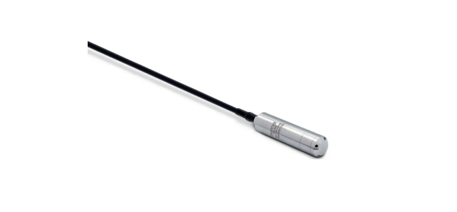
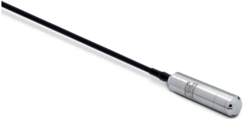
Submersible Hydrostatic Level Transmitter is designed for continuous monitoring of liquid level in water wells, reservoirs, tanks, boreholes, rivers and other liquids. The submersible unit will detect the hydrostatic pressure at the bottom of the liquid and transmit a proportional current signal to the water column for system instrumentation.
The highly stable 316L stainless steel diaphragm sensor is compatible with raw or chlorinated water and most semi-aggressive liquids and oils.
Several level measurement ranges are available and allow a wide range of applications, such as installation on local or remote panels and use with data loggers or PCLs.
TECHNICAL SPECIFICATION
| Pressure Range | 1 … 100 m WC (1, 1.6, 2.5, 4, 6, 10, 16, 25, 40, 60 and 100 m WC) |
| Cable Length | 5 … 120 m (5, 10, 15, 20, 30, 40, 50, 80 and 120 m) |
| Sensor | Piezoresistive diaphragm |
| Analog Output | 4-20 mA |
| Accuracy | 0.5 % F.S. @25°C |
| Cable | Pur (polyurethane) 2x conductor, shield and ventilation tube |
| Temperature Compensation | 0 m ~ 10 m WC: 0 to ~60 °C |
| 10 m ~ 200 m WC: -10 to ~70 °C | |
| Zero temp. coefficient | ± 1.5 % F.S. (within temperature compensation) |
| Span temp. coefficient | ± 1.5 % F.S. (within temperature compensation) |
| Mechanical Vibration | 20 g (20~500 HZ) |
| Mechanical Shock | 20 g (11 ms) |
| Insulation | 100 MΩ / 250 VDC |
| Response Time | ≤ 1 ms (Up to 90 % F.S.) |
| Long Term Stability | ±0.2 % F.S./year |
| Operating Temperature | 0 to 60 °C If measuring range < 4 m WC |
| -10 to 70 °C If measuring range ≥ 4 m WC | |
| Storage Temperature | -40 to 125 °C |
| Power Supply | Loop-powered 4-20 mA (12 ~ 36 Vcc) |
| Housing Material | Sensor: SS 316L Housing: SS 304 Protective cover: SS 304 |
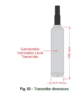
| Dimensions | Height: 105 mm Diameter: 26.5 mm |
| Level of Protection | IP68 |
| Overpressure Limit | <=6 m WC: 3x F.S. >=10 m WC: 2x F.S. |
| Electrical Protection | Reverse polarity and current limiter |
| Certification | CE, UKCA, RoHS |
| Warranty | 1 year |
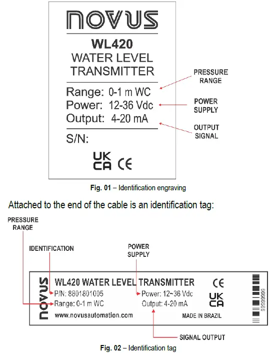
IDENTIFICATION
The Submersible Hydrostatic Level Transmitter has the following identification engraving on the sensor body:
And it is supplied in the following models:
| MODEL | PRESSURE RANGE | OVER- PRESSURE | BURTS PRESSURE | CABLE |
| WL420-1M-L5 | 1 m WC | 300 % F.S. | 600 % F.S. | 5 m |
| WL420-1M-L15 | 1 m WC | 300 % F.S. | 600 % F.S. | 15 m |
| WL420-1.6M-L5 | 1.6 m WC | 300 % F.S. | 600 % F.S. | 5 m |
| WL420-1.6M-L15 | 1.6 m WC | 300 % F.S. | 600 % F.S. | 15 m |
| WL420-2.5M-L5 | 2.5 m WC | 300 % F.S. | 600 % F.S. | 5 m |
| WL420-2.5M-L15 | 2.5 m WC | 300 % F.S. | 600 % F.S. | 15 m |
| WL420-4M-L10 | 4 m WC | 300 % F.S. | 600 % F.S. | 10 m |
| WL420-4M-L15 | 4 m WC | 300 % F.S. | 600 % F.S. | 15 m |
| WL420-6M-L10 | 6 m WC | 300 % F.S. | 600 % F.S. | 10 m |
| WL420-6M-L15 | 6 m WC | 300 % F.S. | 600 % F.S. | 15 m |
| WL420-10M-L15 | 10 m WC | 200 % F.S. | 500 % F.S. | 15 m |
| WL420-10M-L20 | 10 m WC | 200 % F.S. | 500 % F.S. | 20 m |
| WL420-16M-L20 | 16 m WC | 200 % F.S. | 500 % F.S. | 20 m |
| WL420-16M-L30 | 16 m WC | 200 % F.S. | 500 % F.S. | 30 m |
| WL420-25M-L40 | 25 m WC | 200 % F.S. | 500 % F.S. | 40 m |
| WL420-40M-L50 | 40 m WC | 200 % F.S. | 500 % F.S. | 50 m |
| WL420-60M-L80 | 60 m WC | 200 % F.S. | 500 % F.S. | 80 m |
| WL420-100M-L120 | 100 m WC | 200 % F.S. | 500 % F.S. | 120 m |
MECHANICAL INSTALLATION
The Submersible Hydrostatic Level Transmitter transmitter is suitable to be installed in places with static pressure levels such as liquid tanks, sewers, swimming pools, boreholes, rivers, sea and lakes.
DIMENSIONS
Fig. 03 shows the device dimensions:
ELECTRICAL INSTALLATION
Fig. 04 shows the transmitter cable connections:
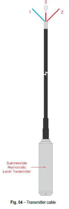
Table 03 shows the composition of the cable:
| Function | Color | |
| 1 | Output current | Blue wire |
| 2 | Power supply | Red wire |
| 3 | Vent tube | Red tube |
Table 03 – Cable composition
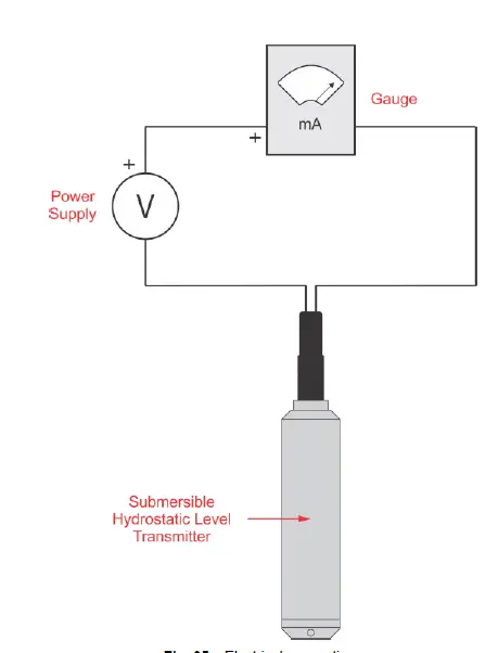
Fig. 05 shows the electrical connections required for installing the device:
RECOMMENDATIONS FOR INSTALLATION
- During installation, do not obstruct the connection cable vent.
- Input signal conductors must run through the system floor plan separately from the output and supply conductors. If it is possible, in grounded conduits.
- The instruments must be powered from the instrumentation power supply circuit.
- In control and monitoring applications is essential to consider what can happen when any part of the system fails.
- It is recommended the use of suppressors in contact coils, solenoids and any inductive load.
INSTALLATION INSTRUCTIONS
- STILL WATER INSTALLATION

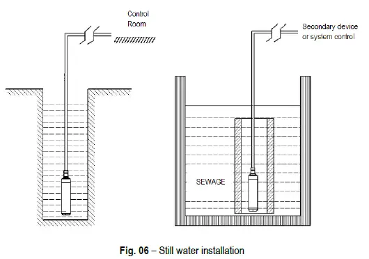
- When measuring the level of stationaty fluid in an open container, place the Submersible Hydrostatic Level Transmitter vertically into the bottom of the container.
- When the average viscosity is relatively high (such as in a sewage pool), you can install a bracket to ensure that the transmitter is positioned at the bottom of the container.
- When doing an outdoor installation, the junction box of the transmitter must be placed in a ventilated, dry place to avoid direct exposure to light and rain, which could cause the junction box temperature to be too high or allow water to enter and consequent damage to the internal circuit board.
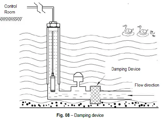
MOVING WATER INSTALLATION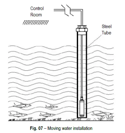
- When there is a lot of variation when measuring the level in running water, you can insert a steel tube with an internal diameter of about 50 cm into the channel. In addition, several holes of about Φ5 in diameter should be made in the submerged part of the tube, on the side opposite the direction of flow. This helps to avoid oscillations in the level measurement.

- When the water channel is very uneven or there is a lot of sediment in the bottom, you can install a damping device to filter it out. This eliminates the adverse effects of dynamic pressure and ensures measurement accuracy.
- It is recommended to install lightning protection devices where the Submersible Hydrostatic Level Transmitter will be installed. It is also recommended that the device and power supply be properly grounded to reduce lightning damage to the transmitter.
WARRANTY
Warranty conditions are available on our website www.novusautomation.com/warranty.


