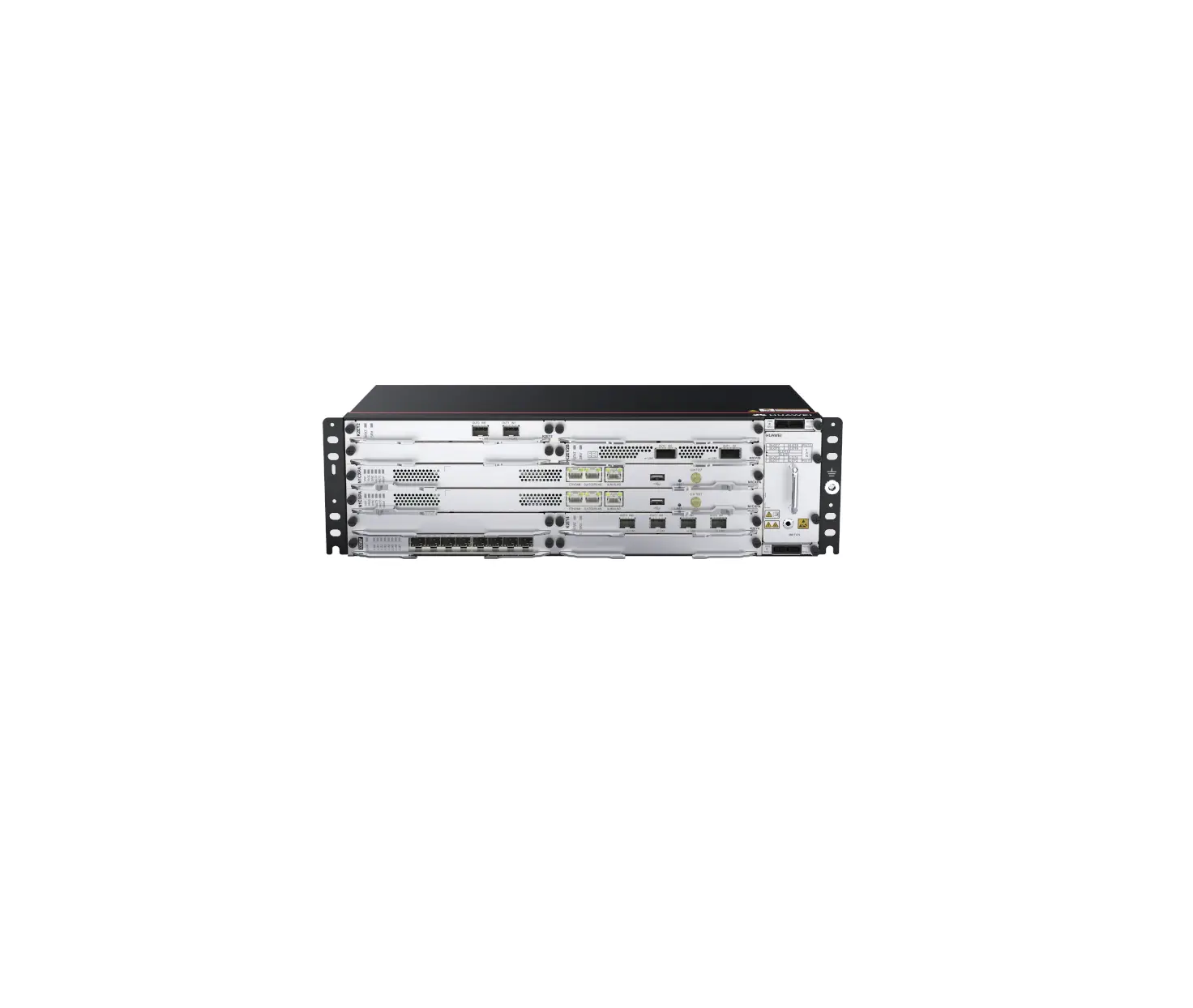
HUAWEI ATN 980D IEC 19-inch and ETSI 21-inch Cabinet
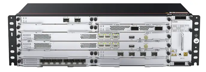
Device Overview
Packing list
- Insulation tape
- Label cable tie
- Signal cable label
- Corrugated pipe
- ESD wrist strap
- Panel screw (M6x12)
- Quick Installation Guide
- Cable tie (300 x 3.6 mm)
- Cable management frame
- Power cable label
- Serial cable
- Fiber binding tape
- Floating nut (M6)
|
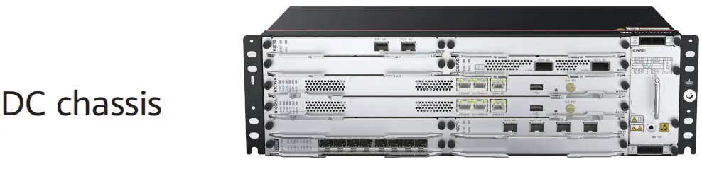
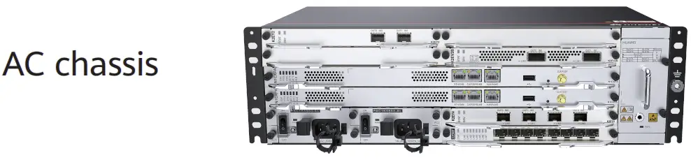
| Item | DC Chassis | AC Chassis |
| Chassis height[U] | 3 U | 3 U |
| Dimensions without packaging (H x W x D [mm(in.)] | 132.6 mm x 442 mm x 220 mm (5.22 in. x 17.4 in. x 8.66 in.) | 132.6 mm x 442 mm x 220 mm (5.22 in. x 17.4 in. x 8.66 in.) |
| Weight without packaging (base configuration) [kg(lb)] | 5.7 kg (12.57 lb) | 7.8 kg (17.2 lb) |
| Rated input voltage[V] | -48 V/-60 V | 200 V to 240 V/100 V to 127 V dual live wires, support 240V HVDC |
| Input voltage range [V] | -40 V to -72 V | 90 V to 290 V |
| Maximum input current [A] | 40 A | 10 A |
Safety Guidelines
Observe all safety regulations and precautions
- To ensure personal and equipment safety, observe all the safety precautions on the equipmentand in this document.

 an
an
 and items do not cover all the safety precautions and are only supplementary to the safety precautions.
 - Follow all the safety precautions and instructions provided by Huawei. The safety precautions outlined in this document are only requirements of Huawei and do not cover general safety regulations. Huawei is not liable for any consequence that results from violation of regulation spertaining to safe operations or safety codes pertaining to design, production, and equipment use.
Operator qualifications
Only trained and qualified personnel are allowed to install, operate or maintain the equipment. Familiarize yourself with all safety precautions before performing any operation on the equipment.
|
|

|
Before installing, operating, or maintaining the equipment, wear an ESD wrist strap and insert the other end into the ESD jack on the chassis or cabinet. Remove conductive objects like jewelry and watches to preventdamages to the equipment and cards caused by electrostatic discharge. | 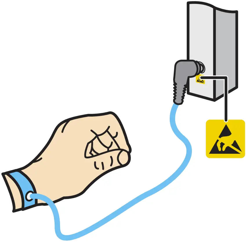 |
Site Requirements
The device to be installed must be used indoors. To ensure normal operation and long service life of the device, the following requirements must be met:
- The device needs to be installed in a clean, dry, well ventilated, and temperature-controllable standard equipment room. In addition, the equipment room must be free from leaking or dripping water, heavy dew, and condensing.
- Dustproof measures must be taken in the installation site. This is because dust will cause electrostatic discharges on the device and affect connections of metal connectors and joints, shortening the service life of the device and even resulting in device failures.
- The installation site must be free from acidic, alkaline, and other types of corrosive gases.
- The device that is operating may cause radio interference. If this is the case, relevant measures may be needed to reduce the interference.
- Generally, devices such as wireless antennas should not be installed in the equipment room. If such devices must be installed indoors, ensure that the electromagnetic environment meets relevant requirements or take necessary electromagnetic shielding measures.
The temperature and humidity in the installation site must meet device requirements described in the following table.
| Item | Requirements |
| Long-term operating temperature [°C] | DC: PTN devices: –20°C to +60°C Other devices: –40°C to +65°C AC: –20°C to +55°C |
| Storage temperature [°C] | –40°C to +70°C |
| Relative operating humidity [RH] | ATN 980C: Long-term: 5% to 95% RH, non-condensing Short-term: N/A NetEngine 8000 M8/PTN 6900-2-M8C: Long-term: 5% to 85% RH, non-condensing Short-term: 5% to 95% RH, non-condensing OptiX PTN 980/980B: Long-term: 10% to 90% RH, non-condensing Short-term: N/A |
| Relative storage humidity [RH] | ATN 980C: 5% to 100% RH, non-condensing NetEngine 8000 M8/PTN 6900-2-M8C: 5% to 95% RH, non-condensing OptiX PTN 980/980B: 10% to 100% RH, non-condensing |
| Long-term operating altitude [m] | ≤ 4000 m (For the altitude in the range of 1800 m to 4000 m, the operating temperature of the device decreases by 1°C every time the altitude increases by 220 m.) |
| Storage altitude [m] | < 5000 m |
Cabinet Requirements
The cabinet may be installed on an ESD floor or a concrete floor. Fordetails about how to install a cabinet, see the Cabinet Installation Guidedelivered with a cabinet. |
The device must be installed in an IEC 19-inch cabinet or an ETSI 21-inch cabinet.
Huawei A63B cabinet is recommended. If customers choose to purchase cabinets by themselves, the cabinets must meet the following requirements:
- 19-inch or 21-inch cabinet with a depth of greater than or equal to 300 mm.
- The cabling space in front of the cabinet complies with the cabling space requirements of boards. It is recommended that the distance between the cabinet door and any device board be greater than or equal to 120 mm. If the cabling space is insufficient, cables will block the cabinet door from closing. Therefore, a cabinet with broader cabling space is recommended, such as a cabinet with a convex door.
- The device draws air from the left side and exhausts from the right side. Therefore, if the device is installed in a 19-inch cabinet, there must be a clearance of at least 75 mm at the left and right sides of the cabinet to ensure good ventilation.
- The porosity of each cabinet door must be greater than 50%, meeting heat dissipation requirements of devices.
- The cabinet has installation accessories, such as guide rails, floating nuts, and screws.
- The cabinet has a ground terminal to connect to the device.
- The cabinet has a cable outlet on the top or at the bottom for overhead or underfloor cabling.
Installing a Device
|
Installing a Device in an IEC 19-Inch Cabinet
- Installing Components

- Install the cable management frame and power cable tray onto the device.

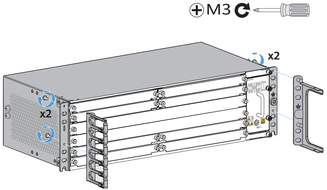
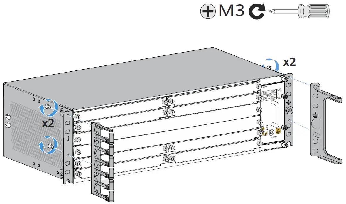
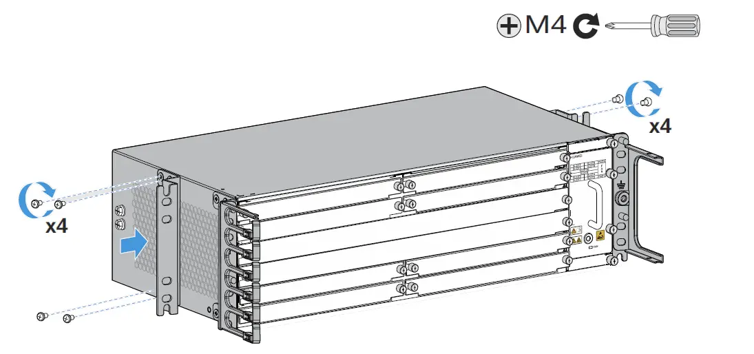
- Install conversion mounting ears on both sides of the device

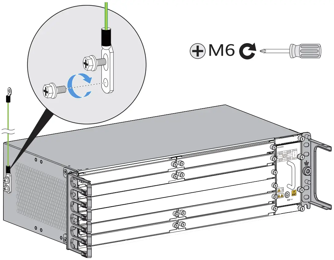
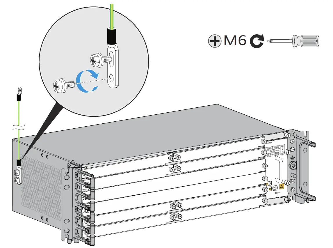
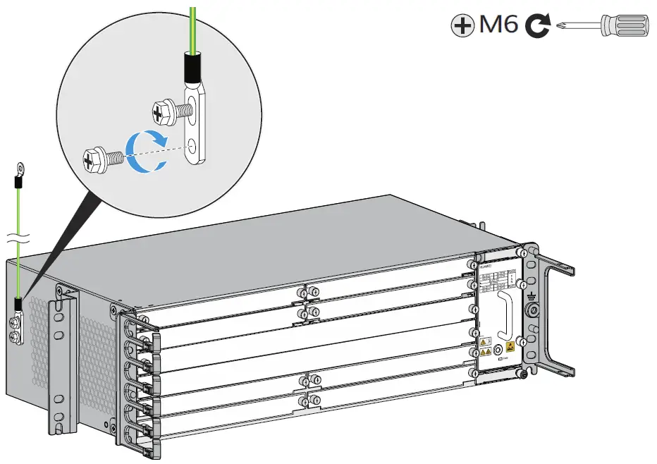
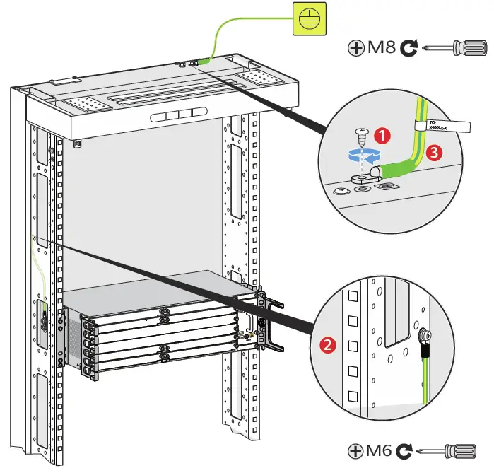
- Connect the PGND cable to the front or side face of the device. The side face is preferred.

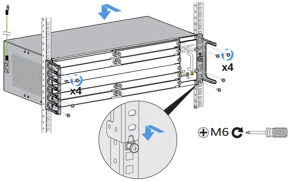
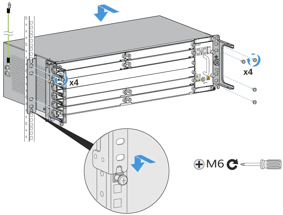
- Install the device into the cabinet.

Installing a Device in an ETSI 21-Inch Cabinet with Middle Columns
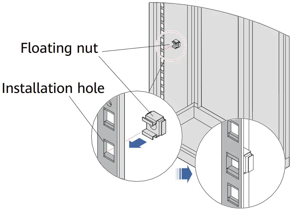
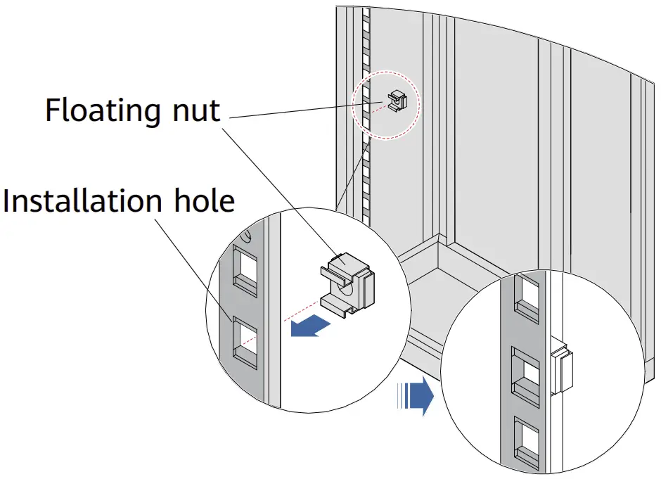
- Install floating nuts onto the cabinet.

- Install the cable management frame and power cable tray onto the device.

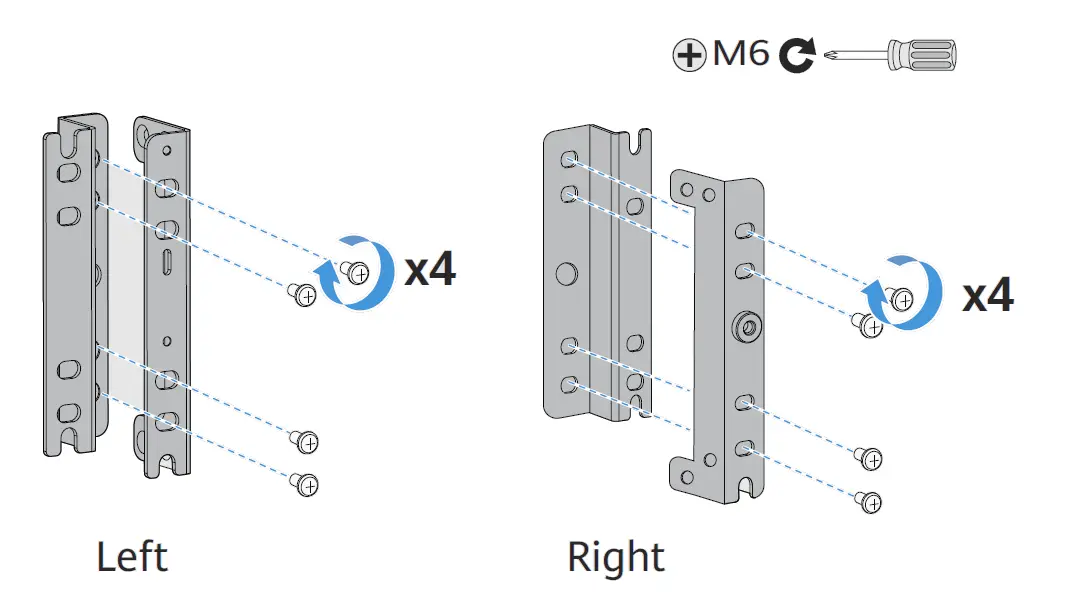
- Take out a pair of 19-inch mounting ears and install ETSI conversion mounting ears onto the 19-inch ones.

- Install the 19-inch mounting ears and conversion mounting ears on the left and right sides of the device.

- Connect the PGND cable to the front or side face of the device.
The side face is preferred.
- Install the device into the cabinet.

Installing Components
Installing Boards
Installing an interface board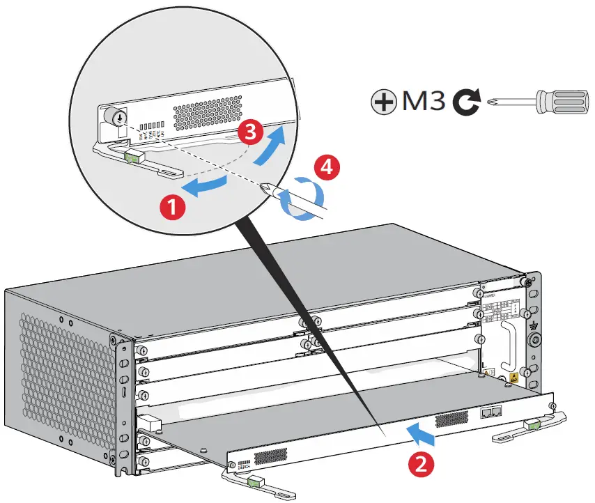
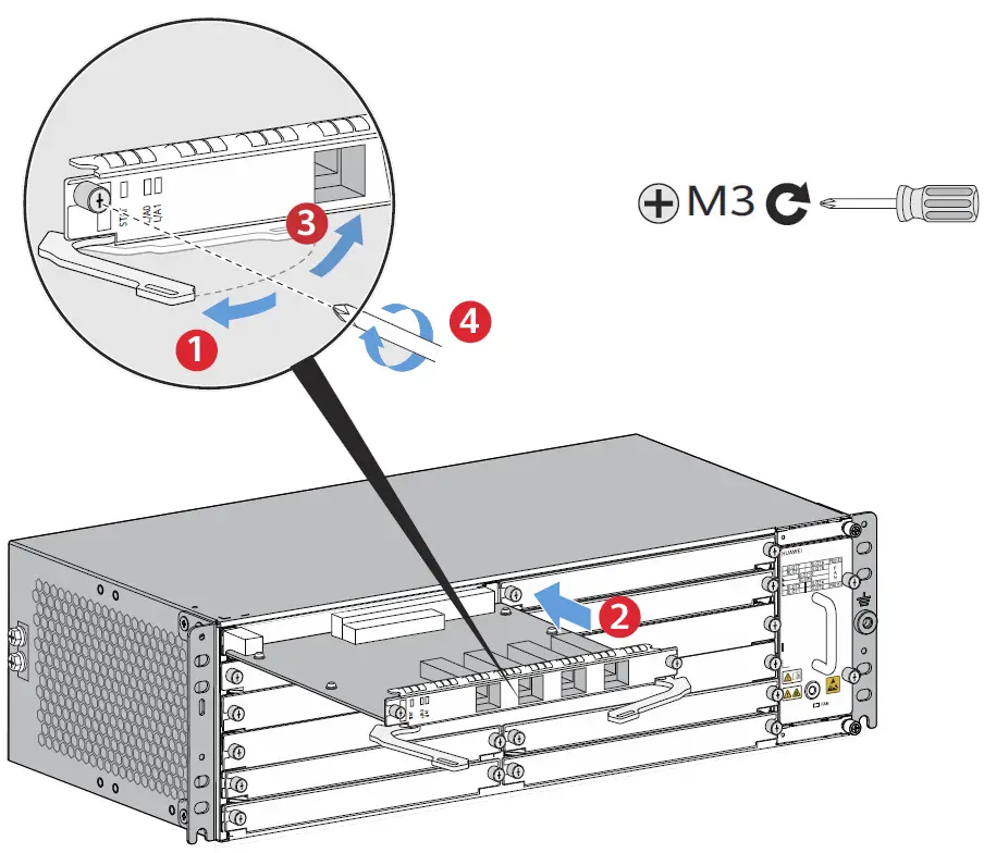
Installing a main control board
|
- Hold the ejector levers on the panel with both hands, and turn them outward until they make an angle of 45 degrees with the panel.
- Push the board along guide rails into the slot until it cannot move forward.
- Lower the ejector levers and push them inward until they cannot move forward. (When installing a main control board, ensure that the latches of the ejector levers are locked into the panel.
- Use a Phillips screwdriver to fasten the captive screws clockwise on both sides of the panel.
Installing Optical Modules STAT L/A0 L/A1

|
- Insert the optical module fully into the optical port.
- Connect optical fibers according to the required connection sequence.
- Check the LINK indicator on the corresponding optical port. If the LINK indicator is steady green, the optical module is working properly.
Connecting Cables
Common Cables
| 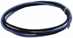 DC power cable DC power cable | 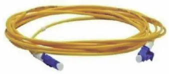 Optical fiber Optical fiber | 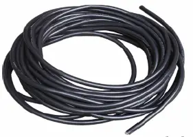 AC power cable AC power cable |
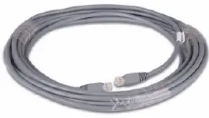 Shielded Ethernet cable Shielded Ethernet cable | 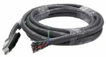 120-ohm 16 x E1 cable 120-ohm 16 x E1 cable |
|
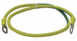 PGND cable
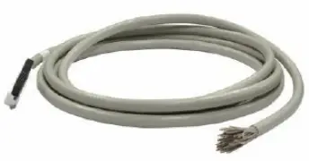
Routing Planning
|
Cable layout for a DC device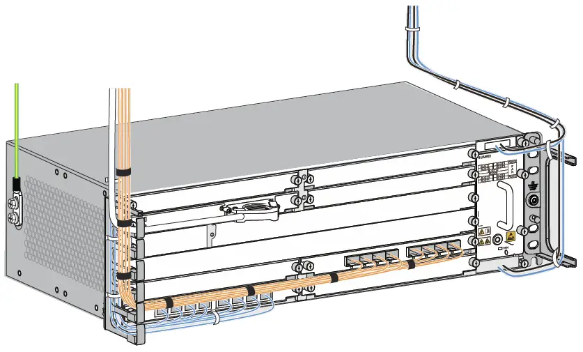
It is recommended that the power cables of a DC device be routed on the right side of the cabinet. To facilitate fan module maintenance, keep the cables away from the upper or lower fan module insertion and removal areas. |
Cable layout for an AC device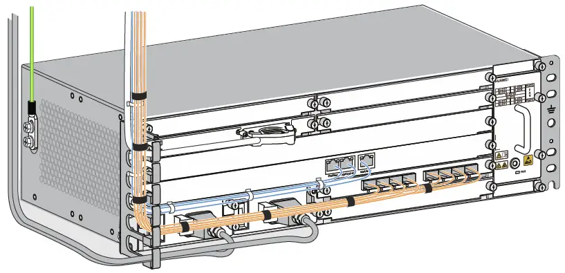
It is recommended that the power cables of an AC device be routed on the left side of the cabinet. To facilitate power module maintenance, keep the cables away from the upper or lower power module insertion and removal areas. |
Connecting Cables
Cable layout in a scenario where a 3U device shares the same cabinet with other devices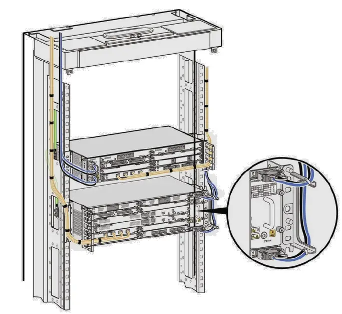
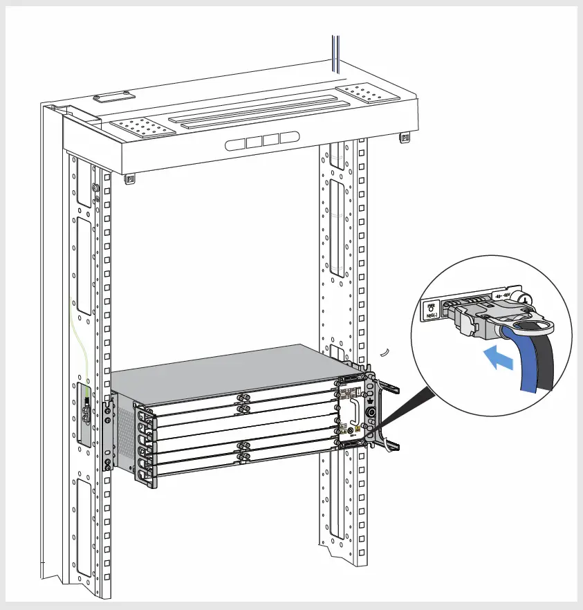
Installing a PGND Cable
Installing DC Power Cables
Check the fuse capacity of the external power supply.
| Device Model | Recommended Fuse Capacity |
| ATN 980C | 320G/360G or lower: ≥ 16 A (For long-term evolution purposes, if permitted, it is recommended that the fuse capacity be greater than or equal to 40 A.) |
| NetEngine 8000 M8 PTN 6900-2-M8C | ≥ 32 A (For long-term evolution purposes, if permitted, it is recommended that the fuse capacity be greater than or equal to 40 A.) |
| OptiX PTN980/980B | ≥ 16 A (For long-term evolution purposes, if permitted, it is recommended that the fuse capacity be greater than or equal to 40 A.) |
| Device Model | Maximum Cable Size |
| ATN 980C | 6 mm² (0 m to 13 m) or 10 mm² (14 m to 22 m) |
| NetEngine 8000 M8 PTN 6900-2-M8C | 10 mm² (0 m to 20 m) |
| OptiX PTN 980/ 980B | 6 mm² (0 m to 13 m) |
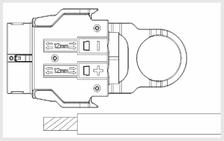
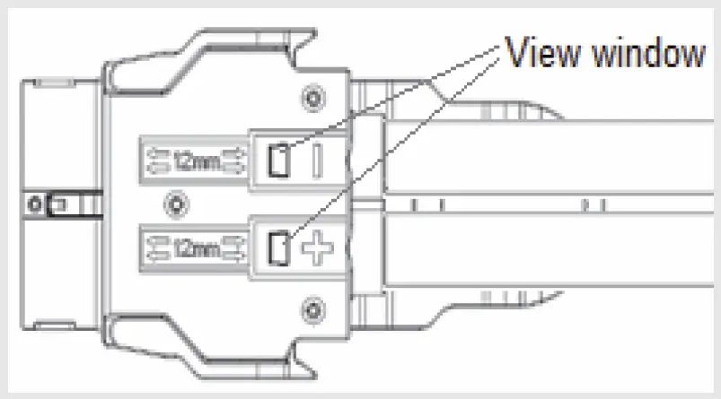
- Take out the power connector from the packaging bag, and then strip each DC power cable for a length of 6 mm to 10 mm according to the mark on the silkscreen of the connector.

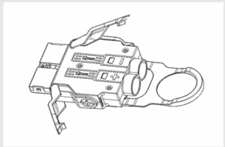
- Unfasten the connector latch.

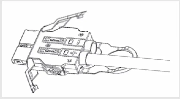
- Insert one power cable into the corresponding hole according to its pole (positive or negative).
Then, fasten the screws and latch. The method of power cable installation for the other pole is similar.
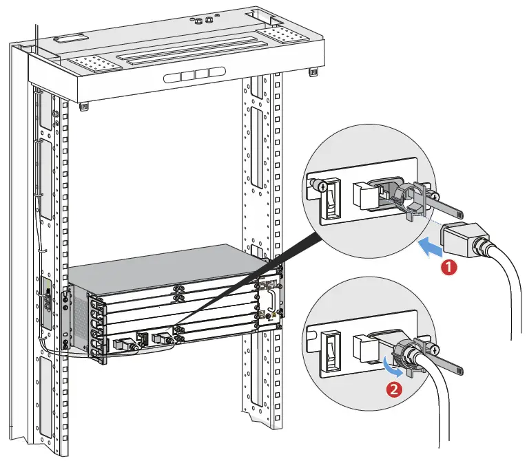
- Drag each power cable slightly to check whether it is fastened.
If the cable is loose or its core wires are exposed, disconnect the cable, cut off the split part, re-strip the cable, and then reconnect it. - Check whether the cables have been properly connected and whether the cable sheath has been pressed through view windows. If not, repeat the preceding steps to prepare and connect the cables again.

- Insert the connector into the PIU.

|
Installing an AC Power Cable
Check the fuse capacity of the external power supply.
| Device Model | Recommended Fuse Capacity |
| ATN 980C | ≥10A, ≤16A (For hierarchical power supplying protection,the current of the circuit breaker at the userside should be 10 A.) |
| NetEngine 8000 M8/PTN 6900-2-M8C |
Installing an E1 Cable
|
Installing an E1 cable with a negative 45-degree connector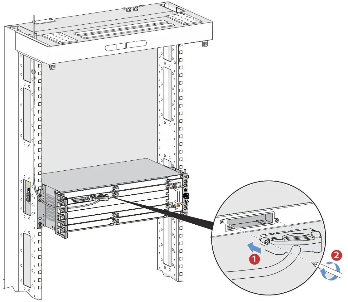
Installing an E1 cable with a positive 45-degree connector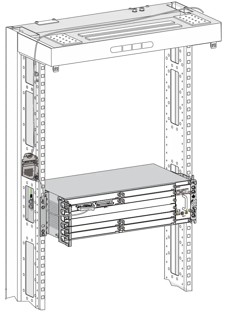
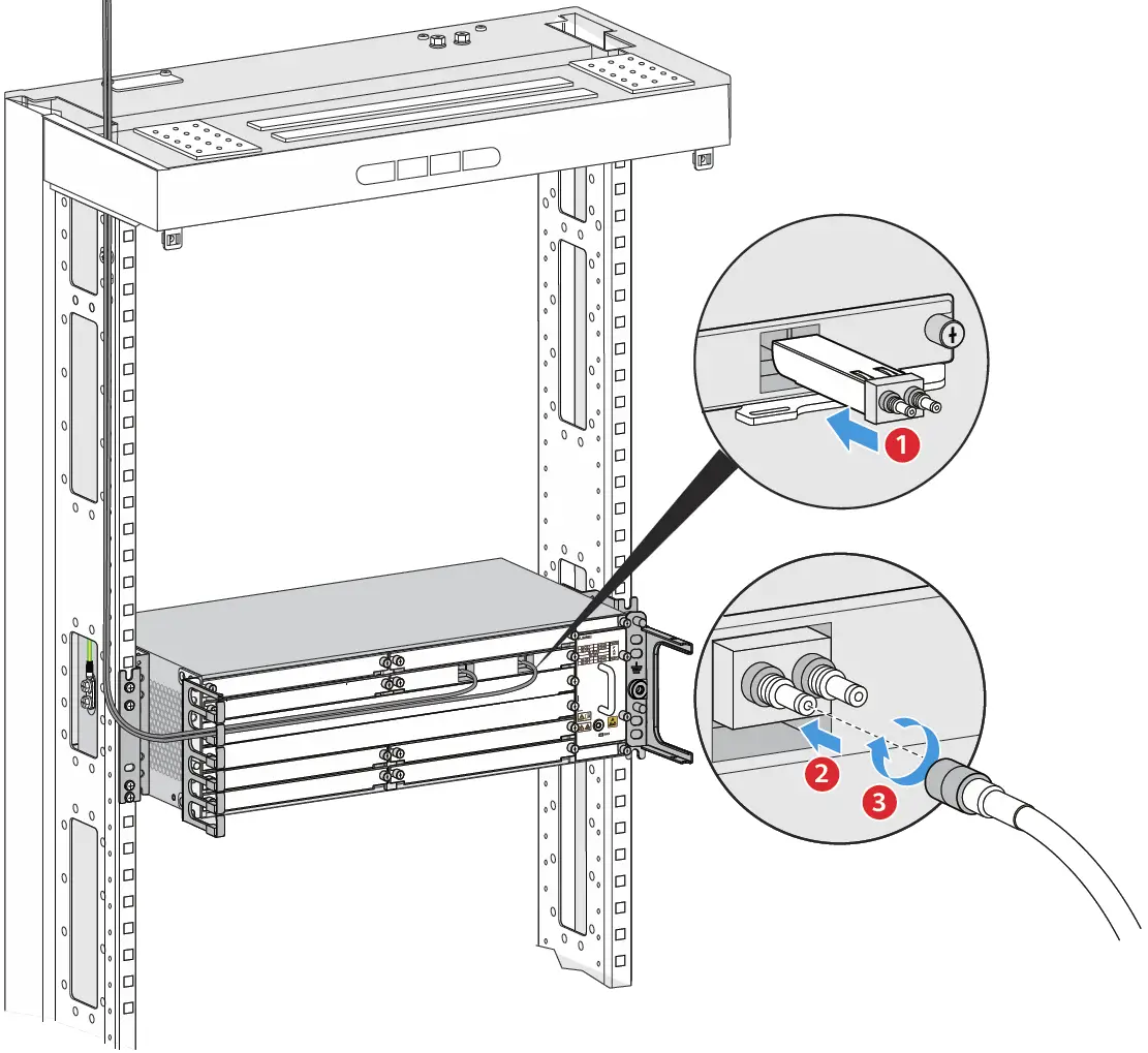
Installing Optical Fibers
When performing operations such as installing or maintaining optical fibers, do not move your eyes close to or look into the optical fiber outlet without eye protection. |
Before routing internal optical fibers, install fixed optical attenuators at the corresponding optical ports on boards according to the fixed optical attenuator installation table. If you use the recommended A63B cabinet, it is recommended that only one optical attenuator be added. If multiple optical attenuators are added, there is a risk that the cabinet door cannot be properly opened. |
|
Handling Corrugated Pipes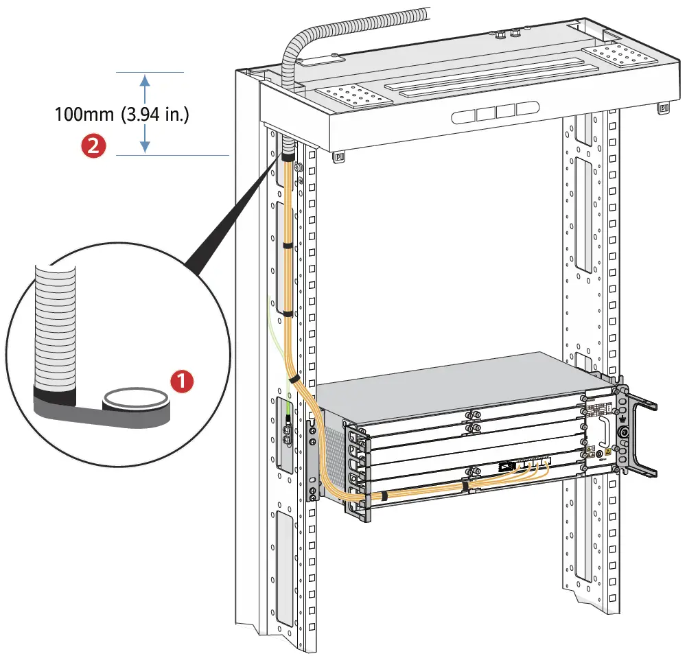
Installing Optical Fibers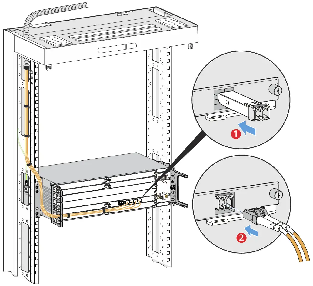
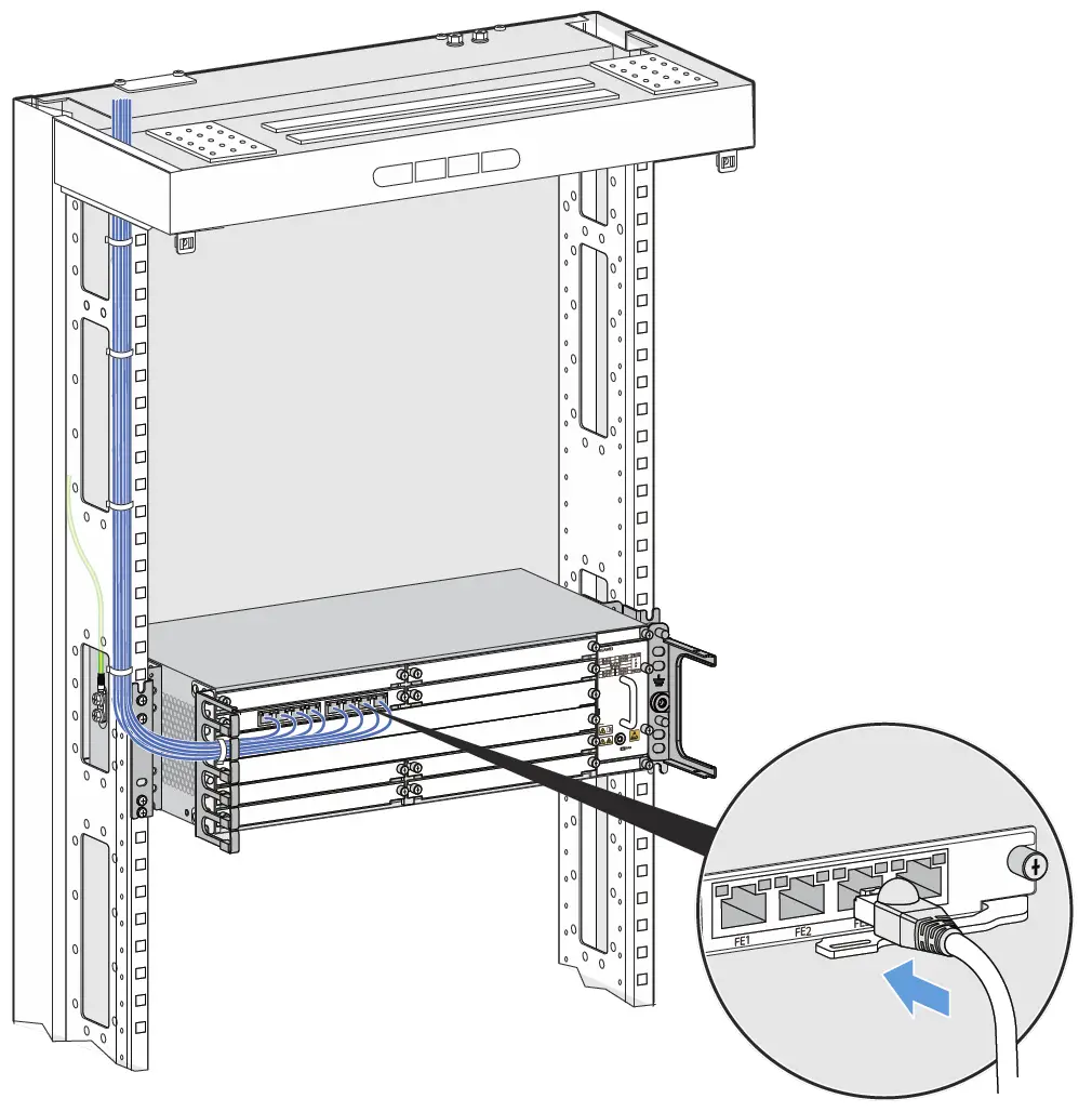
Installing Ethernet Cables
|

Installing a 75-ohm Coaxial Cable
Checking the Installation
Check Before Power-on
- Check whether fixed optical attenuators have been added in accordance with corresponding configuration rules.
- Check whether the fuse capacity of the external power supply meets requirements.
- Check whether the external power supply voltage is normal.
If the power supply voltage does not meet requirements, do not power on the device. |
Power-on Check
The following table describes the states of indicators when the device is operating properly.
If the power supply voltage does not meet requirements, do not power on the device. |
| Hardware Module | Indicator | State |
| Power module | PWR | Steady green |
| Fan module | FAN | Steady green |
| Main control board | STAT | Steady green |
| PROG | Steady green | |
| Interface board | STAT | Steady green |
| L/A | Steady green |
If board indicators are in specified abnormal states after you power on the device, handle the abnormalities onsite.
|
| Indicator | Abnormal State | Possible Cause | Handling Procedure |
| STAT | Steady red | Signals on an optical port are lost. |
|
| Steady off | The corre- sponding module cannot be detected. | If the chassis is powered on but all the indicators on the board are off, contact software commissioning engineers to replace the board. |
Obtaining Product Documentation and Technical Support
For enterprise users:
- Log in to Huawei enterprise technical support website
(https://support.huawei.com/enterprise) and select a specific product model and version to find its documentation. - Log in to Huawei enterprise support community
(https://forum.huawei.com/enterprise), and post your questions in the community.
For carrier usesrs:
Log in to Huawei carrier technical support website
(https://support.huawei.com/carrier), and select a specific product model and version to find its documentation.
Log in to carrier enterprise support community
(https://forum.huawei.com/carrier) and post your questions in the community.
Huawei Enterprise Technical Support
Huawei Carrier Technical Support\
Trademarks and Permissions
 and other Huawei trademarks are trademarks of Huawei
Technologies Co., Ltd.
All other trademarks and trade names mentioned in this document are
the property of their respective holders.
Copyright © Huawei Technologies Co., Ltd. 2021. All rights reserved.
No part of this document may be reproduced or transmitted in any form or by any means without prior written consent of Huawei Technologies Co., Ltd.
Appendix Inspecting and Cleaning Optical Fiber Connectors and Adapters
Since the 50G optical module link uses the PAM4 encoding technology, there are higher requirements on the optical fiber and cable quality and the link is more sensitive to multipath reflection interference of signals. If the fiber link connector, fiber section, or fiber splicing surface is dirty, optical signals are reflected back and forth on the fiber link, causing interference due to co-channel noise on the receive side. As a result, the optical link is unstable or intermittently disconnected. To prevent this issue, you need to check and clean the optical fiber connectors before installation. For details, see Installation and maintenance > Preparing for the installation> Inspecting and Cleaning Optical Fiber Connectors and Adapters in the product documentation.


