![]()
XCI2001-U1 Releasing Module for PRO Fire System
Installation Guide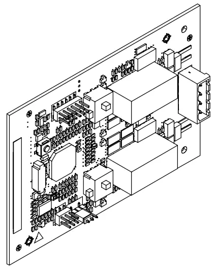
XCI2001-U1
Releasing module
Mounting Installation
XCI2001-U1 Releasing Module for PRO Fire System
Legal notice
Technical specifications and availability subject to change without notice.
Transmittal, reproduction, dissemination and/or editing of this document as well as utilization of its contents and communication thereof to others without express authorization are prohibited. Offenders will be held liable for payment of damages. All rights created by patent grant or registration of a utility model or design patent are reserved.
Issued by:
Siemens Industry, Inc.
Building Technologies Division
8 Fernwood Road
Florham Park, NJ 07932
Tel. +1 973-593-2600
www.sbt.siemens.com/FIS
Edition: 2016-10-27
Document ID: A6V10315050_e_en_–
© Siemens Industry, Inc., 2015
Description
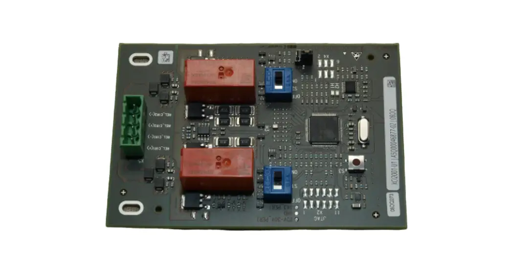
The releasing module XCI2001 supports activation of releasing valves in releasing and sprinkler systems. Activation can be event-controlled or performed manually. The releasing module is mounted on the periphery board.
Properties
- Automatic or manual activation
- Dual-channel control
- Supervision of releasing circuit (wiring as class A or class B circuit)
- Supports several valve systems
- Suited to indoor applications (not wet rooms)
Mounting
The releasing module XCI2001 is installed on the periphery board as shown and screwed onto the back box. Slot X901 is also used for the NAC module (1A/2B).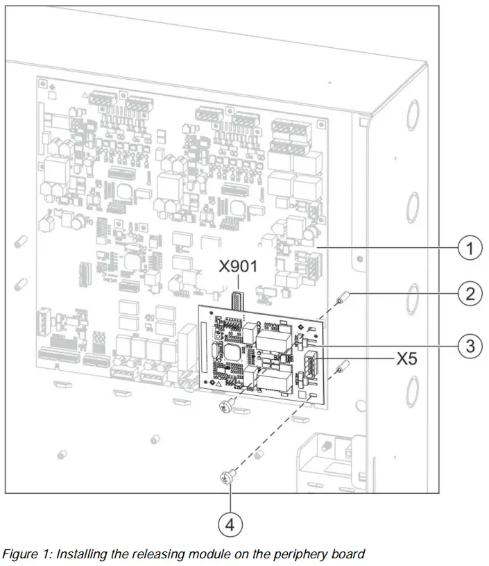
- Periphery board (250p) or periphery board (500p)
- Threaded standoffs on back box
- Releasing module XCI2001
- 2x fixing screw
X901 Slot in periphery board
X5 Connection terminal on releasing module
- Plug the releasing module (3) into slot X901 on the periphery board.
- Fasten the releasing module to the threaded standoffs (2) in the back box using the two fixing screws (4).
- Wire up the releasing module according to the pin assignment.
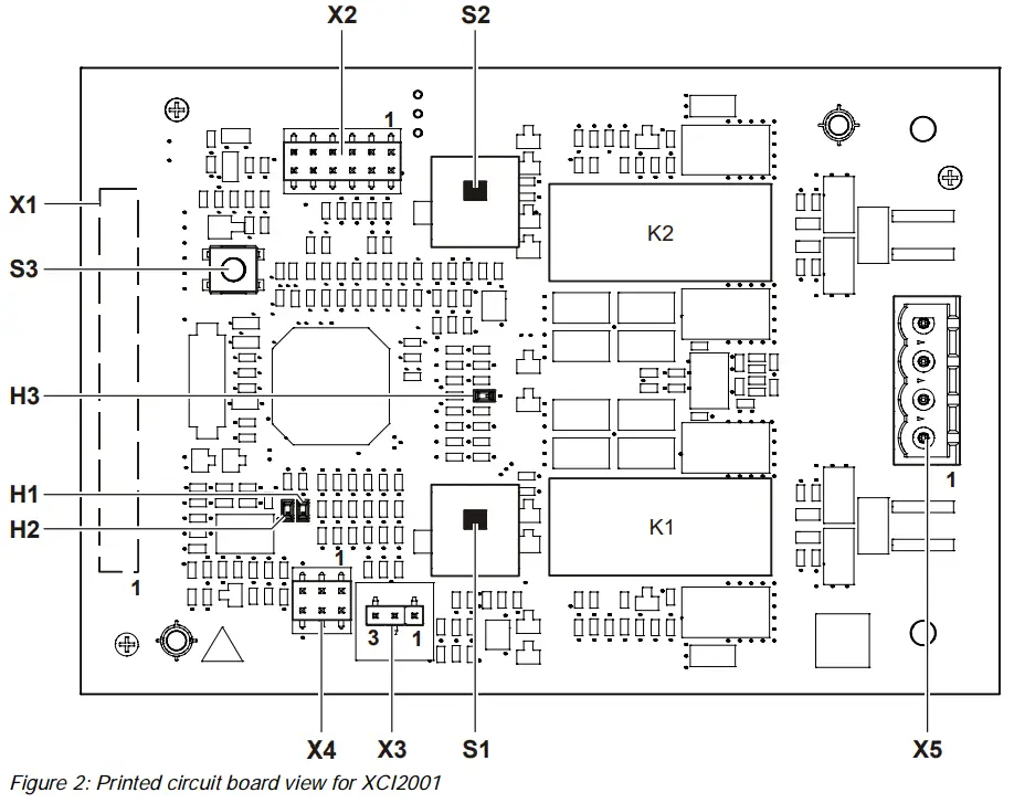
Views
| Element | Des. | Function |
| Connector
| X1 | Plug for periphery board connection |
| X2 | Service plug for programmed connection (not used) | |
| X4 | Diagnostic service plug (not used) | |
| X5 | Releasing relay outputs | |
| Adjustment elements
| S1* | Switch: Arm/Disarm releasing output 1 |
| S2* | Switch: Arm/Disarm releasing output 2 | |
| S3 | Reset key | |
| X3 | Jumper for degraded mode enable | |
| LEDs
| H1 | Display: Releasing output 1 status ON/OFF |
| H2 | Display: Releasing output 2 status ON/OFF | |
| H3 | Flashing: Releasing module is active |
* For Class A wiring, both S1 and S2 must be in the same position at all times when used to disarm or arm the circuit.
Pin assignments for releasing module
4.1 X5 plug connection for releasing relay output
| Pin | Designation | Description |
| 4 | REL_CIR1 (+) | Relay output for releasing 1 |
| 3 | REL_CIR1 (-) | Relay output for releasing 1 |
| 2 | REL_CIR2 (+) | Relay output for releasing 2 |
| 1 | REL_CIR2 (-) | Relay output for releasing 2 |
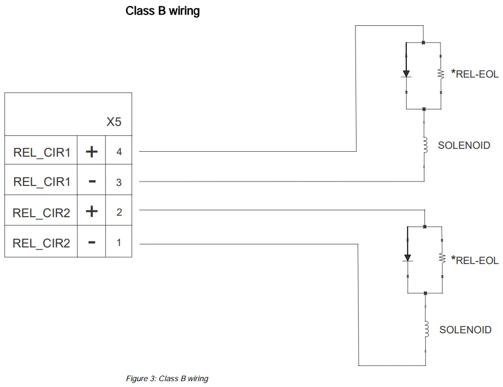
Admissible cable cross-section: 12…18 AWG, unshielded XCI2001-U1 supports two Class B circuits or one Class A circuit as shown below:
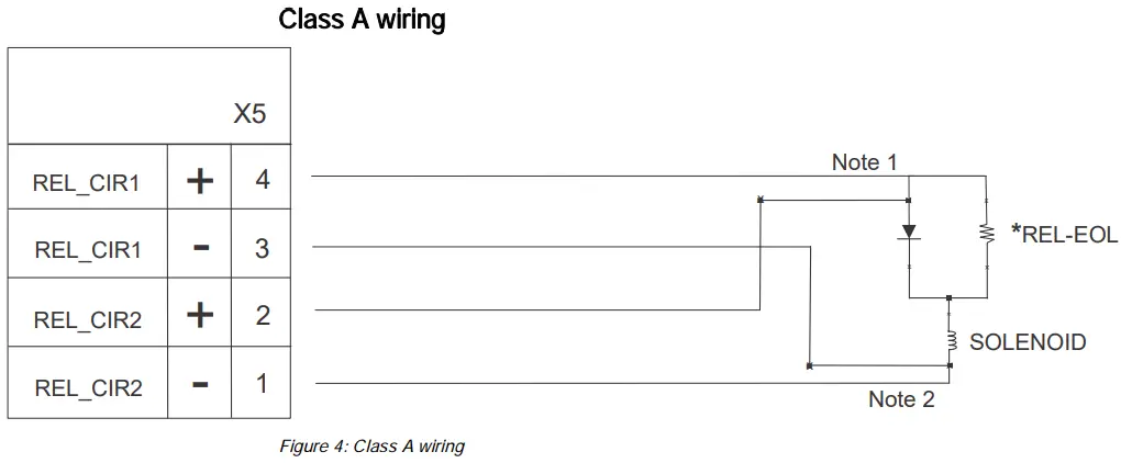
Note 1 Loop wires must be terminated directly onto the SOLENOID
Note 2 Loop wires must be terminated directly onto the SOLENOID
*REL-EOL: Terminating resistor 24 kΩ and diode (Siemens part number 500-696359)
The maximum length of line of the relay connections is limited to a resistance of 3.5 Ω.
Indicators
LED indicators
| LED | Color | Function | Condition | Meaning |
| H1 | Green | Status of releasing circuit 1 | Off | Releasing circuit 1 inactive |
| On | Releasing circuit 1 activated | |||
| H2* | Green | Status of releasing circuit 2 | Off | Releasing circuit 2 inactive |
| On | Releasing circuit 2 activated | |||
| H3 | Green | Status of processor | Off (steady) | Processor is not running |
| Flashing | Processor is running | |||
| On (steady) | Processor is not running |
* Not applicable for Class A wiring.
Adjusting elements for releasing module
S1 and S2, switches to arm/disarm the releasing outputs
| Button | Function | Position | Meaning |
| S1 | Arming of releasing 1 | OFF | Releasing output 1 disarmed (supervisory mode) |
| ON | Releasing output 1 armed (normal) | ||
| S2 | Arming of releasing 2 | OFF | Releasing output 2 disarmed (supervisory mode) |
| ON | Releasing output 2 armed (normal) |
S1 and S2 control output
- The outputs are disarmed in the OFF position. The relays are disarmed but are still supervised.
- The outputs are armed in the ON position.
- For Class A wiring, both S1 and S2 must be in the same position at all times when used to disarm or arm the circuit.
S3, reset key for releasing module
| Button | Function | Position | Meaning |
| S3 | RESET | Pressed | The module is reset. |
Jumper X3, degraded mode enable for releasing
| X3 | Jumper position | Function | Meaning |
| 3 – 2 | Activated | No degrade operation allowed (Default) | |
| 1 – 2 | Deactivated | Degrade operation allowed |
Jumper X3 must agree with the panel configuration or a trouble will be displayed.
Technical data
| Supply input | Voltage | DC 24 V |
| Quiescent current | 11 mA at DC 24 V | |
| Output voltage | DC 24 V Special Application | |
| Output current | 2.0 A per output channel | |
| Connection terminals | Design | Screw terminals |
| Admissible cable cross-section | 12AWG…18AWG, not shielded | |
| Relay outputs | Maximum line resistance | 3.5 Ω |
| Preauction deluge | Maximum line resistance | 2.5 Ω |
| Minimum voltage at the coil | DC 20.4 V | |
| Mechanical data | Dimensions (W x H) | ~3.25 x 4.75″ / ~8.25 x 12.05 cm |
| Weight | Approx. 3.2 oz. / 90 g |
FCC Statement
| Installation and usage of equipment is not in accordance with instructions manual Radiation of radio frequency energy Interference to radio communications ● Install and use equipment in accordance with instructions manual. ● Read the following information. |
This equipment generates, uses, and can radiate radio frequency energy and if not installed and used in accordance with the instructions manual, may cause interference to radio communications.
It has been tested and found to comply with the limits for a Class A computing device pursuant to Part 15 of FCC Rules, which are designed to provide reasonable protection against such interference when operated in a commercial environment.
Operation of this equipment in a residential area is likely to cause interference in which case the user at his own expense will be required to take whatever measures may be required to correct the interference.
Issued by
Siemens Industry, Inc.
Building Technologies Division
8 Fernwood Road
Florham Park, NJ 07932
+1 973-593-2600
www.sbt.siemens.com/FIS
© Siemens Industry, Inc., 2015
Technical specifications and availability
subject to change without notice.
Document ID: A6V10315050_e_en_–
SAP order no.: A5Q00050764
FS20/FS920
Edition: 2016-10-27
firealarmresources.com


