SIEMENS FC901 Addressable Fire Alarm Control Panel System

Accessories and separate parts
| Accessories | Content | Installation instruction | Quantity |
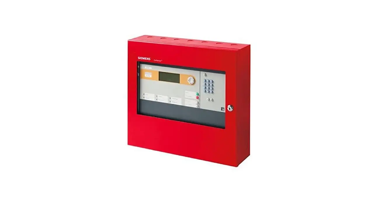
| 1 | 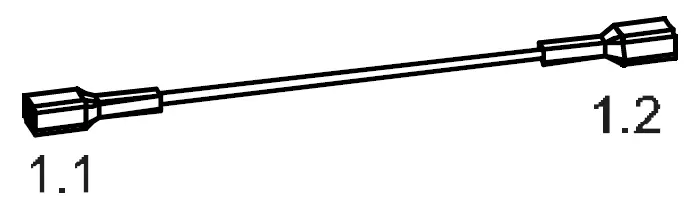 | Cable between batteries, refer to figure 1 | 1 |
| 2 | 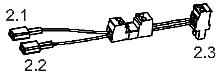 | Cable between batteries and main board, refer to figure 1 and figure 2 | 1 |
| 3 | 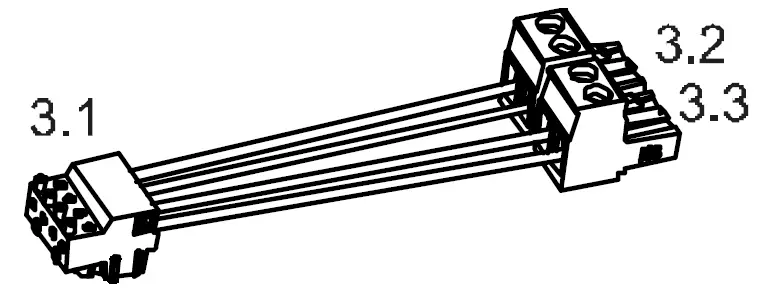 | Cable between City tie board and main board, refer to figure 2 | 1 |
| 4 | 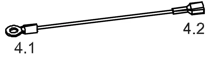 | Earth cable between enclosure and main board, refer to figure 1 and figure 2 | 1 |
| 5 | 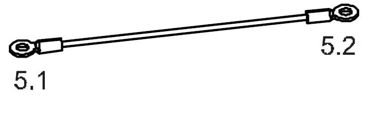 | Grounding cable for front door and power supply, refer to figure 1 | 2 |
| 6 |  | Battery bracket left, refer to figure 1 | 1 |
| 7 |  | Battery bracket right, refer to figure 1 | 1 |
| 8 |  | Cable ties | 10 |
| 9 |  | No.8 screws, refer to figure 1 | 12 |
| 10 |  | No.4 screws, refer to figure 2 | 2 |
| 11 |  | Spacer for City tie board, refer to figure 2 | 2 |
| 12 |  | Power supply MOV (Metal Oxide Varistor), refer to figure 2 | 1 |
| S1 |  | Battery cell, refer to figure 1 | 2 |
| S2 |  | Power supply, refer to power supply installation instruction sheet delivered with power supply | 1 |
| S3 |  | Front door hinge axis lock pin, refer to Detail A | 2 |
| S4 |  | Front door hinge axis, refer to Detail A | 2 |
| S5 |  | EOL for NAC, refer to Detail C | 2 |
Note: Item 3,6,7,11,S1and S2 are not delivered with the FC901 and FC2005, and should be ordered separately.
Assembling notes
- Mount the batteries with battery brackets.
- Mount the power supply MOV, then mount the power supply to the enclosure.
- Mount the City tie module onto the main board according to the Figure 2 (City tie module is optional).
- Connect the cables to the corresponding position marked on the drawing. (The power supply input cable and output cable are not included in the FC901 and FC2005 package.)
- Mount the Main board assembly onto the Enclosure according to Figure 3.
- Mount the Lock pin to the Front door axis. (Both are included in the Enclosure package.)
NOTICE
Pay attention to the battery polarity at 2.1 and 2.2
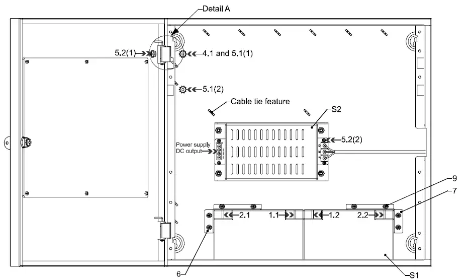 Figure 1: Installation instruction (Front view with front door open)
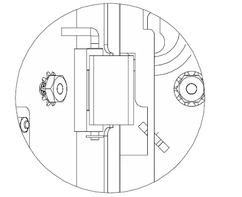 Detail A: Front door hinge and lock pin installation instruction
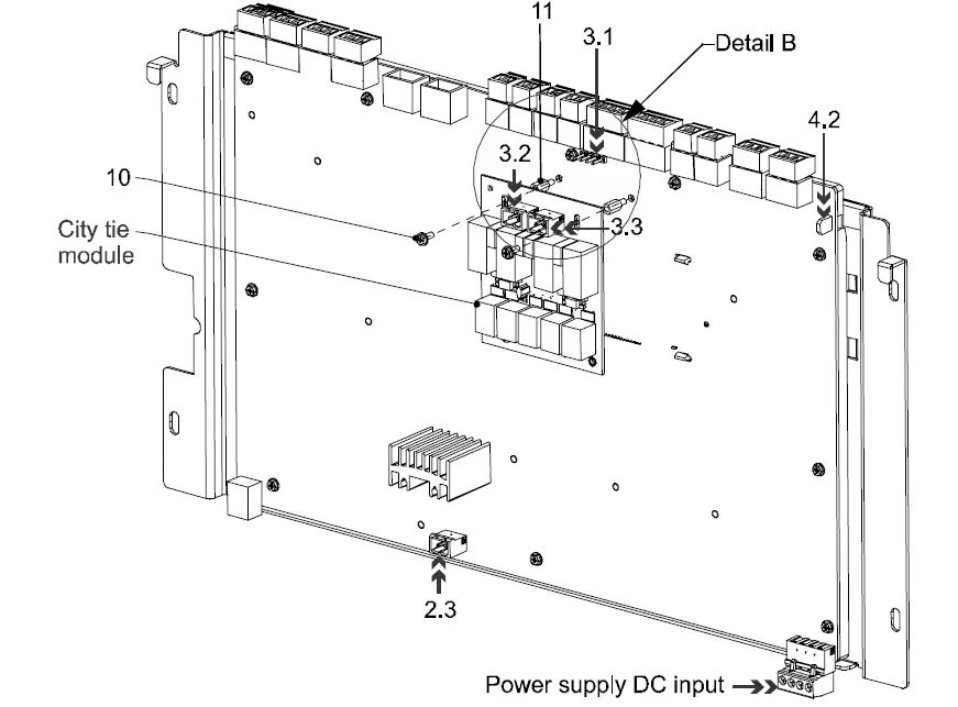
Figure 2: Installation instruction (Main board assembly back view) 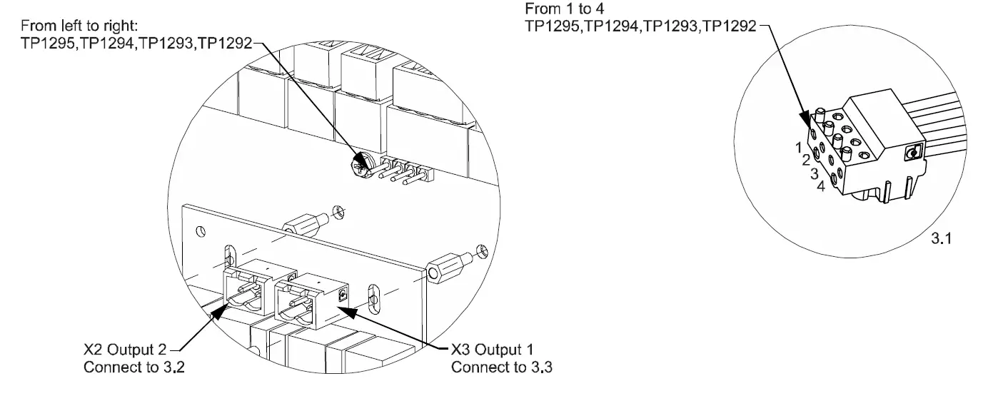
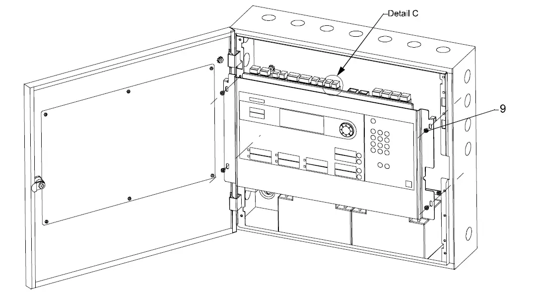 Figure 3: Main board assembly installation instruction
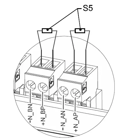 Detail C: NAC EOL installation instruction
Steps:
- Bend the MOV connector pin according to the figure below.

- Fix or weld the MOV onto the power input connector.

- Fix the AC input cable and screws on the connector.


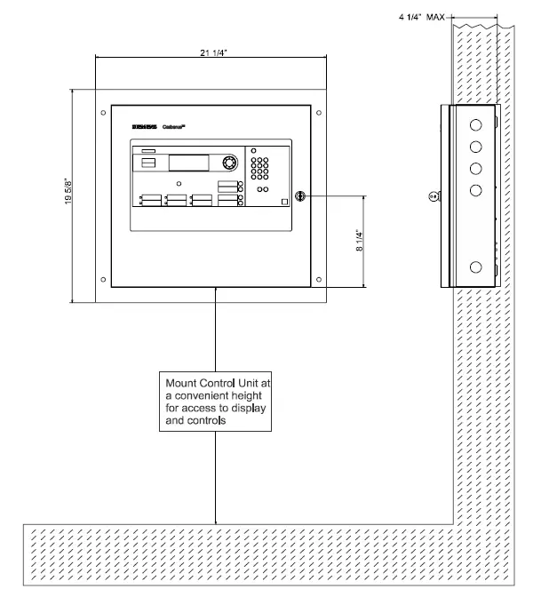
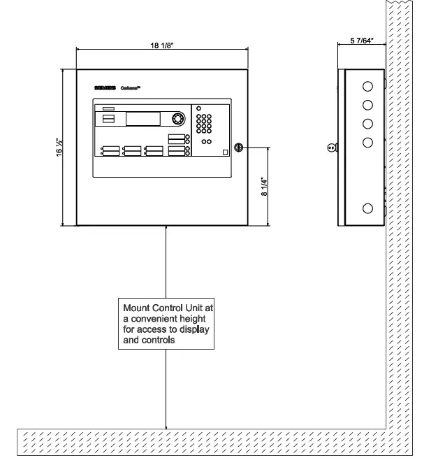
Installation instruction with trim kit
Technical data
Environmental
Operating temperature -32-120°F (0-49°C)
Relative humidity – Up to 93% @ 90°F (32°C)
To be installed in an indoor dry protected environment only
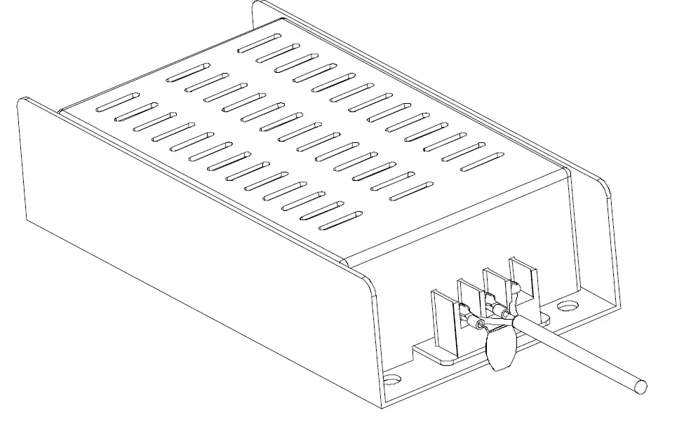
Primary Power Supply (FP2011-U1)
Input: 120 VAC, 60 Hz or 240 VAC, 50 Hz
@ 2.0 A max.
Supervised
Output: 26 VDC @ 6.5 A max.
Max current: 6.5 A (2 hours max.)
Filtered and Regulated
Secondary Power Supply
24 V lead-acid battery set
Max. charged voltage: 27.8 VDC
Automatic low battery disconnect voltage: 19.2±0.1 VDC Max. charge current: 0.45 A
Battery capacity:12 AH internally to 18 AH with separate enclosure FH2072-UA
Supervised
Auxiliary Power Outputs
| Non-resettable power output | Resettable power output |
| Power limited | Power limited |
| Current: 0.75 A | Current: 0.75 A |
| Voltage: 19 to 28 VDC | Voltage: 19 to 28 VDC |
| Ripple: 0.1 VAC | Ripple: 0.1 VAC |
| Special Application | Special Application |
Status Relays
Non-power limited
One programmable relay
Three non-programmable relays: Trouble, Supervisory, Alarm
Contact rating: 2 A, 30 VDC maximum
Form C contact
Notification Appliance Circuits
Power limited Supervised
| Current Draw | Maximum Line Resistance |
| 2.5 A | 3.2 Ω |
| 2.0 A | 4.0 Ω |
| 1.5 A | 5.3 Ω |
| 1.0 A | 8.0 Ω |
| 0.5 A | 16.0 Ω |
Alarm voltage: 16 to 32 VDC
Maximum ripple: 0.1 VAC
Used for special application only
Two Class B or one Class A
Total Max. Current: 2.5 A
Serial Interface Circuit (UFP)
Power limited
Supervised
Maximum wire loop resistance: 50 Ω total Physical layer: RS485
SLC Addressable Device Circuits
Max. 32 VDC
Power limited
Supervised
Max. current: 0.07 A (RMS)
Maximum wire loop resistance: 50 Ω
Two Class B or one Class A circuit
Max. 50 addressable devices
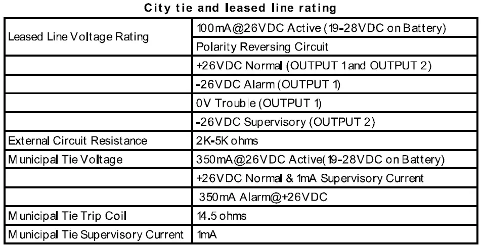
City Tie Circuits
Supply Input:
Voltage: 26 VDC / 18 – 28 VDC for battery
Current: Max. 0.4 A
Supervised
Output
City Tie-Output 1
Normal output voltage: 19-28 VDC (open circuit condition) Supervisory current: 1 mA
Maximum trip current: 400 mA
Maximum coil plus wire resistance: 22.5 Ω
Leased line-Output 1
Normal output voltage: 19-28 VDC (open circuit condition) Trouble output voltage: 0 V
Alarm output voltage: -(19-28) VDC (open circuit condition) Maximum wire resistance: 2-5 KΩ
Maximum short circuit current: 25 mA
Leased line-Output 2
Normal output voltage: 19-28 VDC (open circuit condition) Supervisory output voltage: -(19-28) VDC (open circuit condition)
Maximum wire resistance: 2-5 KΩ
Maximum short circuit current: 25 mA
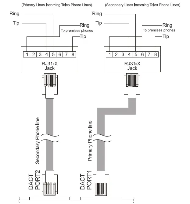
DACT Circuits
Power limited
Supervised for short or open circuit conditions Compliance to FCC part 68
Support RJ31X connection
Compatible Digital Alarm Communication Receiver (DACR) list,
| Device Module | Manufacture |
| MX8000 | Honeywell |
CAUTION:
- To reduce the risk of fire, use only No. 26 AWG or larger telecommunication line cord.
- Only to a loop start telephone circuit and not to a ground start telephone circuit.
- To verify the integrity of the call forwarding feature every 24 hours.
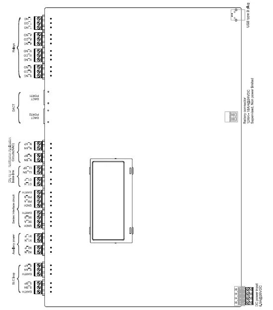
FC901/FC2005 system connection diagram
 NOTICE
All the wiring must be in accordance with local codes and the National Electric Code.
SLC loop connections
Supervised and power limited. Refer to the user manual (A6V10333722 and A6V10336754) Appendix B to get detailed device compatibility list for FC901 and FC2005. 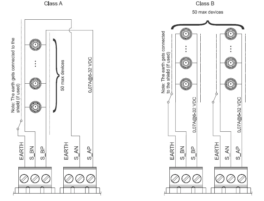
Auxiliary power
Non-supervised and power limited
Auxiliary power output 2 (Resettable, power limited) 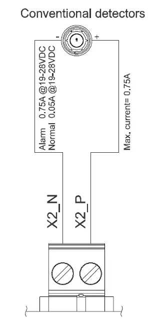
Auxiliary power output 1 (Non-resettable, power limited) 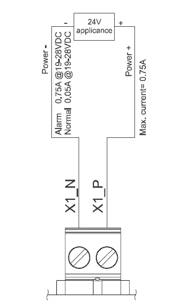
Series interface circuit
Power limited 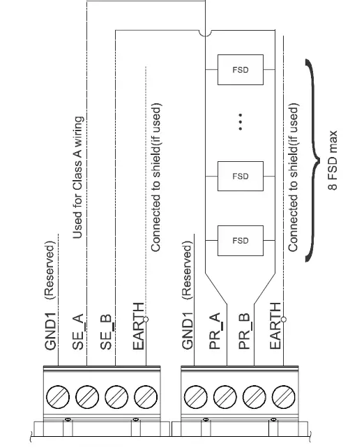
City tie or lease line
Power limited 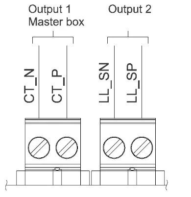
Notification application circuits
Supervised, power limited, max. current (NAC A + NAC B) = 2.5 A 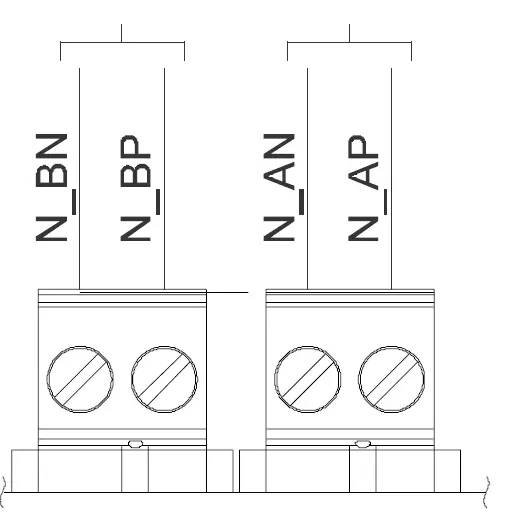
DACT
Power limited
DACT compatibility list
| Device module | Manufacture |
| MX8000 | Honeywell |
Relays
Non power limited, 2.0 A @ 30 VDC (resistive), 0.5 A @ 30 VAC (resistive) 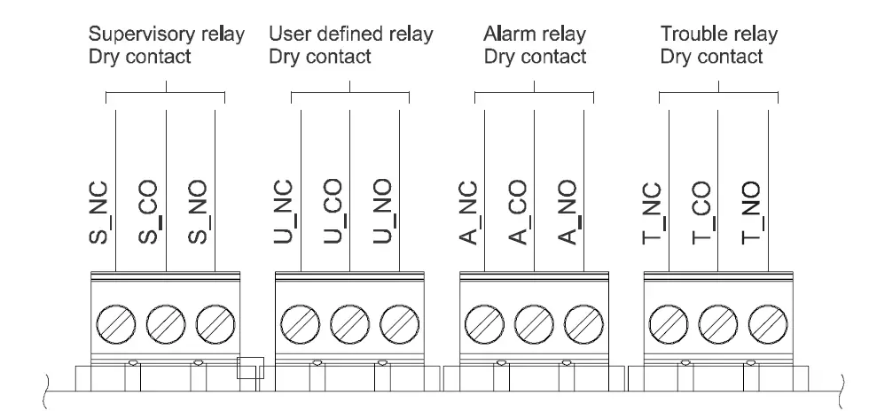
Issued by
Siemens Industry, Inc. Smart Infrastructure
8 Fernwood Road Florham Park, NJ 08932 Tel. +1 973-593-2600 www.sbt.siemens.com/FIS
© Siemens Industry, Inc., 2019
Technical specifications and availability subject to change without notice.


