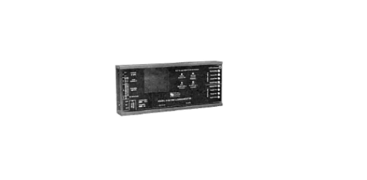
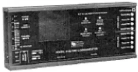
SIEMENS 5128 Digital Fire Communicator
OPERATION
The SIEMENS MXL reports system conditions to a Central Station using the Silent Knight Model 5128/ 5129, a four-channel digital communicator that reports alarm, trouble, supervisory, and miscellaneous status. When used with the MXL, the Silent Knight Model 5128/5129 uses the alarm, trouble, and supervisory channels. The miscellaneous status channel may be used to annunciate conditions other than fire at the Central Station.
ELECTRICAL CHARACTERISTICS
- Supervisory: 60mA, 18-40 VDC
- Alarm: 130mA, 18-40 VDC
INSTALLATION
Remove all system power before installation, first battery and then AC. (To power up, connect the AC first and then the battery.)
Mounting
Silent Knight Model 5128
Mount the Silent Knight Model 5128 within the MXL enclosure. Alternate mounting for the Silent Knight 5128 may include double-sided tape, velcro, or snaptrack.
Silent Knight Model 5129
The Silent Knight Model 5129 must be mounted adjacent to the MXL Control Panel and within 20 feet of it using an electrical conduit.
Electrical
The MXL Control Panel connects to the Silent Knight Model 5128/5129 Digital Fire Communicator using the Alarm, Trouble, and Supervisory dry contacts on the MXL Main Board (See Figure 1) Refer to the Silent Knight 5128/5129 Fire Slave Communicator Installation Manual, P/N 150805, provided with the Silent Knight Model 5128/5129 for dialer instructions.
The Silent Knight Model 5128/5129 monitors all System troubles through the MXL trouble relay. The MXL delays the AC fail trouble signal in accordance with NFPA and UL requirements. In NFPA 72 Remote Station install batteries to provide 60 hour standby capacity. For signalling service DACT wire according to the Figure 1. In NFPA 72 Central Station connections AC fail reporting is delayed. The delay is typically 6 hours (25% of 24 hours). Only the reporting of the trouble is delayed. AC power must be present for a full minute before the system switches back to AC power from the battery.
Using the optional AC monitor input (See Figure 1), the Silent Knight Model5128/5129 monitors AC fail trouble. When the MXL System reports an AC fail trouble, the Slent Knight Model 5128/5129 sends a specific code to the Central Station that identifies the trouble as AC fail. Refer to the MXL/MXLV Manual, P/N 315-092036 for MXL System information.
PROGRAMMING
The Silent Knight Model 5230 LCD Keypad Program mer can be connected temporarily to Pin P4 on the Silent Knight 5128 Main Board (See Figures 1 and 2) for on-site programming or troubleshooting of the communicator. English language messages assist in entering data, changing the 24-hour test time, and describing conditions currently in effect.
Table 1 lists the recommended program for the Silent Knight 5128/5129 Digital Fire Communicator. Before you begin programming, read the Step Program- ming Form in the Silent Knight Model 5128/5129 Fire Slave Communicator Installation Manual, PlN 150805, provided with the Silent Knight 5128/5129.
Silent Knight Model 5128/5129 Programming Table
| Step No. | Option Name | Select | Step No. | Option Name | Select |
| 1 | ZONE ACTIVE | 0 | 21 | RINGS | SKIP See Note 2 |
| 2 | ZONE SUPERVISED | yes | 22 | 3/1 ALARM CODE | |
| 3 | ALARM CHANNEL INPUT | 0 | 23 | 3/1 TROUBLE CODE | |
| 4 | TROUBLE CHANNEL INPUT | 0 | 24 | 3/1 RESTORE CODE | |
| 5 | SUPERVISORY CHANNEL | 0 | 25 | 3/1 TEST CODE | |
| 6 | ZONE RESPONSE 1 | 0 | 26 | 3/1 SPRINKLER SUPERVISORY | |
| 7 | ZONE RESPONSE 2 | SKIP See Note 2 | 27 | ALARM 1 FIRST | yes |
| 8 | ZONE RESPONSE 3 | 0 | 28 | TROUBLE 1 FIRST | yes |
| 9 | ZONE RESPONSE 4 | 0 | 29 | TEST 1 FIRST | yes |
| 10 | RELAY 1 | 1 | 30 | ACCOUNT 1 | |
| 11 | INSTALLERS CODE | 31 | ATTEMPTS 1 | 3 | |
| 12 | OPERATORS CODE | 32 | FORMAT 1 | ||
| 13 | DIALER TYPE | 0 | 33 | PHONE 1 | |
| 14 | COMPUTER ENABLE | no | 34 | ACCOUNT 2 | |
| 15 | TOUCHTONE LINE 1 | yes | 35 | ATTEMPTS 2 | 3 |
| 16 | TOUCHTONE LINE 2 | yes | 36 | FORMAT 2 | |
| 17 | MUST REPORT 1 | yes | 37 | PHONE 2 | |
| 18 | MUST REPORT 2 | yes | 38 | COMPUTER ACCOUNT | SKIP See Note 2 |
| 19 | AC MONITORING | 2 | 39 | COMPUTER PHONE | SKIP See Note 2 |
| 20 | AC LOSS HOURS | See Note 4 | 40 | TEST TIME | |
| 41 | CURRENT TIME |
NOTES
- If the selection is left blank, the user must fill in the proper information.
- Skip= No selection is required.
- After each selection is made, press the ENTER key to proceed to the next step.
- For Systems Configured as NFPA 72 Local, enter 6 hours.
- For Systems Configured as NFPA 72 Auxiliary or Remote Station, enter 15 hours.
NOTES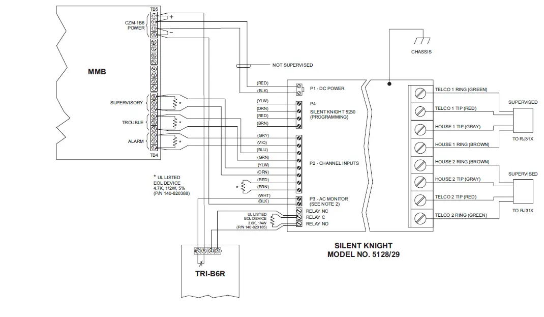
- TRI-60RI-B6RI-R input must be programmed in CSG-M as trouble causing.
- TRI-6ORI-B6RI-R output must be programmed in CSG-M to transfer on loss of AC Mains.
- All wiring supervised except as noted.
- For Remote Station, provide 60-hour battery capacity.
ADDRESS
Siemens Building Technologies, Inc.
- 8 Fernwood Road
- Florham Park, New Jersey 079332 P/N 315-093294-4
Siemens Building lechnologies, Ltd
- 2 Kenview Boulevard
- Brampton, Ontario L6T 5E4 CN
Technical Manuals Online: http://www.tech-man.com


