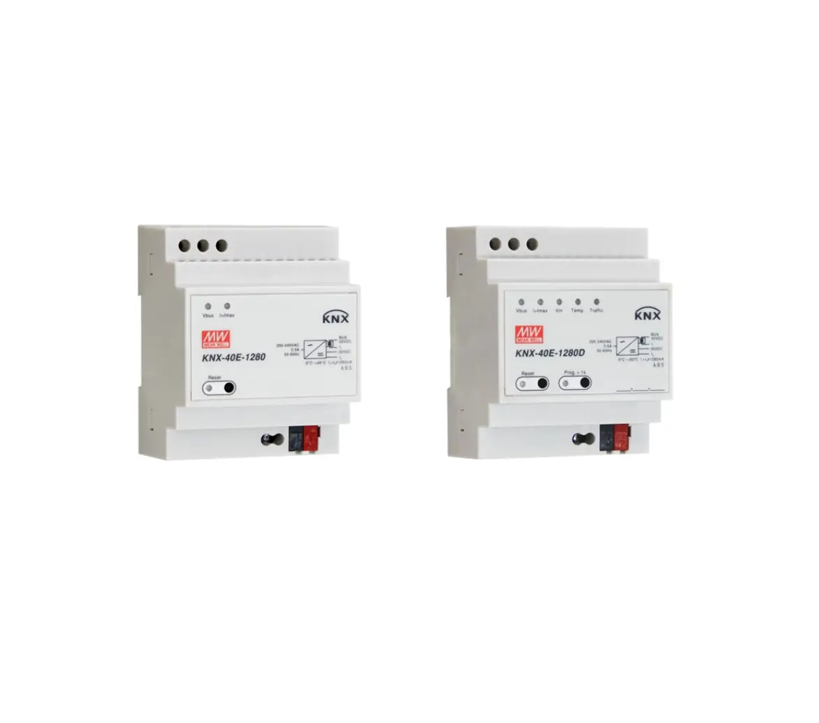
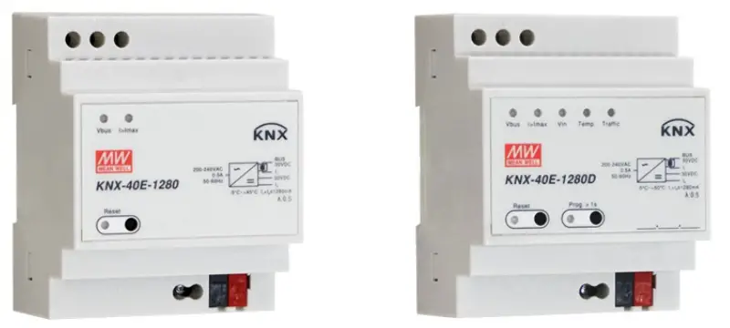
MEAN WELL KNX-40E Switching Power supply
Features
- EIB / KNX power supply with integrated choke
- Compact size with 4SU width(72mm)
- Safety extra low voltage(SEL V)
- Suitable for TP1 -256
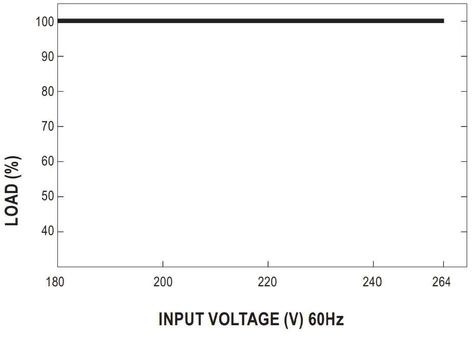
- 180~264VAC input
- Protections: Short circuit / Overload(short-circuit-proof)/ Over voltage
- Cooling by free air convection
- Isolation class I
- LED indicator for normal operation, bus reset and bus overload
- Monitoring of output voltage, output current, bus traffic load and device temperature
- Provide Wide variety of diagnostic and logic function
- Over Voltage category III
- 3 years warranty
Description
MEAN WELL. the leading standard power supply manufacturer. continues to promote the buiding automation technology for making a green and sustainable society. After the launch of KNX-20E- 640,the new KNX power supply KNX-40E-1280(D) is proudly introduced. The KNX Power Supply KNX-40E-1280(D) is a 1280mA power supply with high efficiency and a small footprint of only 4SU(72mm).The device has a KNX bus choke output and additional output for auxiliary power. The -30~+ 70°C wide temperature operating range can meet all kinds of applications. For troubleshooting, monitoring purpose. output voltage, output current. bus traffic, device temperature and other actual measurement values can be sent via KNX.LED indicators are used in case of normal operation, overload conditions and RESET operation. It is perfectly suitable to power up any products labeled with the KNX trademark.
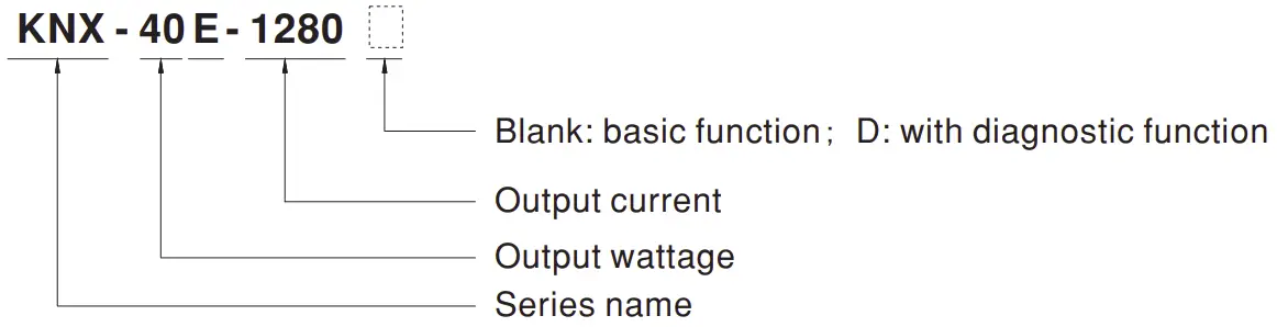
Model Encoding
Type | Function | Note |
Blank | 1280mA KNX Power Supply | In Stock |
D | 1280mA KNX Power Supply with Diagnostic function | In Stock |
Applications

- Intelligent home control
- Modern building automation
- Lighting control
- HV AC system
- Security system
- Blinds and shutters
- Monitoring systems
- Energy management
- Alarm monitoring
GTIN CODE
MW Search: https://www.meanwell.com/serviceGTIN.aspx
SPECIFICATION
| MODEL | KN-X 40E-12800 | |
|
OUTPUT | BUS OUTPUTVOLTAGE WITH CHOKE | Bus,30V (KNX black/red terminal block) |
| DC OUTPUT VOLTAGE WITHOUT CHOKE | 30V(Additional output for ancillary power) | |
| RATED CURRENT | 1280mA | |
| RATED POWER | 38.4W | |
| RIPPLE &NOISE/max.) Note2 | 100mVp-p | |
| SHORT CIRCUIT CURRENT | 2.8A | |
| SETUP, RISETIME | 1OOOms, 50ms/230VAC a t full load | |
| ACMAINS FAILURE BACK-UPTIME (Typ.) | 200ms/230VAC a t full load | |
|
INPUT | VOLTAGE RANGE | 180-264VAC 176- 280VDC |
| FREQUENCYRANGE | 47 -63Hz | |
| EFFICIENCY (Typ.) Note.3 | 86% | |
| AC CURRENT{Typ.) | 0.5A/230VAC | |
| INRUSH CURRENT (Typ.) | COLDSTART 60A(twidth=1200µsmeasured at 50%Ipeak)/230VAC | |
| LEAKAGE CURRENT | <1mA / 240VAC | |
|
PROTECTION | OVERLOAD | 205- 235% rated output power |
| Protection type: Constant current limiting, recovers automatically after fault condition is removed | ||
| OVER VOLTAGE | 33- 35V | |
| Protection type: Hiccup mode, recovers automatically after fault condition is removed | ||
|
FUNCTION | RESET | Physical button for the bus reset: Blank type: Press the RESET button for at least 20 seconds to reset the KNX Bus D type: Press the RESET button once, it will reset the KNX Bus last for 20seconds automatically |
| LED INDICATORS | Please refer to the “Explanation of LED Status· | |
| CHOKE | One Integrated choke | |
|
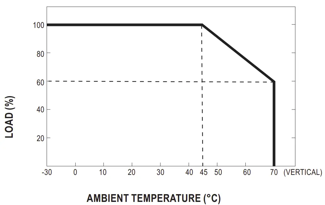
ENVIRONMENT | WORKING TEMP. | -30- +70°C(Refer to “Derating Curve; |
| WORKING HUMIDITY | 20- 95%RHnon-condensnig | |
| STORAGE TEMP,.HUMIDITY | -40- +ss•c, 10- 95% RH non-condensing | |
| VIBRATION TYPE OF PROTECTION | 10 – 500Hz, 2G10min./1cycle, 60mni . each along X,Y,Z axes | |
| TYPE OF PROTECTION | IP20design | |
| OVER VOLTAGE CATEGORY | III According to BS EN/EN61558, BS EN/EN50178,altitudeup to 2000 meters | |
| SAFETY & EMC (Note 4) | SAFETY STANDARDS | BSEN/EN65158-1,BSEN/EN61558-2-16; BS EN/EN50491-3approved |
| WITHSTAND VOLTAGE | I/P-0 /P:4 2KVAC I/P-FG:2KVAC | |
| ISOLATION RESISTANCE | I/-P 0/P, I/P-FG:100MOhms/ SOOVDC / 25°C/ 70%RH | |
| EMC EMISSION | Compliance to BS EN/EN50491-5-2,-5-3;BSEN/EN61000-3-2,-3-3 | |
| EMC IMMUNITY | Compliance to BS ENIEN50491-52- ,-5-3; BSEN/EN60100-4-2,3.4,5,6,8,11h,eavyindustrylevel | |
|
OTHERS | MTBF | 1414.2K hrs min. Telcordia SR-332(Beltcore) 217.1Khrsmin. MIL-HDBK-217F(25°C) |
| DIMENSION | 72’90’57mm (W’ H’ D) | |
| MOUNTING | 35mm mounting rail according to DIN BSEN/EN60715 | |
| PACKING | 0. 328Kg ; 48pcs/16.4Kg11.02CUFT | |
| NOTE |
| |
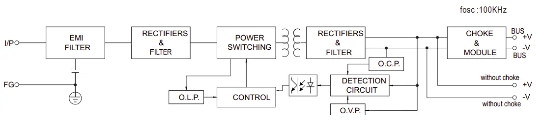
Block Diagram
Derating Curve
Static Characteristics
Mechanical Specification
Blank-Type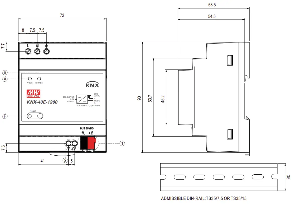
| 1 | KNX bus terminal (Red: +, DARK-GRAY:-) |
| 2 | Ancillary power termnials |
D-Type

| 1 | KNX bus terminal (Red: +, DARK-GRAY:-) |
| 2 | Ancillary power termnials |
Explanation of LED Status
Number | LED light | Color, Indicate type | Explanation / Range |
| A | Bus voltage V BUS | Green, constant | KNX Bus voltage is 28~31VDC |
| Red, constant | KNX Bus voltage lower than 28VDC | ||
| Orange, constant | KNX Bus voltage higher than 31VDC | ||
|
B |
Output current I OUT | Green, constant | Output current < 1280mA |
| Orange, constant | Output current is 1280mA~1600mA | ||
| Red, constant | Output current >1600 mA (Overload) | ||
|
C |
Power Input V IN | Green, constant | Powered by AC input |
| Green, flash | Powered by DC input | ||
| Red, constant | AC/DC input fail | ||
| D | Internal Temperature | Green, constant | Internal Temperature is 0~75 °C |
| Red, constant | Internal Temperature is out of this range | ||
| E | Telegram traffic | Green, flash | Telegram load < 80 % |
| Red, constant | Telegram load >= 80 % | ||
| F | KNX Reset | Red, constant | Device is during a KNX bus restart |
| G | Programming | Red, constant | Device in Program mode |
Note: Application data base needs to be downloaded into KNX-40E-1280D for the LED indicator to work properly.
Configuration and Commissioning
The application program(database) can be downloaded via Online Catalogs from ETS or via http://www.meanwell.com/productCatalog.aspx
Communication Object Table (Only for KNX-40E-1280D)
| Num | Object name | Object function | Length | DPT | Priority | Flag |
| 1 | Heartbeat | Send info | 1bit | 1.017,trigger | Low | CRT |
| 2 | Power supply on | Send info | 1bit | 1.017, trigger | Low | CRT |
| 3 | Send measurements | Request all measurements value | 1bit | 1.001,switch | Low | CW |
| 4 | Clear all data | Reset all calculation data | 1bit | 1.001,switch | Low | CW |
| 5 | Send calculations | Request all calculations value | 1bit | 1.001,switch | Low | CW |
| 6 | Bus reset | Request bus reset | 1bit | 1.001,switch | Low | CWU |
| 7 | Total working time | Send current total working time value | 4byte | 13.100,time lag,(s) | Low | CRT |
| 8 | Time from last startup | Send operating time from last startup | 4byte | 13.100,time lag,(s) | Low | CRT |
| 9 | The number of bus restart times | Send bus reset times value | 2byte | 7.001,pulses | Low | CRT |
| 10 | The number of device startup times | Send device startup times value | 2byte | 7.001,pulses | Low | CRT |
| 11 | Output voltage measured | Send voltage value measured | 2byte | 9.20,voltage,(mV) | Low | CRT |
| 4byte | 14.027,electric potential,(V) | Low | CRT | |||
| 12 | Output voltage alarm | Send threshold status | 1bit | 1.005,alarm | Low | CRT |
| 13 | Output current measured | Send current value measured | 2byte | 7.012,current,(mA) | Low | CRT |
| 2byte | 9.021,current,(mA) | Low | CRT | |||
| 4byte | 14.019,electric current,(A) | Low | CRT | |||
| 14 | Output current alarm | Send threshold status | 1bit | 1.005,alarm | Low | CRT |
| 15 | Device temperature measured | Send temperature value measured | 2byte | 9.001,temperature,(°C) | Low | CRT |
| 16 | Device temperature alarm | Send threshold status | 1bit | 1.005,alarm | Low | CRT |
| 17 | Maximum output current during tracking period | Send maximum value captured | 2byte | 7.012,current,(mA) | Low | CRT |
| 2byte | 9.021,current,(mA) | Low | CRT | |||
| 4byte | 14.019,electric current,(A) | Low | CRT | |||
| 18 | Maximum device temperature during tracking period | Send maximum value captured | 2byte | 9.001,temperature,(°C) | Low | CRT |
| 19 | Busload measured | Send busload value calculated | 1byte | 5.004,percentage,(0~255%) | Low | CRT |
| 20 | Busload alarm | Send threshold status | 1bit | 1.005,alarm | Low | CRT |
| 21 | The number of overload times | Send times count value | 2byte | 7.001,pulses | Low | CRT |
| 22 | Overload duration | Send duration time value | 4byte | 13.100,time lag,(s) | Low | CRT |
| 23 | The number of short circuits times | Send times count value | 2byte | 7.001,pulses | Low | CRT |
| 24 | Time load detached | Send duration time value | 4byte | 13.100,time lag,(s) | Low | CRT |
| 25 | Alarm 1 | Send threshold status | 1bit | 1.005,alarm | Low | CRT |
| 26 | Count 1 | Send times count value | 2byte | 7.001,pulses | Low | CRT |
| 27 | Duration 1 | Send duration time value | 4byte | 13.100,time lag,(s) | Low | CRT |
| 28 | Alarm 2 | Send threshold status | 1bit | 1.005,alarm | Low | CRT |
| 29 | Count 2 | Send times count value | 2byte | 7.001,pulses | Low | CRT |
| 30 | Duration 2 | Send duration time value | 4byte | 13.100,time lag,(s) | Low | CRT |
| 31 | Alarm 3 | Send threshold status | 1bit | 1.005,alarm | Low | CRT |
| 32 | Count 3 | Send times count value | 2byte | 7.001,pulses | Low | CRT |
| 33 | Duration 3 | Send duration time value | 4byte | 13.100,time lag,(s) | Low | CRT |
| 34 | Alarm 4 | Send threshold status | 1bit | 1.005,alarm | Low | CRT |
| 35 | Count 4 | Send times count value | 2byte | 7.001,pulses | Low | CRT |
| 36 | Duration 4 | Send duration time value | 4byte | 13.100,time lag,(s) | Low | CRT |
The priority of the particular communication objects as well as the flags can be adjusted. The flag control the function of the objects in the programming where C stands for communication, R for Read, W for write, T for transmit and U for update.
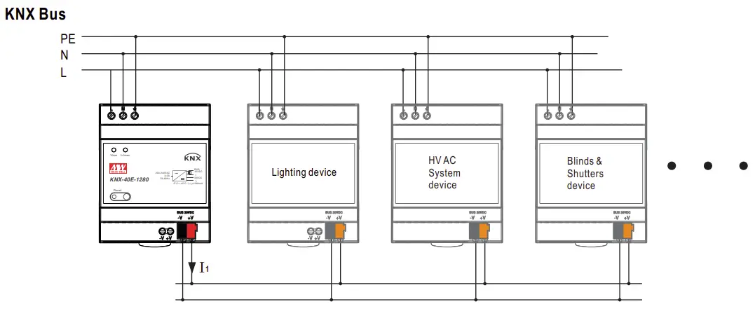
Typical application
Application 1: Powering KNX Bus Only
Bus wiring consideration:
- the maximum number of bus devices connected is 256 for TP1-256
- the maximum length of a line segment is 350 m, measured along the line between the power supply and the furthest device
- the maximum distance between two bus devices cannot exceed 700
- the maximum length of a bus line is 1000 m, keeping into account all segments.
Application 2:Powering KNX Bus and KNX device
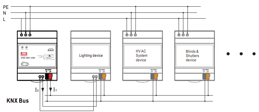
Note:
- Use only ancillary output of KNX-40E-1280 to power the KNX device
- The total current + should be equal or less than 1280mA. + ≤1280mA
- The above Bus wiring consideration is still applicable
Recommended Screwdriver, Wire and Torque Setting
- Screwdriver(Width*Thick):Slotted screwdriver 2.5*0.4~3.5*0.6
- Wire:0.5~4.0mm solid core or 0.5~2.5mm finely stranded
- Torque:0.8Nm
Installation Manual
Please refer to : http://www.meanwell.com/manual.html