
HARVEST TECHNOLOGY 442P 55 Gallon Preservative Applicator Instruction Manual
Introduction
Thank you for purchasing a Harvest Tec Model 442P Hay Preservative Applicator. Please read this manual carefully to ensure correct steps are followed to attach the applicator to the baler. This applicator is designed to apply Harvest Tec buffered acid. The model 442P Kit includes the following parts: tank, frame, pump, gauge, hose, electronic control box, and miscellaneous hardware. If you are unsure about your kit, contact your local dealer for specifications. For your convenience parts break downs are included in the back of this manual.
Left and Right sides are determined by facing in the direction of forward travel.
Tools Needed
- SAE wrench set
- Standard screw driver
- Crescent wrench
- Side cutter
- Metric socket set
- Hose cutter
- Hammer
- Measuring tape
- SAE socket set
- Drill bit set
- Center punch
Installation of Applicator
Tank and Saddle Installation
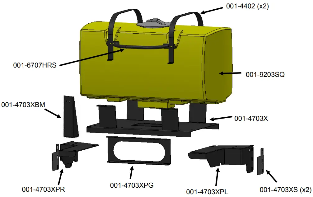
- Locate the left saddle leg, 001-4703XPL, and mount to the left side of baler. Locate one leg shim bracket, 001-4703XS, and place in between the leg and side of the baler. Use three 1/2″ x 1-1/4” hex bolts, 1/2″ lock washers, and two 1/2″ flat washers. Do not fully tighten.
- Locate the right saddle leg, 001-4703XPR, and mount to the right side of baler. Locate one leg shim bracket, 001-4703XS, and place in between the leg and side of the baler. Use three 1/2″ x 1-1/4” hex bolts, 1/2″ lock washers, and two 1/2″ flat washers. Do not fully tighten.
- Tighten the hardware attaching the saddle legs, 001-4703XPL & 001-4703XPR, and legs shims, 001- 4703XS, to the side sheets of the baler.
- Install the tank assembly (tank, straps, handrail, and saddle pan) on the legs. Secure the saddle pan, 001-
4703X, to the saddle legs with 1/2″ flat washer, 1/2″ lock washer, and 1/2″ hex nut from the bottom side in four locations. Tighten hardware. - Locate the tank support bracket, 001-4703XPG, and mount between the bottom of the saddle pan, 001- 4703X, and the sheet metal covering the air tank using two 3/8″ x 1” hex bolts, 3/8″ lock washers, 3/8″ flat washers and 3/8” nuts.
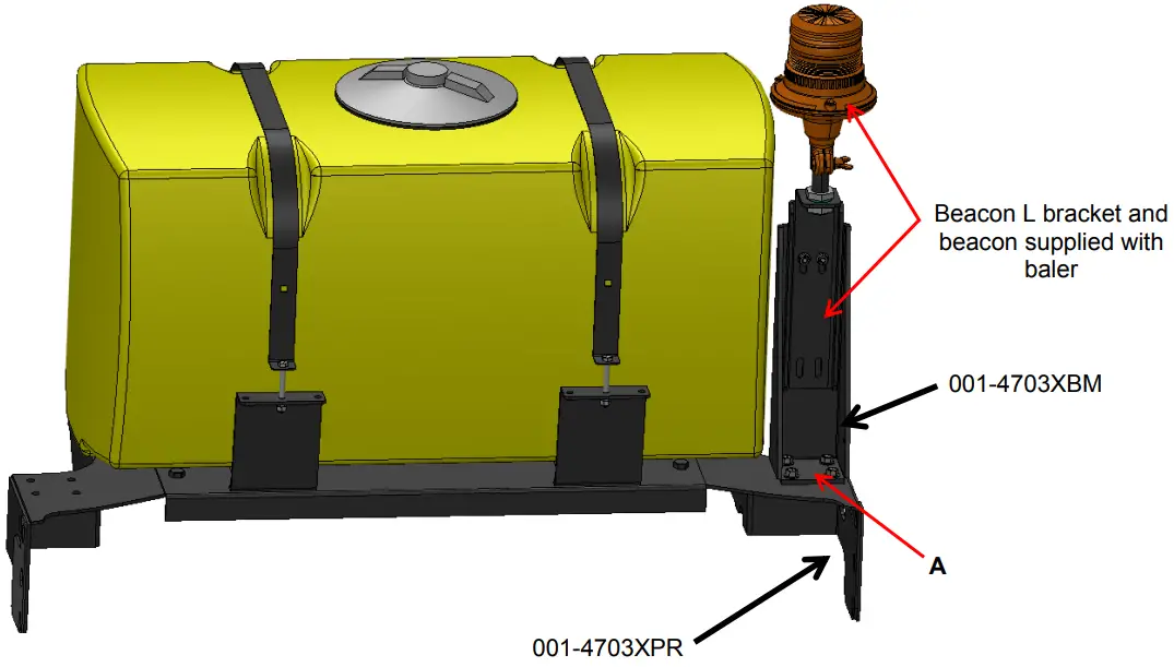
- Locate the beacon bracket, 001-4703XBM, and attach to the top of the right saddle leg, 001-4703XPR, using four 3/8″ x 1” hex bolts, 3/8” flat washers, 3/8” lock washers, and 3/8” hex nuts.


Installation of Optional Beacon
- Bolt beacon L-Bracket to beacon support (001-4703XBM) using two 5/16” x ¾” bolts and 5/16” flange nuts.
- Secure beacon support to top of right saddle leg (001-4703XPR) at point A using four 3/8” x 1” hex bolts and flange nuts.

Installation of Pump Manifold
Mounting Front Pump Plate Support
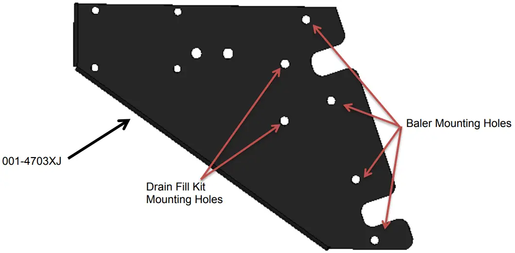
- Mount the Pump Mounting Bracket (001-4703XJ) to the angled support tube with two 5/16” x 1” hex bolts, flats, locks, and nuts. Use the specified mounting holes as shown in the figure above.
- Locate the two holes near the middle of the angled support on the mounting bracket that the drain/fill bracket lines up with and attaches to. Remove the existing nuts and install the drain/fill bracket. Reinstall the original nuts or those supplied with this kit to secure the drain/fill bracket to the baler.
- Locate parts bag 1. Thread 3/4” elbow fitting into the end of the tank (003-EL3434). Run 3/4″ hose from the elbow down the frame to the bottom of the baler. Connect valve assembly to the other end of hose. Place hose clamps on both ends and secure with zip ties.
Installation of Electronic Pump Assembly
Install the electronic pump assembly by placing the four pump bolts through 001-4703XJ and securing on the backside with 1/4” nuts (x4)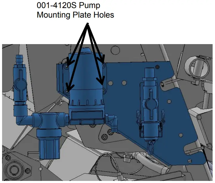
Installation of Drain / Fill Kit
Locate parts bag 1. Thread 3/4″ elbow fitting (003-EL3434) into end of tank. Run 3/4″ hose from the elbow down the frame to the bottom of the baler. Locate the two holes on the baler’s angled support bracket that line up with the holes in the valve bracket and attach using two 5/16” x1” self-tapping screws and secure with two 5/16” flange nuts. Connect valve assembly to other end of hose. Place hose clamps on both ends. Install supplied safety decals (DCL-8001 & DCL-8005) next to the ball valve assembly.
Secure hose to frame using cable locks.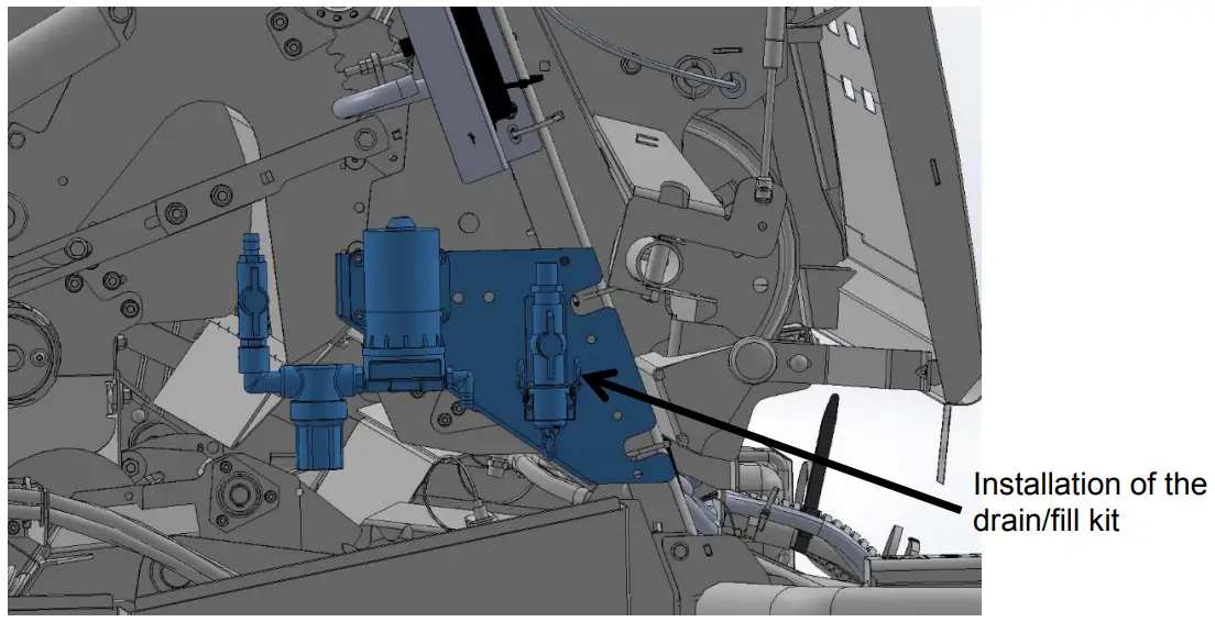
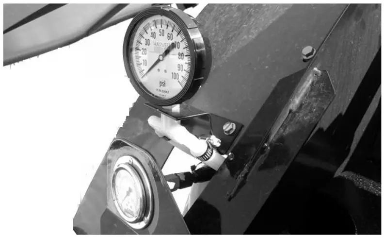
Installation of Gauge and Hose Manifold
- Drill two 3/8” holes and mount pressure gauge to sheet metal. Bend the gauge bracket to adjust the angle.
- Secure with two 5/16” x 1” flange bolts and flange nuts.

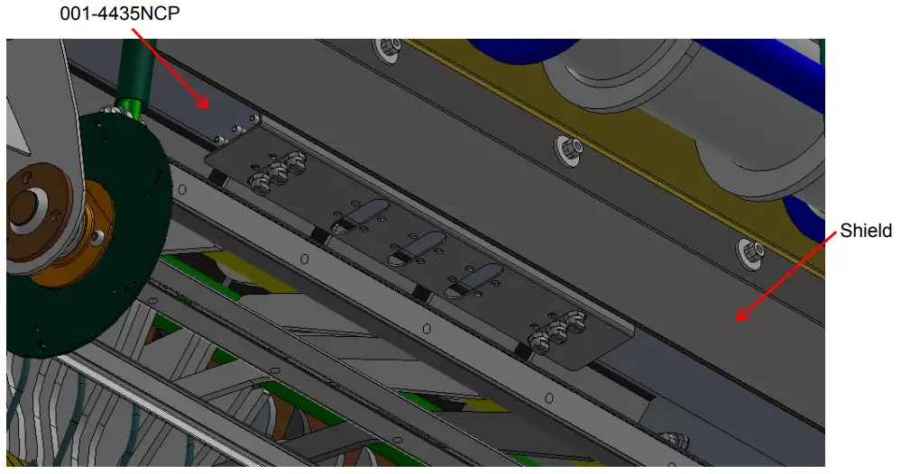
Placement of Spray Nozzle Assembly
- Locate the shield under the frame.
- Position the spray shield support (001-4435NCP) behind the shield with the formed flange to the rear.
- Attach spray shield support to baler frame with one 3/8” x 1” bolt, lock washer, and nut on each side.
- Insert pins of spray shield assembly into support and secure with two quick clips.
- Adjust spray direction by swiveling spray shield support. Tighten.

Refer to Tip Output under APPLICATION RATE of the control unit to calibrate system.
Installation of Plumbing
Tank to Pump
- Thread elbow (003-EL3412) into the bottom of the tank.
- Route 1/2” hose from bottom of tank through gap in sheet metal surrounding the baler gauge down to valve on pump intake.
- Secure with hose clamps.
Pump to Gauge
- Attach 1/2” hose to pump discharge and route up to gauge. Secure with hose clamps
Gauge to Nozzles
- Attach 1/2” hose to open port of gauge and route hose down to check valve of spray nozzle assembly.
- Attach quick disconnect (003-A1412 and 004-1207H).
- Secure with hose clamps.
Secure loose hoses to baler with supplied Jiffy clips. Use existing hardware to attach to baler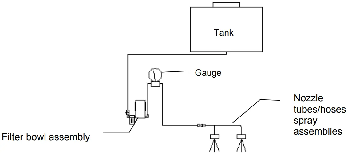
Installation of Controls and Routing the Wire Harnesses
- Locate the control in an area that allows operation for adjusting or turning the controls while operating the baler.
- Route the wire to the starter solenoid on all 12V tractors. Connect the green lead marked + to the hot terminal on the starter. Connect the black lead to a good ground. Do not reverse the leads. Be sure to use a voltmeter to verify that you do have 12 volts running to the box.
Note: For tractors with 24v starters, connect the power leads to the tractor’s right-hand battery. Do not connect the leads to the starter. Connect the lead marked + to the positive battery terminal and the lead marked- to the negative on the battery. Wiring connections to the battery normally results in corrosion; terminal coating is recommended.
- Attach the wire from the pump to the battery
- Run wire with molded black plug to back of tractor
- Run wire from pump up draw bar and connect it to the mating plug from the control box. Secure wire to baler with supplied cable ties.
Caution: Do not run a pump or use an electronic control box directly off a battery charger. For stationary use, the applicator can be connected to a new battery and the battery connected to a charge.
Parts Breakdown for the Tank and Saddle
Harvest Tec Model 442P Base Kit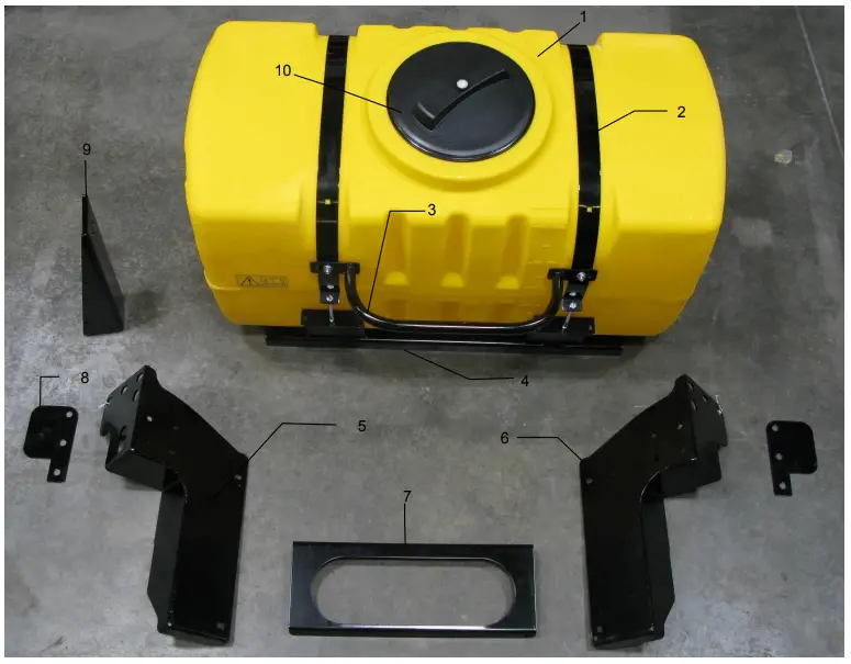
| Ref | Description | Part # | Qty |
| 1 | 50 Gallon tank | 030-9203SQ | 1 |
| 2 | Tank Strap | 001-4402 | 2 |
| 3 | Hand Rail | 001-6707HRS | 1 |
| 4 | Saddle | 001-4703X | 1 |
| 5 | Left Tank Leg | 001-4703XPL | 1 |
| 6 | Right Tank Leg | 001-4703XPR | 1 |
| 7 | Tank Support | 001-4703XPG | 1 |
| 8 | Leg Shim | 001-4703XS | 2 |
| 9 | Beacon Bracket | 001-4703XBM | 1 |
| 10 | Tank Cap and Gasket | 005-9022H | 1 |
Parts Breakdown for Control Box and Drain Fill Kit
Model 457 Control Box
| Ref | Description | Part # | Qty |
| 1 | Speed dial | 006-2022A | 1 |
| 2 | U-bracket | 001-2012E | 2 |
| 3 | Control box knob | 008-0923 | 1 |
| 4 | Control box enclosure | 006-2015A | 1 |
| 5 | Control box cove | 006-2015B | 1 |
| 6 | Pump lead | 006-4583 | 1 |
| 7 | Box Plug Pre-Serial # 4549 | 006-4581 | 1 |
| 8 | Power lead Pre-Serial # 4549 | 006-4580C | 2 |
| 9 | Power lead After Serial # 4550 | 006-4580M | 1 |
| 10 | Box Plug After Serial # 4550 | 006-4581M | 1 |
Parts Breakdown for Drain Fill (Model 442P)
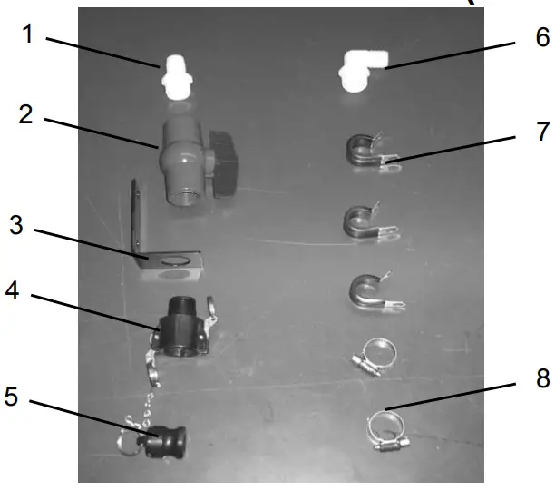
| Ref | Description | Part # | Qty |
| 1 | Straight fitting | 003-A3434 | 1 |
| 2 | Ball valve | 002-2200 | 1 |
| 3 | Valve holder | 001-6702H | 1 |
| 4 | Female couple | 002-2204A | 1 |
| 5 | Male coupler | 002-2205G | 1 |
| 6 | Elbow | 003-EL3434 | 1 |
| 7 | Jiffy clip | 008-9010 | 3 |
| 8 | Hose clamp | 003-9004 | 2 |
| NP | 3/4” Hose | 002-9002 | 10ft |
Parts Breakdown Model Specific Installation Kits
Harvest Tec Model 442P Installation Kit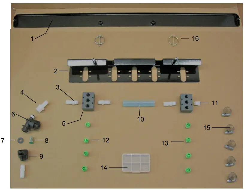
| Ref | Description | Part # | Qty |
| 1 | Spray Sheild Holder | 001-4435NCP | 1 |
| 2 | Spray Sheild | 001-4435NSX | 1 |
| 3 | 1/4″ x 1/2″ Straight Fitting | 003-A1412 | 4 |
| 4 | 1/4″ x 1/2″ | 003-A1412F | 1 |
| 5 | Spray Shield Manifold | 001-4435NSB | 2 |
| 6 | Diaphram Check Valve | 004-1207H | 1 |
| 7 | Washer | 004-1207W | 1 |
| 8 | Tip Striner | 004-1203-100 | 1 |
| 9 | Female Disconnect 1/4” | 004-1207H | 1 |
| 10 | Eva Tubing 1/2″ | 002-9002 | 4 |
| 11 | Hex Plug 1/4″ | 003-F14 | 1 |
| 12 | Tip – Green | 004-T8004-PT | 2 |
| 13 | Tip – Green | 004-T8008-PT | 2 |
| 14 | Mini Plano Box | 008-9001 | 1 |
| 15 | Hose Clamp | 003-9003 | 5 |
| 16 | Pin Lynch 3/16 | 008-4576 | 2 |
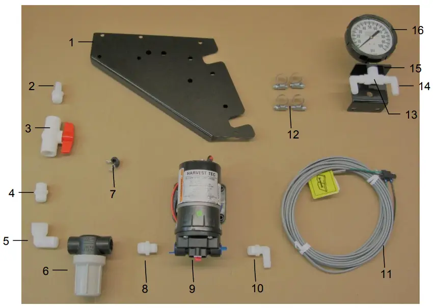
| Ref | Description | Part # | Qty |
| 1 | Pump Bracket | 001-4703XJ | 1 |
| 2 | 1/2” Fitting | 003-A1212 | 1 |
| 3 | Ball Valve | 002-2212 | 1 |
| 4 | 1/2” Nipple | 003-M1212 | 1 |
| 5 | Elbow 1/2” | 003-SE12 | 1 |
| 6 | Filter Bowl Assembly | 002-4315-80 | 1 |
| 7 | Pad Jiffy Clip 1/4” | 008-9011 | 1 |
| 8 | Nipple 3/8-1/2 | 003-M1238 | 1 |
| 9 | Pump | 007-4120S | 1 |
| 10 | Elbow | 003-EL3812 | 1 |
| 11 | Harness Pump Lead 26ft | 006-4574 | 1 |
| 12 | Hose Clamp | 003-9003 | 4 |
| 13 | Tee 1/4″ | 003-TT14 | 1 |
| 14 | Elbow Fitting 1/4” x 1/2″ | 003-EL1412 | 1 |
| 15 | Gauge Holder | 001-4717 | 1 |
| 16 | Gauge 4” | 002-2208Z | 1 |
Warranty
Harvest Tec, LLC. Warranty and Liability Agreement
Harvest Tec, LLC. will repair or replace components that are found to be defective within 12 months from the date of manufacture. Under no circumstances does this warranty cover any components which in the opinion of Harvest Tec, LLC. have been subjected to negligent use, misuse, alteration, accident, or if repairs have been made with parts other than those manufactured and obtainable from Harvest Tec, LLC.
Our obligation under this warranty is limited to repairing or replacing free of charge to the original purchaser any part that in our judgment shows evidence of defective or improper workmanship, provided the part is returned to Harvest Tec, LLC. within 30 days of the failure. If it is determined that a non-Harvest Tec branded hay preservative has been used inside the Harvest Tec applicator system where the failure occurred, then Harvest Tec reserves the right to deny the warranty request at their discretion. Parts must be returned through the selling dealer and distributor, transportation charges prepaid.
This warranty shall not be interpreted to render Harvest Tec, LLC. liable for injury or damages of any kind, direct, consequential, or contingent, to persons or property. Furthermore, this warranty does not extend to loss of crop, losses caused by delays or any expense prospective profits or for any other reason. Harvest Tec, LLC. shall not be liable for any recovery greater in amount than the cost or repair of defects in workmanship.
There are no warranties, either expressed or implied, of merchant ability or fitness for particular purpose intended or fitness for any other reason.
This warranty cannot guarantee that existing conditions beyond the control of Harvest Tec, LLC. will not affect our ability to obtain materials or manufacture necessary replacement parts.
Harvest Tec, LLC. reserves the right to make design changes, improve design, or change specifications, at any time without any contingent obligation to purchasers of machines and parts previously sold.
Revised 4/17
DECLARATION OF INCORPORATION

MANUFACTURER:
Harvest Tec LLC.
2821 Harvey St.
P.O. Box 63
Hudson, WI 54016, U.S.A.
REPRESENTATIVE ESTABLISHED IN COMMUNITY:
Profitable Farming Company
Middle Barlington, Roborough
Winkleigh, Devon, EX19 8AG
ENGLAND
The person above certifies and declares that:
VIRTUAL MACHINE: Equipment mounted on a farm press and for the application of inoculations onto
forage crops.
MODEL: 442P-21-INST-Imp&Metric
BRAND: Harvest Tec
SERIAL NUMBER:
This application preservatives for hay Harvest Tec system meets the Directive 2006/42/EC of the
European Parliament and the Council of 17 May 2006 and other applicable European Directives including Directive 2004/108/EC on the Electromagnetic comparability
The application of preservatives for hay Harvest Tec system will be turned on after being installed on a farm press has been declard in conformity with the Machinery Directive.
Person in the community authorized to provide information on the partly completed machinery and making this statement:
Richard Snell, President, Profitable Farming Company
Signed on May 21, 2011: Middle Barlington, Roborough Winkleigh, Devon, EX19 8AG
Support
HARVEST TEC, LLC.
P.O. BOX 63
2821 HARVEY STREET
HUDSON, WI 54016
PHONE: 715-386-9100
1-800-635-7468
FAX: 715-381-1792
Email: [email protected]


