HARVEST TECHNOLOGY 438K 25 Gallon Electronic Preservative Applicators

Introduction
Congratulations on and thank you for purchasing a Harvest Tec Model 438K applicator. Please read this manual carefully to ensure correct steps are followed to attach the applicator to the baler. This applicator is designed to apply Harvest Tec buffered acid. Use of alternative products may cause complications. Including inaccurate readings from the flow meter and damage to all parts. Resulting in the warranty being void. For your convenience we have included a parts break down for the model 438K applicator. If something goes wrong bring this manual into the dealer so they can order the correct parts for you. Ordering the correct part number is very important. It will save you time, money, and your crop. This applicator is crop eye compatible (Nov. 2003 and newer.) For your convenience we have included a parts break down in the back of this manual.
Left and Right sides are determined by facing in the direction of forward travel.
Tools Needed
- SAE wrench set
- Standard screw driver
- Crescent wrench
- 1-1/2” hole saw (4415 install only)
- Side cutter
- Hose cutter
- Hammer
- Measuring tape
- SAE socket set
- Drill bit set
- Center punch
- Metric socket set
Installation of Applicator
Installation of Mounting Brackets, Tank, and Drain / Fill Line
Locate the frame mount stiffener brackets (001-4704KS) and the left and right mounting brackets (001-4704KE & 001-4704KF) as seen in figure 1. Fasten one 001-4704KS to each the left and right mounting brackets at point A using two 3/8” x 1 1/4” bolts for each stiffener bracket.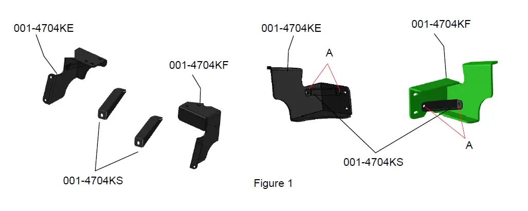
Secure the left and right mounting brackets (001-4704KE and 001-4704KF) to the baler frame at point B in figure 2 using the existing six bolts and nuts that bolt the tongue to the baler frame. Tighten all hardware. 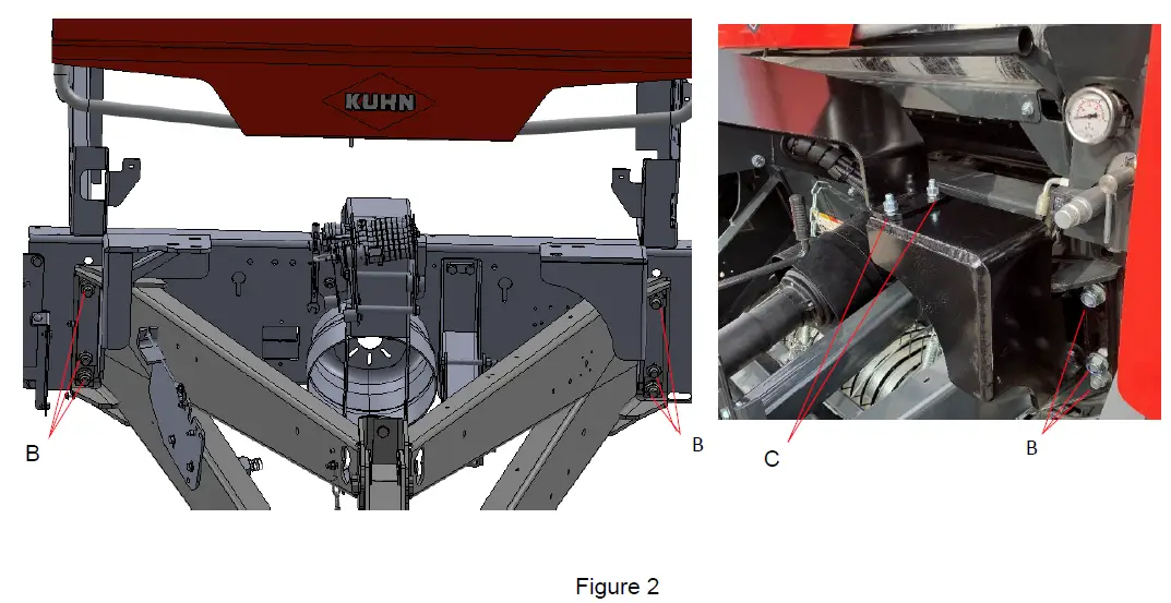
Locate the tank saddle U-bracket (001-4704KB) and line it up over the baler tongue so it matches up with the tank saddle legs (001-4704KE & 001-4704KF) at point C and D as shown in figure 3. Fasten 001-4704KB to the left saddle leg (001-4704KE) at point C using two 1/2” x 2” bolts, flats, locks, and nuts. Do the same with 001-4704KB to the right saddle leg (001-4704KF) at point D using two 1/2” x 2” bolts, flats, locks, and nuts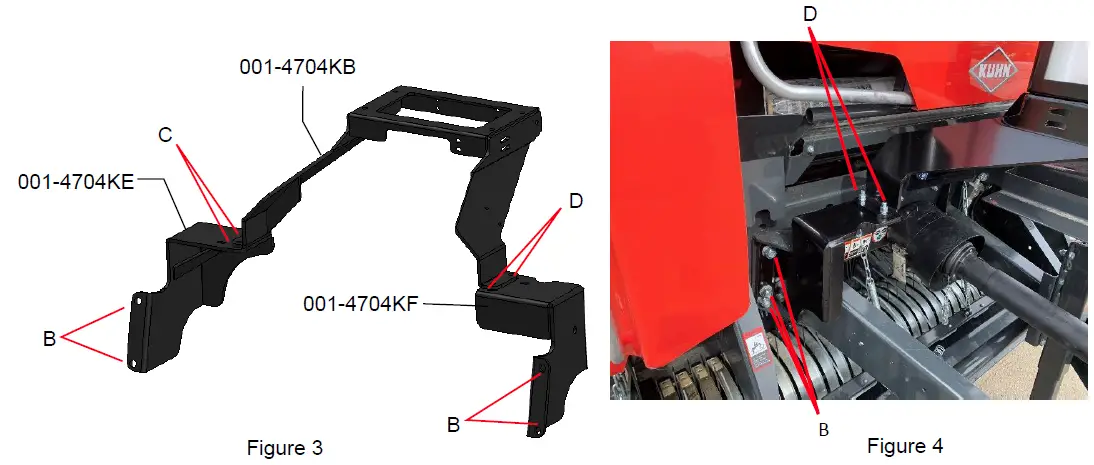
Locate the tank bracket (001-4704KA) as shown in figure 5. Fasten 001-4704KA to the tank saddle U-Bracket (001-4704KB) with four 1/2” x 1 ½ ” bolts, locks, flats, and nuts at the four corners at the bottom of 001-4704KA as shown at point E. Tank may need to be removed from the tank bracket (001-4704KA) to do this. The bolt heads and flat washers should be on the top. Locate the toolbox bracket (001-4704KJ) as shown in figure 6. Fasten 001-4704KJ to 001-4704KB with four 3/8” x 1 1/4” bolts, locks, flats, and nuts as shown at point F. 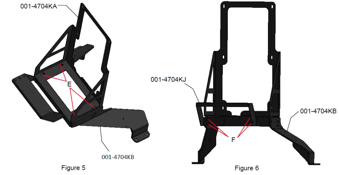
If your baler has a sidewind jack, complete the next steps. If your baler does not have a sidewind jack, skip to the tank installation on page 7.
Locate the jack bracket assembly (001-4704KM) and fasten it to the existing jack mounted on the baler shown at point G in figure 7 using two 1/2” x 4½” bolts, flats, locks, and nuts. Locate the support bracket (001-4704KG) and fasten it to the top hole on the jack bracket assembly (001-4704KM) shown at point H in figure 8 using a ½” x 1½” bolt, flat, lock and nut. You may have to cut off the end of the support bracket (001-4704KG) at the notch to fit the baler.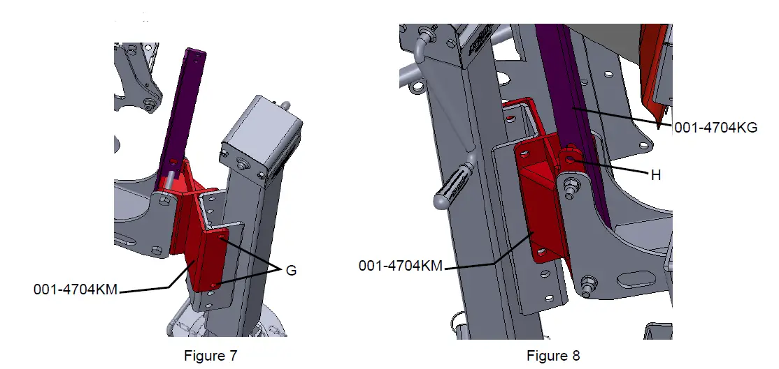
Locate the support bracket (001-4704KG) and fasten it to the inside of the U-Bracket (001-4704KB) shown at point I in Figure 9 below using two 3/8” x 1¼” bolts, flats, locks, and nuts. 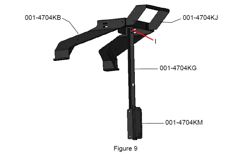
Note – removal of Kuhn factory tool box bracket is required. Remove and discard bracket. Relocate tool box to 001-4704KJ bracket. Locate the mounting bracket (001-4704KR) and fasten it to the outside of the U-Bracket (001-4704KB) shown at point J in figure 10 using 3/8” x 1 ¼” bolts, locks, flats, and nuts. Drill a 3/8” hole in the baler tongue and fasten 001-4704KR to the baler tongue using a 3/8” x 1 ¼” bolt, lock, flat, and nut.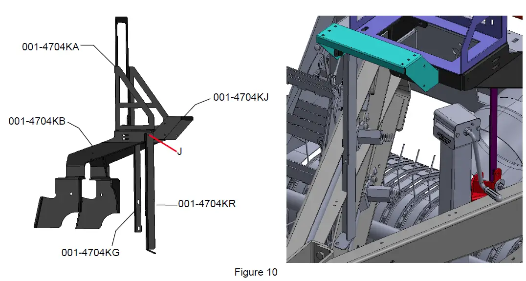
Locate the tank (005-4705T) as shown in figure 11 and fasten it to the tank bracket (001-4704KA) using six 5/16” x ¾” bolts, internal tooth lock washers, and flats. Tighten all hardware. 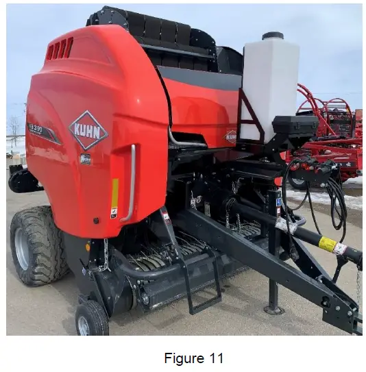
Locate the tank (005-4705T) as shown in figure 11 and fasten it to the tank bracket (001-4704KA) using six 5/16” x ¾” bolts, internal tooth lock washers, and flats. Tighten all hardware. 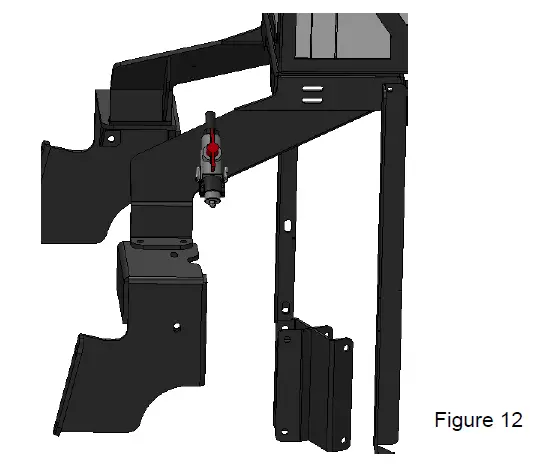
Mount Pump Plate Assembly
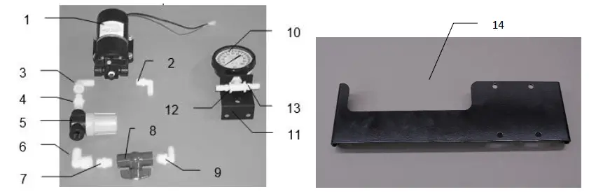
Use four 3/8” x 1-1/4” bolts, locks, and flat washers to mount the pump bracket (001-4704KL) with assembly, shown in figure 13, to the inside of the toolbox bracket (001-4704KJ) as shown in figure 14.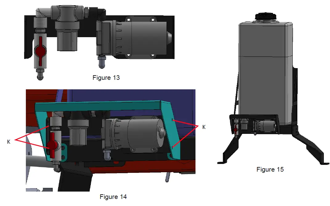
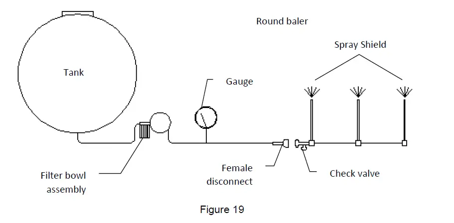
Installation of Gauge and Hose Manifold
Mount the gauge to the tank frame or the frame of the baler. If you mount the gauge to the baler, make sure it does not interfere with any of the baler’s operation, or be in an area where it could be tripped over when servicing the baler. Connect the hose between the pump and the gauge. Run the plumbing from the gauge to the check valve on the spray shield. Connect the disconnect to the end of the hose from the gauge and to the check valve. Secure to baler using the padded jiffy clips provided. Use hose clamps on all connections.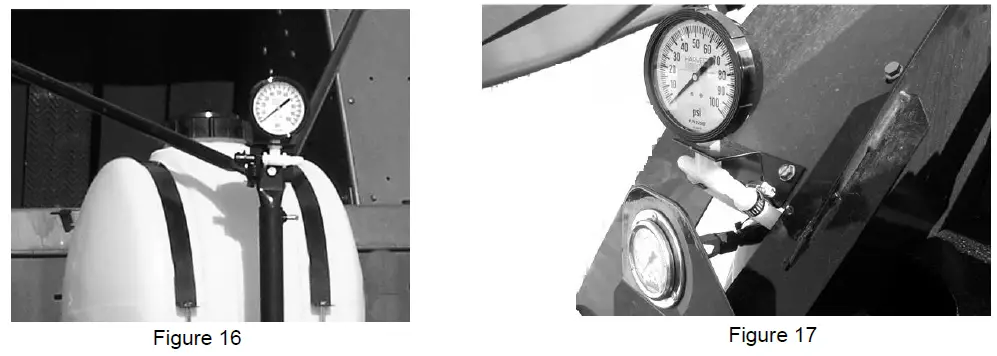
A. Drill two 3/8” holes and mount pressure gauge to sheet metal. Bend the gauge bracket to adjust the angle.
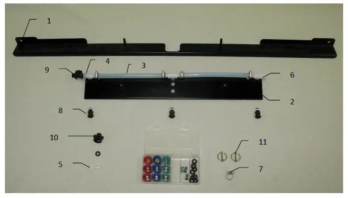
Placement of Spray Nozzle Assembly
Locate the spray shield holder (001-4704E2) and spray shield (001-4703GK). Center the spray shield holder over the rotor. Clamp the bracket and drill two 7/16” holes point F on figure 6. Secure the bracket using two 3/8 x 1 1/4 bolts, locks, flats, and nuts. Tighten all hardware. Install the shield and secure using the two lynch pins (008-4576).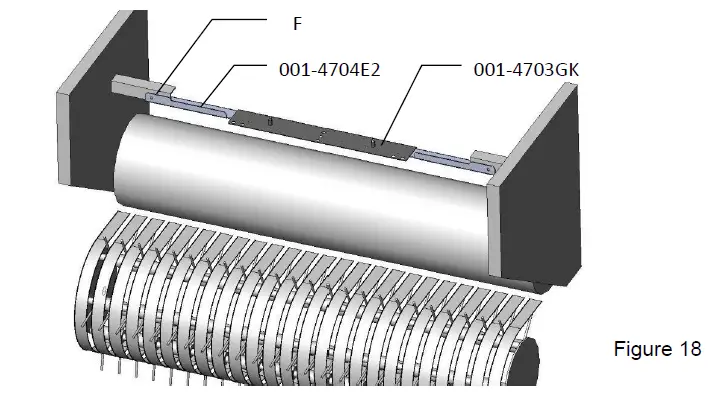
Installation of Plumbing
- Intake
Screw the 003-EL3412 (3/4” to 1/2” elbow) into the bottom of the tank. Then route the 002-9001(1/2” hose) from bottom of the tank to the ball valve. Secure with hose clamps. - Outlet round baler with 438K-SO
Run hose from the pump outlet to the gauge. The gauge is assembled with two straight fittings; an elbow is supplied in the parts bag to be used if necessary. From the gauge the hose will need to be run to the check valve on the spray shield. Cut the hose to length and attach the female disconnect and straight fitting. Attach these to the check valve using one washer.
Installation of Controls
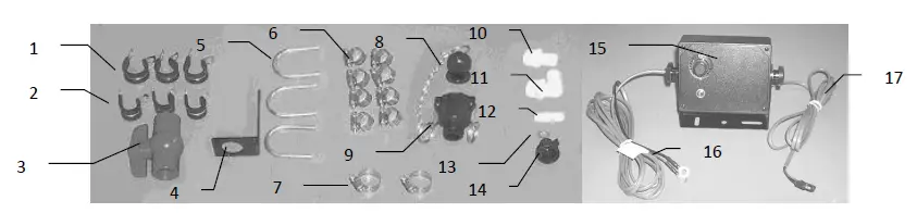
Locate parts bag 13.
Route the wire to the starter solenoid on all 12v tractors. Connect the green lead marked + to the hot terminal on the starter. Connect the black lead to a good ground. Do not reverse the leads. Be sure to use a voltmeter to verify that you do have 12 volts running to the box.
Note: For tractors with 24v starters, connect the power leads to the tractor’s right-hand battery. Do not connect the leads to the starter. Connect the lead marked + to the positive battery terminal and the lead marked- to the negative on the battery. Wiring connections to the battery normally results in corrosion; terminal coating is recommended.
Caution: Do not run a pump or use an electronic control box directly off a battery charger. For stationary use, the applicator can be connected to a new battery and the battery connected to a charger
Operation
The 438K applicator is very simple to operate. After installing the applicator, fill the tank with 5 gallons of water. With control box connected to the applicator and the power cord hooked to the 12-volt battery we can start the test. First flip on the toggle switch. You might hear the buzzing of the motor. Turn the dial on the control box until the gauge starts to climb. By turning the dial clockwise, the pressure will go up. By turning the dial counterclockwise, the pressure will decrease. With the applicator spraying at about 30 PSI, look for leaks at all the hose connections and fittings. Using water in this step instead of chemical will save you from wasting chemical and making a mess if leaks are found. When you are comfortable with the operation of the controls you can set the applicator to the amount of chemical you would like it to put on.
Message Light
The LED under the speed dial will be steady on when the applicator is running under normal situations. If the light blinks on and off use the below information for the message.
Slow steady on and off blink: The system is attached to hay indicators (474A) or a foot switch. This message means that the pump is paused. The light will come on constant once the baler is back in the windrow.
Two quick blinks: The pump motor or pump harness is shorted.
Three quick blinks: Pump motor is over the current limit (10 amps).
Four quick blinks: Power is under current from a bad connection.
The control box must have the on/off switch toggled to clear the message after the fault has been fixed to clear.
CALIBRATION
There are three things that you need to know when calibrating your applicator. First you need know how many tons per hour you bale. Second you need to know the rate, or how many pounds of product to apply for a given ton per hour. Finally, you need to know what tips to use and at what pressure to set the gauge.
DETERMINING TONS PER HOUR
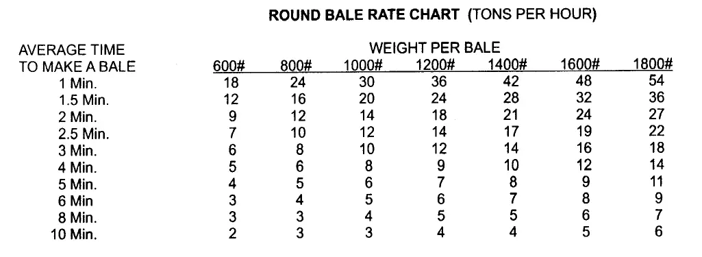
Round Balers
- Time 3 bales and average the time it takes to make a bale. Don’t include tying time.
- Estimate the weight of the bale.
- Use the bale rate chart below to determine the tons you are baling per hour.
Example: You made 3 round bales and it took you an average of 2 minutes a piece to bale each of them. Your baler’s operator manual tells you that an average bale made by your machine weighs 1000lb. (Remember if the hay is dry it will weigh less and if the hay is wet it will weigh more.) Using the chart on the following page, cross-reference 2 minutes with 1000lbs and you will come up with 14 ton per hour.
DETERMINE THE RATE OF CHEMICAL
The number of pounds of chemical required to be applied to a given ton of hay, depends on the moisture and the type of chemical used. The moisture of the hay is important in determining how much chemical to use. The wetter the hay the more product is needed, the dryer the hay the less product is needed. By knowing the moisture, you can make sure you are treating the hay correctly. Under applying will save money but spoilage most likely occurs. Over applying will waste money however, the hay will be saved. Some chemicals require more or less to treat the same amount of hay. To find the exact number of pounds required, for a given hay moisture, refer to the label on the drum or contact the manufacture. Harvest Tec applicators come with the red, green, and blue sets of tips. If your chemical requires rates other than what these tips deliver you will need to purchase them through your dealer.
CALIBRATION REMINDERS
- Watch the pressure gauge as the setting will vary with tractor’s electrical output, temperature and other factors.
- Check your application rate by measuring product used against actual tons baled.
REMEMBER, ONLY YOU CAN CONTROL HOW MUCH PRODUCT IS APPLIED AND THAT WILL DETERMINE IF YOUR HAY WILL KEEP!!!
SELECTING TIPS AND SETTING PRESSURE
Once you have determined your tons per hour and the amount of chemical needed for the moisture you are applying at, you can select your tips and determine your gauge settings.
- Multiply the tons per hour by the amount of chemical required for the moisture you are applying at. This sum will give you the application rate.
- Select the proper set of tips from the application rate chart and install them.
- For the tips you have selected, you will need to keep the gauge at the recommended PSI to achieve the proper application rate.
- Set the pressure by adjusting the dial on the control box and by reading the pressure of the gauge to match the desired rates. The numbers on the dial are for reference only. Rate is determined by watching the pressure gauge.
Example: You are baling at 12.5 tons per hour with your round baler. The moisture that you are baling at requires you to apply 8 pounds per ton. Multiply the 12.5 tons x 8lbs. = 100lbs per hour. Using the chart (lbs/hr) on the following page, you will notice the red set of tips at 35 PSI will give you that output.
GENERAL CALIBRATION CHART IN POUNDS PER HOUR
Use the following chart for all applications that require pounds measurements.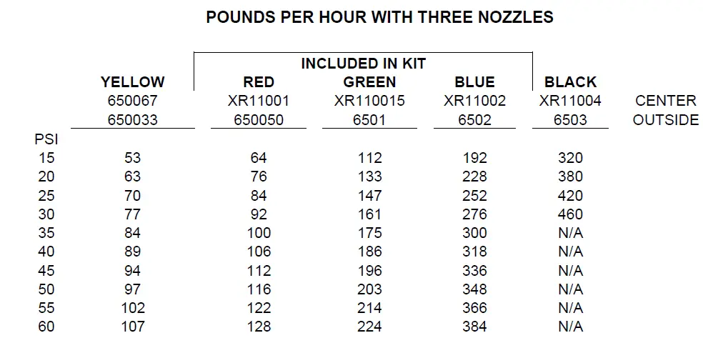
GENERAL CALIBRATION CHART IN GALLONS PER HOUR
Use the following chart for all applications that require volume measurements.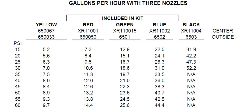
ROUTINE MAINTENANCE
- Clean the tip strainers and main strainer every 10 hours of operation or more frequently if required.
- Depending on the product being used, the system may need to be flushed with water at a regular interval (consult with manufacturer of the chemical.) If Harvest Tec product is being used, flushing is not necessary.
- Although the pump can run dry, extended operation of a dry pump will increase wear. Watch the preservative level in the tank.
- Cover the electronic cab control box on open station tractors if left outside.
- Pump performance may start to decline after 400 hours of use. Rebuilding the pump is a simple procedure if the motor is not damaged. Order pump rebuilding kit #007-4581.
- If you are using bacterial inoculants, flush out system daily after each use.
- Clean tank cap breather every 20 hrs or more frequently if required.
WINTER STORAGE
- Thoroughly flush the system with water.
- Remove the filter bowl and run dry until the water has cleared out of the intake side.
- Remove the red plug from the bottom of the pump, drain, and run the pump for 30 seconds or until it is dry.
- Drain all lines on the outlet side.
- Never use oils or alcohol based anti-freeze in the system.
- For spring start-up, or anytime the pump is frozen, turn off the power immediately to avoid burning the motor out. The pump head can be disassembled and freed or rebuilt in most cases.
TROUBLESHOOTING CHECKS
| PROBLEM | POSSIBLE CAUSE | SOLUTION |
| Pump will not run. | 1. Circuit breaker tripped on electronic unit. | 1. Check for short, low voltage, and reset breaker. |
| 2. Pump locked up. | 2. Clean or rebuild pump if motor is OK. | |
| 3. Damaged wire. | 3. Repair damaged wire. | |
| 4. Vapor locked. | 4. Loosen hose by check valve at spray shield and bleed air. | |
| Pump runs but will not prime. | 1. Air leak in intake. | 1. Tighten fittings on intake side. |
| 2. Clogged intake. | 2. Clean. | |
| 3. Restricted outlet. | 3. Check and clean tips. | |
| 4. Check valve on outlet stuck closed. | 4. Clean or repair check valve. | |
| 5. Dirt inside pump. | 5. Replace pump check valve. | |
| Pump does not develop enough output. | 1. Air leaks or clogs on inlet side. | 1. Tighten or clean filter bowl assembly. |
| 2. Electronic box out of adjustment. | 2. Refer to box adjustment page. | |
| 3. Pump worn or dirty. | 3. Rebuild pump. | |
| 4. Low supply voltage. (Pump requires 12v minimum) | 4. Check voltage at connection with voltmeter. | |
| 5. Bad gauge. | 5. Gauge should read less than 10 PSI when not in use. Also tips should lose spray pattern below 10 PSI. Check accuracy. | |
| Pump output varies. | 1. Clogged or restricted inlet. | 1. Clean |
| 2. Worn pump parts. | 2. Rebuild pump. | |
| Message light blinks two times | 1. Pump or wire harness shorted. | 1. Check harness running to pump and verify no shorts or problems. 2. Check to see if pump motor is locked up. Repair or replace. |
| Message light blinks three times | 1. Pump is drawing greater than 10 amps. | 1. Check to see if motor is running correctly. Repair or replace. |
| Message light blinks four times | 1. Undercurrent coming to control box. | 1. Check all battery connections and connections running up to control box. |
Model 438K Base Kit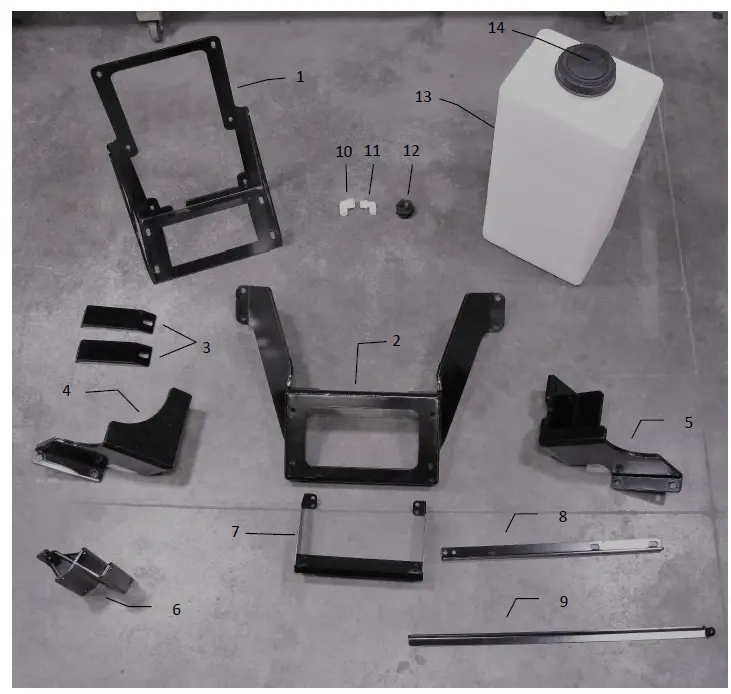
| Ref | Description | Part # | Qty | Ref | Description | Part # | Qty |
| 1 | Tank Bracket (V2) | 001-4704KA | 1 | 10 | Elbow | 003-EL3434 | 1 |
| 2 | U-Bracket (V2) | 001-4704KB | 1 | 11 | Street Elbow | 003-SE34 | 1 |
| 3 | Frame Mount Stiffener Bracket (V1) | 001-4704KS | 2 | 12 | Tank Fitting | 005-9100 | 2 |
| 4 | Mounting Bracket LH (V2) | 001-4704KE | 1 | 13 | 20 Gallon Tank | 005-4705T | 1 |
| 5 | Mounting Bracket RH (V2) | 001-4704KF | 1 | 14 | Tank Cap | 005-9022C | 1 |
| 6 | Jack Bracket Assembly (V1) | 001-4704KM | 1 | ||||
| 7 | Toolbox Bracket (V2) | 001-4704KJ | 1 | ||||
| 8 | Support Bracket (V1) | 001-4704KG | 1 | ||||
| 9 | Tank Mount Stiffener Bracket (V1) | 001-4704KR | 1 | Complete Kit | 030-0438K-TK | ||
| Ref | Description | Part # | Qty | Ref | Description | Part # | Qty |
| 1 | Pump | 007-4120S | 1 | 8 | Ball valve | 002-2212 | 1 |
| 2 | Elbow fitting | 003-EL3812 | 1 | 9 | Elbow fitting | 003-EL1212 | 1 |
| 3 | Street elbow | 003-SE38 | 1 | 10 | Gauge | 002-2208Z | 1 |
| 4 | Nipple fitting | 003-M1238 | 1 | 11 | Gauge bracket | 001-4717 | 1 |
| 5 | Filter bowl assembly | 002-4315 | 1 | 12 | Tee | 003-TT14 | 1 |
| 6 | Street elbow | 003-SE12 | 1 | 13 | Straight fitting | 003-A1412 | 2 |
| 7 | Nipple fitting | 003-M1212 | 1 | 14 | Pump Bracket | 001-4704KL | 1 |
MODEL 438K DRAIN/FILL KIT, & CONTROL BOX
| Ref | Description | Part # | Qty | Ref | Description | Part # | Qty |
| 1 | Jiffy clip-large | 008-9009 | 3 | 9 | Female coupler | 002-2204A | 1 |
| 2 | Jiffy clip-small | 008-9010 | 3 | 10 | Straight fitting | 003-A3434 | 1 |
| 3 | Ball valve | 002-2200 | 1 | 11 | Elbow fitting | 003-EL3434 | 1 |
| 4 | Valve bracket | 001-6702H | 1 | 12 | Straight fitting | 003-A1412 | 1 |
| 5 | U-bolt – small | 001-4714UBS | 2 | 13 | Washer | 004-1207W | 1 |
| U-bolt – large | 001-4714UBL | 1 | 14 | Female disconnect | 004-1207H | 1 | |
| 6 | Hose clamp | 003-9003 | 8 | 15 | Control box | 030-0457 | 1 |
| 7 | Hose clamp | 003-9004 | 2 | 16 | Power harness | 006-4580C | 1 |
| 8 | Male shut-off | 002-2205G | 1 | 17 | Pump harness | 006-4583 | 1 |
438K-SO INSTALLATION KIT 
| Ref | Description | Part # | Qty | Description | Part # | Qty |
| 1 | Shield bracket | 001-4704E2 | 1 | Tip Kit (Complete) | 030-9002 | 1 |
| 2 | Spray shield | 001-4703GK | 1 | Plastic Box | 008-9000 | 1 |
| 3 | Hose | 002-9001 | 3 | Red Cap | 004-1207B | 3 |
| 4 | Tee | 003-TT14 | 3 | Outside Tip (Red Set) | 004-650050-SS | 2 |
| 5 | Straight fitting | 003-A1412 | 5 | Inside Tip (Red Set) | 004-XR11001VS | 1 |
| 6 | Plug | 003-F14 | 1 | Green Cap | 004-1207A | 3 |
| 7 | Hose clamp | 003-9003 | 5 | Outside Tip (Green Set) | 004-6501-SS | 2 |
| 8 | Male quick fitting | 004-4710 | 3 | Inside Tip (Green Set) | 004-XR110015VS | 1 |
| 9 | Check valve | 004-1207V | 1 | Blue Cap | 004-1207C | 3 |
| 10 | Female disconnect | 004-1207H | 1 | Outside Tip (Blue Set) | 004-6502-SS | 2 |
| 11 | Lynch pin | 008-4576 | 2 | Inside Tip (Blue Set) | 004-XR11002VS | 1 |
| Tip strainer | 004-1203-100 | 3 | ||||
| Washer | 004-1207W | 9 |
Harvest Tec, LLC. Warranty and Liability Agreement.
Harvest Tec, LLC. will repair or replace components that are found to be defective within 12 months from the date of manufacture. Under no circumstances does this warranty cover any components which in the opinion of Harvest Tec, LLC. have been subjected to negligent use, misuse, alteration, accident, or if repairs have been made with parts other than those manufactured and obtainable from Harvest Tec, LLC.
Our obligation under this warranty is limited to repairing or replacing free of charge to the original purchaser any part that in our judgment shows evidence of defective or improper workmanship, provided the part is returned to Harvest Tec, LLC. within 30 days of the failure. Parts must be returned through the selling dealer and distributor, transportation charges prepaid.
This warranty shall not be interpreted to render Harvest Tec, LLC. liable for injury or damages of any kind, direct, consequential, or contingent, to persons or property. Furthermore, this warranty does not extend to loss of crop, losses caused by delays or any expense prospective profits or for any other reason. Harvest Tec, LLC. shall not be liable for any recovery greater in amount than the cost or repair of defects in workmanship.
There are no warranties, either expressed or implied, of merchantability or fitness for particular purpose intended or fitness for any other reason.
This warranty cannot guarantee that existing conditions beyond the control of Harvest Tec, LLC. will not affect our ability to obtain materials or manufacture necessary replacement parts.
Harvest Tec, LLC. reserves the right to make design changes, improve design, or change specifications, at any time without any contingent obligation to purchasers of machines and parts previously sold.
Note: The warranty registration card supplied with the installation manual must be filled out and returned to the manufacturer within fifteen days of purchase. Without record of receipt of warranty registration at the manufacturer, the warranty is not valid.
Revised 5/22
HARVEST TEC, LLC.
P.O. BOX 63
2821 HARVEY STREET
HUDSON, WI 54016
PHONE: 715-386-9100
1-800-635-7468
FAX: 715-381-1792
Email: [email protected]


