351 gallon Automatic Preservative Applicator
Installation Manual
Model 344, 345, 350 & 351
25 & 55 gallon Automatic Preservative Applicator
344-345-351-350-22-INST-Imp&Metric 2/22
1
DECLARATION OF INCORPORATION
MANUFACTURER:
Harvest Tec LLC. 2821 Harvey St. P.O. Box 63 Hudson, WI 54016, U.S.A.
REPRESENTATIVE ESTABLISHED IN COMMUNITY: Profitable Farming Company Middle Barlington, Roborough Winkleigh, Devon, EX19 8AG ENGLAND
The person above certifies and declares that:
VIRTUAL MACHINE: Equipment mounted on a farm press and for the application of innoculants onto forage crops. MODEL: 344,345,351,350-17-Inst-Imp&Metric BRAND: Harvest Tec SERIAL NUMBER:
This application preservatives for hay Harvest Tec system meets the Directive 2006/42/EC of the European Parliment and the Council of 17 May 2006 and other applicable European Directives including Directive 2004/108/EC on the Electromagnetic compatability.
The application of preservatives for hay Harvest Tec system will be turned on after being installed on a farm press has been declard in conformity with the Machinery Directive.
Person in the community authorized to provide information on the partly completed machinery and making this statement:
Richard Snell, President, Profitable Farming Company Signed on May 21, 2011: Middle Barlington, Roborough
Winkleigh, Devon, EX19 8AG ENGLAND
2
Harvest Tec 344, 345, 351 & 350 Installation Table of Contents
Page
Introduction, Model Reference, & Tools Needed
4
Installation of Applicator
5-23
Installation of mounting brackets, tank, pump manifold and hose manifold
5-10
Model 344
5-7
344 Pump Manifold Installation
7
Model 345
8
Mounting Control Box
8
Model 350
9
350 Pump Manifold Installation
9
Model 351
10-11
Installation of Drain Fill Kit Models 344, 350 & 351
12
Placement of spray nozzle assembly
13-18
Install kit 4409C, 4410C & 4412C
13
Install kit 4415C
14-15
Install kit 4416C & 4485C
16
Install kit 4502C & 4506C
17
Install kit 4507C
18
Installation of Plumbing Model 344, 345 & 350
18
Installation of Plumbing Model 351
18
Installation of End of Bale Sensor
19
Installation of Star Wheels
19
Installation of iPad Integration Control
20
iPad Integration Control Light Signals
20
Bluetooth Receiver Lights
20
Wiring Diagram
21
Pin Outs
22-23
Parts Breakdown
24-41
Model 344 Base Kits
24
Model 345 & 350 Base Kits
25
Model 351 Base Kit
26
Pump Assembly
27
Star Wheel Sensors, Hoses, Drain Fill Kit
28
Control Box and Harnesses
29
End of Bale Sensor Kits
29
Solenoid Packages
30
Parts Bags
31
Optional iPad Mini Mounting Kit
32
Optional iPad Display Kit
33
Baler Specific Installation Kits
34-43
4409C Install kit
34
4410C Install kit
35
4412C Install Kit
36
4415C Install kit
37
4416C Install kit
38
4417C Install kit
39
4485C Install kit
40
4502C Install kit
41
4506C Install kit
42
4507C Install kit
43
Star Wheel Template
44
Warranty Statement
45
3
Introduction
Read this manual carefully to ensure correct steps are done to attach the applicator to the baler. This applicator is designed to apply Harvest Tec buffered propionic acid. Use of alternative products may cause complications. Including inaccurate readings from the flow meter and damage to all parts. Resulting in the warranty being void. The applicator can be installed on many square balers with the proper installation kit. Before installing the unit on the baler, make sure you have the proper installation kit (See the chart below). If you are unsure about your installation kit contact your local authorized dealer for specifications.
Left and Right sides are determined by facing in the direction of forward travel. *Made for iPad®, running the current iOS operating system
*iPad is a trademark of Apple Inc., registered in the U.S. and other countries.
300 Series Applicators with serial number before THS07000 will require the THS to be sent to Harvest Tec for a required update in order to use the iPad Integration Module (030-6670C).
Hay App version must be at least 2.7.1 (or higher) to operate with the iPad Integration Module (030-6672C)
Model Kit Reference
Baler Make
Baler Model
Model Number Installation Kit Tank Size
AGCO
7105, 7110, 7115, 7120, 1835, 1837, 1837, 1841
344
4416C
55 Gallon
Case IH
8500 Series
344
4416C
55 Gallon
Case IH
SBX 520, 521
345
4409C
25 Gallon
Case IH
SBX 530, 540, 550, SB531, SB541, SB551
345
4415C
25 Gallon
Case IH
SBX 530, 540, 550, SB531, SB541, SB551
351
4415C
55 Gallon
Challenger
SB 34, 36, 44
344
4416C
55 Gallon
Freeman
270, 370
350
4506C
55 Gallon
Hesston
4550, 4570, 4590, 4600, 4655
344
4416C
55 Gallon
Hesston
4690N, 4690S
350
4502C
55 Gallon
John Deere
328, 336, 338, 346, 347, 348
345
4410C
25 Gallon
Massey Ferguson
1835, 1836, 1837, 1838, 1839, 1840, 1841, 1842
344
4416C
55 Gallon
Massey Ferguson
1835, 1836, 1837, 1838, 1839, 1840, 1841, 1842
344
4417C
55 Gallon
Massey Ferguson
1843N, 1843S
350
4502C
55 Gallon
Massey Ferguson
1844N, 1844S
350
4485C
55 Gallon
New Holland 200, 300 Series, 565 & BC5050
345
4409C
25 Gallon
New Holland
570, 575, 580, BC5060, BC5070, BC5080
345
4415C
25 Gallon
New Holland
570, 575, 580, BC5060, BC5070, BC5080
351
4415C
55 Gallon
New Holland
585, BB900
350
4507C
55 Gallon
New Idea
7205, 7210, 7215
344
4416C
55 Gallon
Welger
AP630, AP730, AP830
345
4412C
25 Gallon
Tools Needed
Standard wrench and socket set Hose cutter Metal drilling and cutting tools Straight edge
Standard screwdriver set Crescent wrench Tape measure 1-1/2″ hole saw (4415B only)
4
Side cutter Hammer Center punch
Installation of Applicator
Installation of Mounting Brackets, Tank, Pump Manifold & Hose Manifold
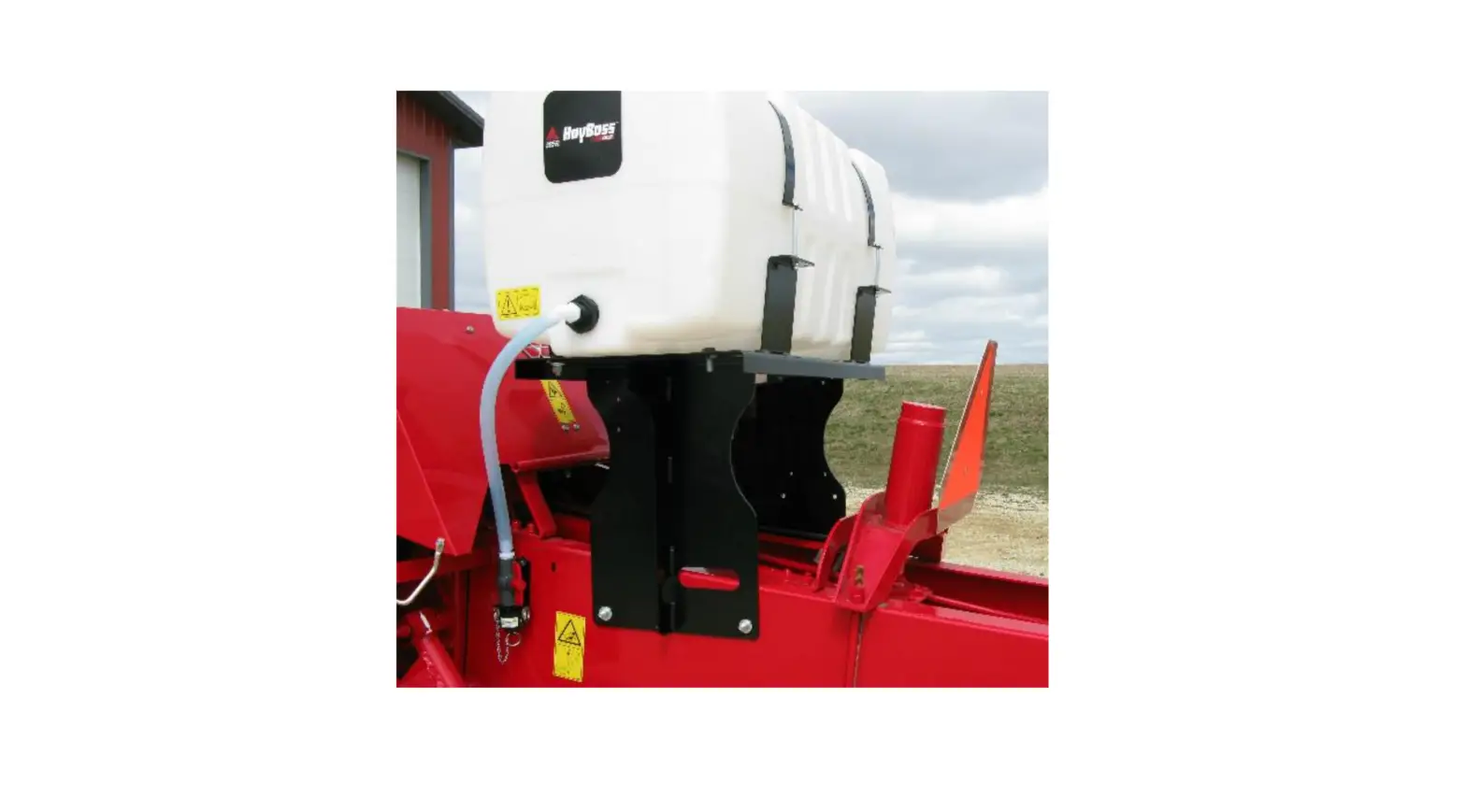
Model 344
Tank legs will be mounted to the back side of baler behind knotters and before the bale tensioner (Figure1).
Using Figure 2 as a reference, mark the two holes on each side of bale chamber that need to be drilled. Line up saddle leg on each side to verify holes before drilling (Figure 3). Drill all four holes to 1/2″ (13mm) in size. Bolt legs to baler with 1/2″ x 1 3/4″ Allen button head bolts, flat washer, Lock washer, and nuts. *Note: bolt head is on inside of bale chamber. Level top of leg before completely tightening bolts, Figure 4.
Bale Thrower – Additional Bracket
When baler is equipped with a bale thrower, bracket (001-4703QC) will need to be used. First secure the kicker so it will not rotate when you remove the front pin on the hydraulic cylinder. Remove pin, install tank leg over mount. Reinstall pin. Use part 001-4703QC which is a spacer that will go between the leg and side of the baler to take up the space the throwers front hydraulic mount adds.
Figure 1
Figure 2
Figure 3
5
Figure 4
Model 344 (continued) Saddle & Tank Mount tank saddle (001-4703X) onto tank legs as shown in figure 5. Bolts are pre-installed on saddle, secure with 1/2″ locks, washers, and nuts.
. Figure 5
Massey 1800 Series Side Mount Tank Mounting Instruction 1. Lay tank and frame assembly on ground next to bale chute on right side of baler. 2. Locate “U” bolts (001-4703QUB) and install them around center hitch tube of baler. Attach to legs of tank frame. Do not fully tighten down nuts. Note: Tube is not parallel to the ground so you will need to offset “U” bolts in frame (001-4703QS). 3. Rotate tank assembly up and check to see if saddle is parallel to ground. If not adjust holes “U” bolts are installed into. 4. Install rear mount (001-4703QU) just in front of “U” bracket on bottom of the bale chamber. You will need to drill 9/16″ holes 13 ½” from rear of bale chute. Secure to baler with two ½” x 1 ¾” BHSC bolts Locks and nuts. 5. Slide tank and saddle frame on pipe to match up with rear mount (001-4703QU) Install two ½” x 1 ¼” bolts, flat washers, lock washers and nuts. 6. Place second mount (001-4703QU) on front leg of tank saddle and mount to baler the same way as rear mount. 7. Check frame again so it is parallel to ground. Tighten down all bolts fully. 8. Attach pump. a. For Electronic and manual systems mount pump on rear of saddle. b. For Automatic systems mount pump plate to outside edge.
6
Model 344 (continued)
344 Pump Manifold
Locate parts bag 8. Using two 3/8″ x 1/4″ bolts, locks, washers, and nuts. Mount the U-shaped pump plate mount 001-4647 (right) onto the tank saddle in the mounting holes located between the strap brackets on back of saddle (figure 7).
Connect the pump plate mounting bracket (001-4648X), shown in figure 8, using two 3/8″ x 1 1/4″ bolts, nuts, locks, and flat washers to the mounting bracket. Install the pump plate as shown completed in figure 9.
Figure 7
Figure 8
Figure 9
Massey 1800 Series Side Mount Tank Pump Manifold will mount directly to the tank saddle as shown below.
Connect the pump plate mounting bracket (001-4648X), using two 3/8″ x 1 1/4″ bolts, nuts, locks, and flat washers to the tank saddle (001-4703S). Install the pump plate as shown completed in figure 10.
7
Model 345
Figure 10
Mount the unit on the diagonal frame behind the twine box, as pictured using the base clamp (001-4406) and u-bolts (001-4406A). The tank and pump assembly is shown below (figure 1). Bolt one end to the top stub pipe on the tank saddle and the other end to a secure location on the baler (figure2). NOTE: REACH RODS MAY HAVE TO BE BENT ON THE TAB TO ALIGN PROPERLY.
Figure 1 Mounting Control Box
Figure 2
Locate the Three Hundred Series control box (006-3671SS) and two vinyl clips (008-9013) from parts bag 17. Mount the control box to the stub pipe by using two 1/4″ x 1″ bolts, 1/4″ flat washers, and 1/4″ Nylock nuts, threaded through the mounting holes on control box (Figure 3). The control box will mount on the stub pipe as shown in Figure 4.
Figure 3
Figure 4
8
Model 350
Locate parts bag 7. Attach legs part (001-4703B) to the tank saddle with 3/8″ x 1″ bolts, flat and lock washers. The legs will attach on top of the bale chamber in front of the hydraulic compression area shown in Figures 1 & 2. You will need to drill four 1/2″ (13 mm) holes on top of the chamber to mount the tank and frame. Clamp legs on top of the bale chamber, mark the holes and drill. The 1/2″ x 1-3/4″ allen head carriage bolts will be inserted through the bale chamber along with flat washers so that the carriage head will be inside of the chamber. Secure the allen head carriage bolts with 1/2″ nuts, flat and lock washers. Mount support bracket (001-4424C) at these locations. Two tie models only (Figure 3).
Figure 1 350 Pump Manifold Installation
Figure 2
Figure 3
Figure 4
Figure 5
1. Locate parts bag 8. 2. Locate the two mounting holes as shown in Figure 4. 3. Connect the pump plate mounting bracket and pump assembly (001-4646X), shown in Figure 5 4. Using two 3/8″ x 1 1/4″ bolts, nuts, locks, and flat washers to the saddle.
9
Model 351
Locate parts bag 12. Mount the two long strap bases (001-4703CD) to the bottom side of the saddle (0014703C) front edge. Note: This is the side that has a 2″ (5 cm) diameter hole in one of the sides. Use four 3/8″ x 1-1/4″ bolts, washers, locks, and nuts to secure. Mount the two short bases (001-4703CC) to the bottom side of the saddle’s back edge. Use 3/8″ x 1-1/4″ bolts on the outside holes. Leave the inside holes open for the installation of the pump plate mount.
Install the “U” shaped pump plate mount (001-4647) to the top and back edge of the saddle. Secure with two 3/8″ x 1-1/2″ bolts on the outside that also go through the short mounting bases as listed above. Place one 3/8″ x 1-1/4″ bolt in the middle. Secure with washers, locks and nuts.
Install the tank fitting into the bottom of the tank (003-EL3412) and mount the tank on top of the saddle and between the strap bases. Locate the two straps (001-4402). Position the straps over the top of the tank and secure with four 5/16″ x 4-1/2″ bolts and eight nuts. All of the strap bolts need to have double nuts.
Connect the pump plate mounting bracket (001-4648X) using two 3/8″ x 1″ bolts, nuts, locks, and flat washers to the U shaped bracket (001-4647).
001-4647 001-4648X
001-4402 005-9203SQ Front of Baler
001-4703CC
Bolt to bottom side of saddle
001-4703CD 001-4703C
10
Model 351 (continued) Mount the tank as shown below on the right side of the baler. The side tank fitting will be facing the right side of the baler. The pump plate assembly will be at the back of the baler. Place the tank on top of the baler and open the front access door (Figure 1). Position the tank so that the front access door can be lifted open and locked in place. Line up the side of the tank saddle closest to the plunger with the bolts on top of the hood. Remove the two bolts, line saddle up with existing holes, and secure with new M8 x 30 bolts, flat washers, and locks. The back access door will be held open with the door strap. Mark and drill two 3/8″ (10mm) holes on the top of the baler for the other open holes in the saddle to attach, secure with two 8mm x 30mm bolts, locks, flats, and nuts. Before drilling, verify that the hole placement will not interfere with any baler operation.
Figure 1
11
Installation of Drain Fill Kit (Models 344, 350 & 351)
Model 344
Using parts bag 1, locate the pre-drilled hole at the front of the bale chamber (Figure 1). Secure valve assembly to baler using 5/16″ x 3/4″ carriage bolts (Figure 2). Thread 3/4″ (19mm) elbow fitting into tank, cut hose to correct length and connect to valve assembly. Secure with hose clamps on both ends (Figure 3).
Figure 1 Model 350
Figure 2
Figure 3
Locate parts bag 1. Install the straight fitting (003-A3434) or elbow fitting (003-EL3434) into the side fitting in
the tank (Figure B). Drill two 5/16″ (8mm) holes using the valve holder (001-6702H) as a template on the right side of the baler above the tire. Mount the valve holder with two 5/16″ x 1″ self-tapping bolts and flange nuts. Attach the 3/4″ (19mm) cam coupler to the 3/4″ (19mm) ball valve through the valve holder. Insert the straight fitting (003-A3434) into the ball valve. Cut the 3/4″ (19mm) hose to length secure on both sides using hose clamps. Install supplied safety decals (DCL-8001 & DCL-8005) next to the ball valve assembly.
Model 351
Locate parts bag 1. Thread 3/4″ (19mm) elbow fitting into end of tank (003-EL3434). Run 3/4″ (19mm) hose from the elbow down the frame to the bottom of the baler. Drill 1/4″ (7mm) holes to accept the valve holder bracket and use 5/16″ x1″ self-tapping screws and flange nuts. Connect valve assembly to other end of hose. Place hose clamps on both ends. Secure hose to frame using zip ties. Install supplied safety decals (DCL-8001 & DCL-8005) next to the ball valve assembly.
12
Placement of Spray Nozzle Assembly Install Kit 4409C
1. Mount the left-hand nozzle strap (it has an elbow fitting and
a silver tip) so that it is approximately 80% across the width of the pick-up head. Example: if the head is 60″ wide, locate the nozzle 48″ from the right side of the head (60″x 80″).
2. Mount the right-hand nozzle strap (it has a tee fitting and a silver tip) in the center of the pickup head.
3. Bend the nozzle bar in so that the tip is pointed in toward the bottom of the gathering chamber and about 16″ above the sheet metal base of the chamber. Twist the nozzle so the tip is tilted 45 degrees from horizontal.
4. One 1/4″ lines will need to be run from the hose manifold to the nozzle straps.
Install Kit 4410C
Install Hoses before installation of shield. Bolt the shield assembly (Figure 1) up under the baler’s hood. Remove 3 bolts shown in Figure B (labeled A, B, C) on the baler and replace with hardware in kit to fasten
lip securely in place. One 1/2″ line will need to be run from the hose manifold to the spray shield.
A
A B
C
B
Figure 1
C
Figure 2
Install Kit 4412C
Align the shield, with brackets attached, to the front sheet metal 10″-14″ (25 36 cm) from the edge of the knife in the baler chamber. The spray pattern should be aimed towards the middle of the baler chamber. Verify the mounting location will not interfere with any baler functions. Mark and drill 4 holes with a 10 mm drill bit. Install the shield using 3/8″ x 1-1/4″ bolts, flat and lock washers, and nuts.
13
Install Kit 4415C
Locate the hay guard directly above the bale chamber. This install can be done with the hay guard in the baler, but it is recommended removing it for ease of installation. Consult your dealer for guidance.
Installation of Spray Shield
1. Mark a point 9-1/4″ (24cm) from the knife on the hay guard and draw a squared line across width. 2. Remove hay guard from baler if possible. Mark the top and bottom of the hay guard for the correct re-
installation. 3. Back out plastic drill guides from the gray spray shield until they are flush with the bottom of the spray
shield. Line up the spray shield on the hay guard with the KNIFE sticker against the line just marked. 4. Center and clamp the spray shield firmly in place. 5. Using a 1/2″ (13mm) drill bit, mark the location of the two 1/2″ (13mm) holes to create a center mark. DO
NOT DRILL THROUGH STEEL. 6. Remove spray shield. On the holes just marked, use a 1/4″ (7mm) drill bit and drill through both pieces of
steel as square as possible. 7. Insert two 1/4″ x 2″ button head cap screws through holes in the bottom of the hay guard. The head of the
screw will need to be down (in the chamber). Secure with nylon lock nut on top side. 8. Replace spray shield and secure with the hold-down knobs. 9. Drill out the two holes with drill guides installed with a 1/4″ (7mm) drill bit. Drill through both pieces of steel. 10. Remove the spray shield and use a 1-1/2″ (38mm) hole saw, drill the two holes through the TOP STEEL
ONLY. 11. Drill out the bottom holes with a 9/16″ (14mm) bit. Be careful not to oblong the holes. De-burr any metal
filings left around the three holes on both sides of the hay guard. Use touch-up paint on bare surfaces to preserve the metal and the baler. 12. Remove plastic drill guides from the shield and thread the elbow completely into the spray shield. 13. Thread both elbows into the shield. Install the high output tips (004-1104-SS) onto the elbows by securing with nozzle caps (003-BC12). 14. Back the threaded fittings out as far as possible. Place the shield on the hay guard and secure by pressing down. Secure the spray shield with the hold-down knobs. 15. Thread both elbows down until they touch the bottom metal and align as needed for routing the hoses. NOTE: Tips should protrude slightly out of the bottom of the hay guard with no space between the tip and the hole. 16. Re-install hay guard onto the baler. 17. Align nozzle at 45 degree angle inside the chamber.
Installation of Hose and Support Bracket
1. If the hay guard was removed for shield installation reinstall at this time. 2. Mark a point 6″ (15cm) from the first rotating tine on the center of the hay guard. Center punch this mark
and drill a 1/4″ (7mm) hole through both the top and bottom of the hay guard. 3. Bolt the bottom bracket (001-4425B) using 1/4″ x 2″ button head cap screw. Secure with a 1/4″ flange nut.
The head will need to be down (in the chamber). 4. Loosely install the remaining bracket (001-4425B) to the bottom bracket attaching in the middle. Level the
two pieces and extend the top bracket until it reaches the top of the baler. Secure with a 1/4″ flange bolt and nut. 5. Mark and drill the top hole with a 1/4″ (7mm) bit. Secure with a 1/4″ (7mm) flange bolt and nut. 6. Route the hoses from the pumps down the cross member of the tank is mounted on towards the right side tire. The hose will go up the right side of the baler towards to the top and center of the baler towards the hole that will be made in the next step. 7. Cut a 1-1/2″ hole in the top of the baler for the hose to route through. Install the grommet once the hole is complete. 8. Install the hoses from the elbows on the shield, under the hay tine, to the bracket, and out the 1-1/2″ hole in the hood of the baler. Cut hose to 10″ outside the hole.
14
Install Kit 4415C (continued)
9. Secure hoses on the end of spray shield with two jiffy clips (008-9014) and 1/4″ x 1/2″ round head screw. 10. Secure the hose to the bracket with two jiffy clips (008-9014) and 1/4″ flange bolts and nuts. Keep the hose
in the center of the bracket. 11. Attach the Y fitting (003-Y1414) to the hoses leaving the hole in the hood of the baler. Cut 6″ to go between
single leg of Y fitting and pulsing solenoid. 12. Install the 1/2″ hose from the pump to the straight 1/4″ x 1/2″ fitting (003-A1412) connected to solenoid.
1-1/2″ hole
Y Fitting (003-Y1414)
Solenoid (002-2203F)
Hay Guard
Spray Shield
Location of first rotating tine
Brackets 001-4425B
View from behind the twine box with the inspection door open.
15
Install Kit 4416C, 4417C & 4485C
On baler tongue above center of the baler (Figure 1), install spray shield holders (001-4424B) on both sides of tongue using pre-drilled holes (Figure 2). Securing each with one 3/8″ bolt. Do not tighten bolts. Place the spray shield (001-4424A2) on the shield holders using two 3/8″ bolts, washers, lock and nuts. Spray shield should spray toward back of pickup, between augers, in area before crop enters baler (Figure 3). When angle of tips is correct, tighten shield holder bolts. Route hose to hose manifold.
Figure 1
Figure 2
Figure 3
16
Install Kit 4502C The shield for your baler will mount in the throat of the baler as shown above. Remove nut and bolt on both sides of baler, shown below. Install shield holders (001-4703I) with 1/2 x 2″ bolts, nuts, locks and flat washers. Do not tighten these bolts until the shield is properly aimed. Aim the shield at bottom of the pickup head at the point where stuffer fingers connect with hay (between the two augers) and make sure the bushing is not removed. Once the shield is in place the nuts may be tightened down.
Install Kit 4506C The shield for your baler will mount on top of the sheet metal directly above the pickup head shown in the picture below. Mount shield holder (001-4703H) on top of metal 6″ (15cm) from the front of the baler and 10″ (25cm) from the side of the baler. Attach this holder with 1/4 x 1 1/4″ self-tapping bolts. Place shield of top of holder and rotate the shield to a 45-degree angle. Mark the location of the next holder’s position and install. Four holes will need to be drilled below the tips using a 3/4″ (19mm) hole saw or bit.
001-4703H 10″ (25cm) 6″ from front (15cm)
17
Install Kit 4507C The shield for your baler will mount on the wrap guard as shown in the picture above. Remove the two outside bolts on each side of the wrapper guard. Place bracket 001-4703G so pins are facing up and bolt through with 3/8 x 1-1/2″ into bracket 001-4703G, through wrap guard, and into threaded holes on baler frame that the bolts were removed from.
001-4703G
Outside bolts
Installation of Plumbing
Model 344, 345 & 350 A. Intake
Locate parts bag 16. Use the 003-EL3412 on the bottom of the tank to route 1/2″ line (002-9001) to the 003-A1212 or 003-EL1212 fitting used on the ball valve attached to the pump plate. Attach hose clamps (003-9003) on both of the fittings. B. Discharge Route the 1/2″ hose from the pump output toward the front of the baler and connect to the solenoid assembly (SOL-3SP-B). Secure the solenoid assembly and hose along baler, positioning the solenoid as close to the spray tips as possible. Connect the 1/4″ hose to the outgoing side of the solenoid to tip assembly.
Model 351 A. Intake
Locate parts bag 16. Use the 003-EL3412 on the bottom of the tank to route 1/2″ line (002-9001) to the 003A1212 or 003-EL1212 fitting used on the ball valve attached to the pump plate. Attach hose clamps (0039003) on both of the fittings. B. Discharge Route the 1/2″ hose from the pump output toward the front of the baler and connect to the solenoid assembly (SOL-3SP-A). Secure the solenoid assembly and hose along baler, positioning the solenoid as close to the spray tips as possible. Connect the 1/4″ hose to the outgoing side of the solenoid to tip assembly.
18
Installation of End of Bale Sensor
Mount the 006-7400 sensor to the mounting bracket 001-4648SI for AGCO as shown below (Figure 1). Case IH, New Holland, & John Deere and other balers will use bracket 001-4648SS. Mount the assembly on the right side of the baler chamber. The face of the sensor needs to be parallel to the arm attached to the needles (Figure 2). Mark and drill two 3/8″ (10mm) holes. Install the sensor using two 5/16″ x 1″allen head bolts, locks, and nuts. The end of the sensor needs to be no greater than 1/4″ (7mm) away from the needle arm. Tighten nuts on sensor after adjustment.
001-4848SS or
001-4648SI
006-7400
Figure 2
Figure 1 .
Installation of Star Wheels
Model 344, 345, 350 & 351 Two- Tie only)
The pair of star wheels will need to mount on the bottom side as close to the front of the bale chute as possible and at least 3/8″ (10mm) away from any metal. They will need to maintain a safe distance away from the twine.
The star wheels will require two holes to be drilled per block, when drilling make sure to keep the wheel square to the bale chamber. Any angle will cause stress on the wheel and will eventually cause the wheel to work itself out of the block. Some balers may require a notch cut on the bottom of the bale chamber to mount the star wheels as close to the front of the chamber as possible.
Use the supplied bolts and place the carriage head inside of the bale chamber followed by lock and nut. Next attach the star wheels to the bolts followed by flat washer, lock washer and nut.
First, remove the cover from the star wheel block and use a 1/4″ (7mm) nut driver to remove the nut from the electronic swivel. Next, run the star wheel sensor wire through the black grommet and place the eye terminal on the star wheel sensor. Tighten the eye loop with the nut on the sensor and put the star wheel cover back on the base. Next, tighten the grommet to form a tight seal around the wire. Once the star wheel connection is complete, run the harness along the baler frame to the Three Hundred Series (THS) controller.
Model 351
Model 344, 345 & 350
19
Installation of iPad Integration Control Locate a safe location in the cab of the tractor to place the iPad Integration Control (030-6672C). Recommended location is securely fastened out of the operator’s way in a location that is close enough to reach with the iPad cord.
Connect the Power / Communication harness (006-6650TM(E)) to the bottom of the receiver.
To operate the applicator, plug the iPad cord into the communication port indicated by:
iPad Integration Control Light Signals Green Slow Blink Power supplied to the applicator system and the unit is going through its startup process. This will take approximately 25-35 seconds.
Green Double Blink Indicating the iPad module recognizes the iPad but the app is not open or connected. Green Solid Light Module is connected to the app and is ready to operate. *Recommended to use the USB cable included with the applicator kit (006-6672USBC)
Bluetooth Receiver Lights
Pre-2020 applcaitors equipped with Bluetooth receivers (030-6672B) are now equipped with lights to indicate both power and Hay App connection on the Apple iPad. Clean light regularly
Blinking Lights System is waiting for the processor to connect, which could take up to 35 seconds.
Red Light The Bluetooth receiver has power Green Light The Bluetooth receiver is connected to the Hay App.
300 Series Applicators with serial number before THS07000 will require the THS to be sent to Harvest Tec for a required update in order to use the iPad Integration Module (030-6670C).
Hay App version must be at least 2.7.1 (or higher) to operate with the iPad Integration Module (030-6672C)
*Made for Apple iPad badge Use of the Made for Apple iPad badge means that an accessory has been designed to connect specifically to the Apple product(s) identified in the badge and has been certified by the developer to meet Apple performance standards. Apple is not responsible for the operation of this device or its compliance with safety and regulatory standards.
Please note that the use of this accessory with an Apple product may affect wireless performance.
20
Wiring Diagram 344, 345, 350, 351
1. Connect the power harness (006-3650T) to the tractor battery (12 volt) using the red wire with fuse to the positive side and the black wire to the negative. A. The power harness must be connected to the battery! The unit will draw more amps than convenience outlets can handle. Any modifications of the power harness will void systems warranty. CONTACT HARVEST TEC BEFORE MODIFICATIONS. B. This unit will not function on positive ground tractors. C. If the unit loses power while operating it will not keep track of accumulated pounds of product used.
2. The power harness on the tractor (006-3650T) will run from the tractor battery to the hitch. The power harness on the baler (006-3650B1) will connect to the tractor power harness (006-3650T) at the hitch.
3. Connect the keyed power wire (006-5650K) to a keyed power source on the tractor. The keyed power wire must connect to a keyed source or the unit will not power up correctly.
4. Attached the iPad Integration Control (030-6672C) to the tractor power harness (006-3650T). 5. Attach the End of Bale (EOB) connection on the controller to the End of Baler Sensor (006-7400). 6. Attach the Solenoid (V1) (Delphi connector) connection on the controller to the wire from the solenoid
(002-2203F). Note: If solenoid is connected to V2-DSM (not used) connection, solenoid will not work. 7. Attach the Flowmeter (FLOW) connection on the controller to the flowmeter (006-4729A).
A. Attach the spade connectors on the FLOW harness to the Pump (007-4120DE).
System wiring diagram
iPad Integration Control 030-6672C
300 Control Box 006-3671SS
Orange Wires to Keyed Power 006-5650K
Power Harness on Tractor Power/ Harness on Baler
006-3650T
006-3650B1
Hay Indicator Harness 006-7502H
Moisture Content (MC%)
Harness EOB V1 EOR FLOW
V2-DSM Pump
Color Brown White (Delphi Connector) Yellow White White (Delphi Connector) Orange
Moisture Harness 006-4640D2
or 006-4640K2
21
End of Bale Sensor 006-7400
Solenoid 002-2203F
Hay Indicators
Flow Meter 006-4729A
Pump 007-4120DE
Moisture Disc 006-4642 (x2)
Pin Outs
Power Harness 006-3650T at Tractor Hitch
Pin 1 Red
+12V Power to BLE
Pin 2 Red
+12V Power to THS
Pin 3 Orange
Keyed Power
Pin 4 Not Used
Pin 5 Green
HT Can Low
Pin 6 Yellow
HT Can Hi
Pin 7 Not Used
Pin 8 Black
Ground from BLE
Pin 9 Black
Ground from THS
Pin 10 Not Used
Power Harness 006-3650B1 at Baler Hitch
Pin 1 Red
+12V Power to BLE
Pin 2 Red
+12V Power to THS
Pin 3 Orange
Keyed Power
Pin 4 Not Used
Pin 5 Green
HT Can Low
Pin 6 Yellow
HT Can Hi
Pin 7 Not Used
Pin 8 Black
Ground from BLE
Pin 9 Black
Ground from THS
Pin 10 Not Used
iPad Integration Control / BLE on Harness 006-3650T
Pin 1 Red
+12V Power for BLE
Pin 2 Black
Ground for BLE
Pin 3 Yellow
HT Can Low
Pin 4 Not Used
Pin 5 Green
HT Can Hi
Pin 6 Not Used
Pin 7 Not Used
End of Bale Sensor at 300 Controller Harness
Pin 1 Brown
Sensor Power
Pin 2 Blue
Sensor Ground
Pin 3 N/A
Pin 4 Black
Signal from Sensor
Flow Meter at 300 Controller Harness
Pin 1 White
+5-12V Power
Pin 2 Brown
Ground
Pin 3 Green
Signal
Pin 4 Not Used
22
Pin Outs (continued)
End of Row Sensor at 300 Controller Harness
Pin 1 Red/White
+12V Power
Pin 2 Black/White Ground
Pin 3 Yellow
Signal
Pin 4 N/A
Moisture Sensor connection at 300 Controller Harness
Pin 1 Not Used
Pin 2 Not Used
Pin 3 Not Used
Pin 4 Not Used
Pin 5 Not Used
Pin 6 Not Used
Pin 7 Not Used
Pin 8 Blue
Signal for Sensor 1
Pin 9 Blue
Signal for Sensor 2
Pump connection at 300 Controller Harness Pin 1 Red Power to Pump Pin 2 Black Ground to Pump
Solenoid Connection at 300 Controller Harness Pin A Black Solenoid Pause Pin B White Solenoid Ground
V2-DSM Connection at 300 Controller Harness Pin A Black Solenoid Pause Pin B White Solenoid Ground
23
Pin 1 Pin 2
Pin A
Pin B
Pin A
Pin B
Parts Breakdown Model 344 Base Kit- Top Mount
2
1
7 3
5
6
4
Ref# Description Part #
Qty
Ref# Description
Part #
Qty
1 Tank
005-9203SQ 1
5 Tank fitting
005-9100
1
2 Tank lid
005-9022H
1
6 Strap Base
001-4703CC 4
3 Tank straps 001-4402
2
7 Pump Plate Mount 001-4647
1
4 Tank Saddle 001-4703X
1
Tank Saddle Kit (1-5) 030-0432-TK
4647 Mount Kit (6) PMP-4647MT
Model 3444417C Base Kit-Side Mount
2
1
3
6
4
Ref# Description Part #
Qty
1 Tank
005-9203SQ 1
2 Tank lid
005-9022H
1
3 Tank straps 001-4402
2
Ref# 4 5 6
Description Tank Saddle Tank fitting Strap Base
Part #
Qty
001-4703S
1
005-9100
1
001-4703CD 4
Tank Saddle Kit (1-5) 030-0432-TK 4647 Mount Kit (6) PMP-4647MT
24
Model 345 Base Kit
1
Ref Description
Part #
Qty
2
4
1 Tank Cap
005-9022C 1
2 Tank Cap Gasket 005-9022CG 1
3
3 Tank Strap 4 Stub Pipe
001-4402
2
001-4403
1
5 Tank
005-9022
1
6 Saddle
001-4401
1
5
7 Tank Fitting
005-9100
1
*25-Gal Tank Includes Bottom Fitting Only Tank Saddle Kit 030-0441-TK
6
7
Model 350 Base Kit
4 5 1
2
6 3
Ref# Description Part # Qty
1 Tank
005-9203 1
2 Straps
001-4402 2
3 Tank Fitting 005-9100 1
Ref# 4 5 6
Description Tank Cap Tank Gasket Saddle
Part #
Qty
002-9022C
1
002-9022CG 1
001-4703
1
*55-Gal Tank Includes Side Tank Fitting Only Complete Saddle Kit 030-0448-TK
25
Model 351 Base Kit
8 3 1
6 4
7 5
2
Ref# Description
Part #
Qty
1 Tank
005-9203SQ
1
2 Tank Saddle
001-4703C
1
3 Tank Straps
001-4402
2
4 Short Strap Base 001-4703CC
2
5 Tank fitting
005-9100
2
Ref# 6 7 8 NP
Description Mounting Bracket Door Latch Tank Lid Long Strap Base
Part #
Qty
001-4647
1
001-4703CL 1
005-9022H
1
001-4703CD 2
*Tank Includes Cap, Bottom & Side Tank Fitting
Complete Saddle Kit (1-5,7-NP) 030-0440-TK
4647 Mount Kit (6)
PMP-4647MT
26
Parts Breakdown for Pump Assembly
001-4648X
Part#
Description
Qty
003-EL3812
3/8″MPT X 1/2″HB Elbow 1
007-4120DE 300 Series Pump
1
003-M3838
3/8″ x 3/8″ Union
1
003-SE38
3/8″ Street Elbow
1
002-4566F
3/8″ Check Valve
1
003-RB3814PB RB 3/8″ x 1/4″ Reducer
1
006-4729A
Flow Meter Block Style 1
003-RB1214PB RB 1/2″ x 1/4″ Reducer
1
003-M1212F 1/2″ Coupler
1
Part# 003-M1212 002-4315-100 003-SE12 002-2212 003-EL1212 001-4648XL 001-4648X 003-A1212 003-A3812
Description
Qty
1/2″ Union
2
1/2″ Line Strainer-100 Mesh 1
1/2″ Street Elbow
1
1/2″ Ball Valve
1
1/2″MPT x 1/2″HB
1
300 Pump Support
1
Pump Plate Mount
1
Not Pictured
Not Pictured
Pump Assembly PMP-3636P (001-4648X Not Included)
Completed Assembly
*Note: Due to alternative baler designs, elbow 003-EL3812 can be replaced by straight fitting 003-A3812. As well as elbow 003-EL1212 can be replaced by straight fitting 003-A1212. Both straight fittings are included.
27
1 23 10
Star Wheel Sensors
5 4
9 8
Ref Description
Part#
Qty
6
1 Washer (per side) 006-4642K
2
2 Dust Seal (per side) w/006-4642K 1
3 Snap Ring (per side) w/006-4642K 2
4 Swivel
006-4642A
2
5 Star Wheel
030-4641E
2
6 Insert
w/ Ref # 5
2
7 Wiring grommet
008-0821A
2
7
8 Star wheel block
006-4641D 2
9 Plug Fitting
003-F38
2
10 Block Cover
006-4641B
2
1-10 Star wheel assembly 030-4642
2
Hoses
Moisture Harness
11
12
Ref Description
Part #
Qty
11
1/2″ Hose (Tank to Solenoid)
002-9001
15ft
12
1/4″ Hose (Solenoid to Tips)
002-9016
6ft
Ref Description NP Moisture Harness
(344,345,350 Kits) NP Moisture Harness
(351 Kit)
Part #
Qty
006-4640D2 1
006-4640K2 1
28
Control Box and Wiring Harnesses
2
4
5
1 or 7
3 6
Ref Description
Part#
Qty
1
Power lead baler 20′ (344, 345, 350 Kits)
006-3650B1
1
2 Power lead tractor 006-3650T
1
3 Key Switch Wire
006-5650K 1
4 iPad Integration
030-6672C 1
Control
End of Bale Sensor Kit A
Ref Description
Part#
Qty
5 300 Series Controller
006-3671SS
1
6 Dust Plugs
006-5651Plugs
1
7 Power lead baler 30′ (451) 006-3650B2
1
NP USB Cable
006-6672USBC
Complete Assembly (1-6) 030-362CPA Complete Assembly (2-7) 030-362CPB
End of Bale Sensor Kit B
1
2
3
Ref Description
Part #
Qty
1 End of Bale Sensor 006-7400
1
2 EOB Extension
006-7400EXT 1
3 End of Bale Bracket 001-4648SS 1
Complete Assembly EOB-SS-A
4
5
6
Ref Description
Part #
Qty
4 End of Bale Sensor 006-7400
1
5 EOB Extension
006-7400EXT 1
6 End of Bale Bracket 001-4648SI
1
Complete Assembly EOB-SS-B
29
300 Solenoid Packages
1 2
3
4 5
6
7 8
10 9
Solenoid Package A
(Applicator Kit: 351)
Ref Description
Part #
Qty
1 Solenoid Harness (5′) 006-3650-S1 1
2 #6 Hose Clamp
003-9003
1
3 1/4″ x 1/2″ Straight Fittng 003-A1412
1
4 1/4″ Female Connector 004-1207G
1
5 Rubber Washer
004-1207W 2
Ref Description
Part #
Qty
6 1/4″ Female Disconnect 004-1207H 2
7 Solenoid
002-2203F 1
8 Solenoid Valve Body
004-1207VF 1
9 1/4″ x 1/4″ Straight Fitting 003-A1414 1
10 Mini Hose Clamp
003-9002
1
Complete Assembly
SOL-3SP-A
Solenoid Package B
(Applicator Kits: 344, 345, 350)
Ref Description
Part #
Qty
1 Solenoid Harness (10′) 006-3650-S2 1
2 #6 Hose Clamp
003-9003
1
3 1/4″ x 1/2″ Straight Fittng 003-A1412
1
4 1/4″ Female Connector 004-1207G
1
5 Rubber Washer
004-1207W 2
Ref Description
Part #
Qty
6 1/4″ Female Disconnect 004-1207H 2
7 Solenoid
002-2203F 1
8 Solenoid Valve Body
004-1207VF 1
9 1/4″ x 1/4″ Straight Fitting 003-A1414 1
10 Mini Hose Clamp
003-9002
1
Complete Assembly
SOL-3SP-B
30
Parts Bag Packages
PBA-1
PBP-16
1
5
10
12
8
6 2
9
3 7
4
Ref Description
Part #
Qty
1 3/4″ Ball Valve
002-2200
1
2 Valve Holder
001-6702H
1
3 Female Coupler
002-2204A
1
4 Male Shut-Off Plug
002-2205G
1
5 3/4″ x 3/4″ Elbow
003-EL3434 1
6 #10 Hose Clamp
003-9004
2
7 3/4″ x 3/4″ Straight Fitting 003-A3434
1
8 Valve Decal
DCL-8004
1
9 Chemical Hazard Decal DCL-8001
1
Complete Drain Fill Kit
030-0493DFK
PBP-12
14
11
13
Ref Description 10 3/4″ x 1/2″ Elbow 11 3/4″ Jiffy Clip 12 #6 Hose Clamp 13 Small Jiffy Clip
Part #
Qty
003-EL3412 1
008-9010
3
003-9003
1
008-9009
3
PBP-17
15
Ref Description Part #
Qty
14 Door Latch
001-4703CL 1
Ref Description 15 Vinyl Clamp
Part #
Qty
008-9013 1
31
Optional iPad Mini Mounting Kit (030-2014MK)
2 1
3
4
5
7
6
8
Ref Description 1 Suction cup mount 2 Ram mount 3 iPad Mini® spring load cradle (Mini 2) 4 16 gauge power wire 5 Female spade connector 6 Eye loop connector 7 iPad Mini® Charger 12V 8 iPad Mini 4 case NP 4 amp fuse
Part #
Qty
001-2012SCM
1
001-2012H
1
001-2012SLC
1
006-4723P
1
Hardware
2
Hardware
2
001-2012P
1
001-2012C4
1
Hardware
1
Mounting Kit Assembly
030-2014MK (Includes All Parts)
Installation Instructions
1. Identify 12V power source for wires to connect. a. Eye loops included if wiring directly to the battery is desired. b. Test for key power source if preferred to have power to the USB shut off with the key.
2. Once power source is identified, cut wires to desired length. 3. Crimp the two supplied quick connectors onto each the white and black wire. 4. Remove the round locking plastic nut from USB plug before connecting the wires. Black (+) White (-). 5. The wires will then be hooked to the designated terminals on the bottom of the USB plug 6. Drill a 1 1/8″ hole in the preferred mounting location. Be sure to clean any sharp edges after drilling. 7. Feed the wires through the mounting hole. 8. If using the round plastic nut to secure plug-in place, slide the nut back over the wiring before
connecting the wires to powered source. 9. Connect the wires to the identified power source if easier to do so before tightening the plug into place. 10. Tighten plug using either the round plastic nut or mounting plate and two screws, both options supplied. 11. Once connected, hook a USB charging cord into the plug and connect a mobile device/tablet to ensure
the plug is operating as you wish (key power working properly if necessary).
NOTE: This plug is not designed to charge two iPads. System damage could occur if this is attempted. System will charge a mobile phone and iPad simultaneously without problem.
*iPad mini is a trademark of Apple Inc., registered in the U.S. and other countries.
32
Optional iPad Display Kit (030-4670DK)
9 2 1
3
7
4
5
6
8
Ref Description
Part #
Qty
1 Suction cup mount
001-2012SCM 1
2 Ram mount
001-2012H
1
3
iPad Mini spring load cradle (Mini 4)
001-2012SLC 1
4 16 gauge power wire
006-4723P
1
5 Female spade connector Hardware
2
6 Eye loop connector
Hardware
2
Ref Description
Part #
Qty
7 iPad Mini Charger 12V 001-2012P 1
8 iPad Mini 4 case
001-2012C4 1
9 iPad Mini 4
006-4670IP 1
NP 4 amp fuse
Hardware
1
Mounting Kit Assembly
030-4670DK (Includes All Parts)
Installation Instructions
1. Identify 12V power source for wires to connect. 2. Eye loops included if wiring directly to the battery is desired. 3. Test for key power source if preferred to have power to the USB shut off with the key. 4. Once power source is identified, cut wires to desired length. 5. Crimp the two supplied quick connectors onto the white and black wire. 6. Remove the round locking plastic nut from USB plug before connecting the wires. Black (+) White (-). 7. The wires will then be hooked to the designated terminals on the bottom of the USB plug 8. Drill a 1 1/8″ hole in the preferred mounting location. Be sure to clean any sharp edges after drilling. 9. Feed the wires through the mounting hole. 10. If using the round plastic nut to secure plug in place, slide the nut back over the wiring before connecting
the wires to powered source. 11. Connect the wires to the identified power source if easier to do so before tightening the plug into place. 12. Tighten plug using either the round plastic nut or mounting plate and two screws, both options supplied. 13. Once connected, hook a USB charging cord into the plug and connect a mobile device/tablet to ensure
the plug is operating as you wish (key power working properly if necessary).
NOTE: This plug is not designed to charge two iPads. System damage could occur if this is attempted. System will charge a mobile phone and iPad simultaneously without problem.
*iPad mini is a trademark of Apple Inc., registered in the U.S. and other countries.
33
Model 4409C Installation Kit
2
3 45
1
6
7
8
9
10 12
11
Ref Description
Part #
Qty
1 Nozzle Holder
001-4215
2
2 1/4″ Hose
003-9016
3
3 Mini Hose Clamp
003-9002
3
4 1/4″ x 1/4″ Straight Fitting 003-A1414
3
5 1/4″ Female Street Elbow 003-SE14F
1
6 Tip Grey
004-T6504-PT 2
7 Tip Pink
004-T6501-PT 2
* Tip color subject to change
Ref Description
Part #
Qty
8 1/4″ Tee Sq
003-TT14SQ
1
9 Reach Rod Outside 001-4404
1
10 Reach Rode Inside 001-4405
1
11 1/2″ x 4″ U-Bolt
001-4406A
2
12 Base Bracket
001-4406
1
Shield Only (Ref 1-8) Tank Mount Kit (Ref 9-12)
Complete Assembly
030-4409C-SO TMK-4401 030-4409C
34
Model 4410C Installation Kit
3
4
2 1
9 10
11
5
6
8
7
12
Ref Description
Part #
Qty Ref Description
Part #
Qty
1 1/4″ Hex Plug
003-F14
1 7 Tip Pink
004-T6501-PT
2
2 Shield Manifold Block
001-4435NSB 2 8 Tip Grey
004-T6504-PT
2
3 Nozzle Holder SS Block 001-4426A
1 9 Reach Rod Outside 001-4404
1
4 1/4″ Hose
002-9016
1 10 Reach Rode Inside 001-4405
1
5 1/4″ x 1/4″ Straight Fitting 003-A1414
3 11 Base Bracket
001-4406
1
6 Mini Hose Clamp
003-9002
3 12 1/2″ x 4″ UBolt
001-4406A
2
* Tip color subject to change
Shield Only (Ref 1-8) Tank Mount Kit (Ref 9-12)
Complete Assembly
030-4410C-SO TMK-4401 030-4410C
35
Model 4412C Installation Kit
1
2
3
4
11
5
6
7 8
10
9
12
13 15
14
Ref Description
Part #
1 Left Mounting Bracket
001-4436DL
2 Right Mounting Bracket 001-4436DR
3 1/4″ Hose
002-9016
4 Mini Hose Clamp
003-9002
5 1/4″ x 1/4″ Straight Fitting 003-A1414
6 1/4″ Sq Tee
003-TT14SQ
7 1/4″ Female St Elbow
003-SE14F
8 Tip Holder Spray Shield 001-4810
* Tip color subject to change
Qty Ref Description
1 9 Tip Pink 1 10 Tip Grey 1 11 3/16″ Lynch Pin 3 12 Reach Rod Outside 3 13 Reach Rode Inside 1 14 1/2″ x 4″ UBolt 1 15 Base Bracket
1
Shield Only (Ref 1-11)
Tank Mount Kit (Ref 12-15)
Complete Assembly
Part #
Qty
004-T6501-PT
2
004-T6504-PT
2
008-4576
1
001-4404
1
001-4405
1
001-4406A
2
001-4406
1
030-4412C-SO TMK-4401 030-4412C
36
Model 4415C Installation Kit
1
2 4
3
6
5
12
9
8
10
7
11
13
14 16
15
Ref Description 1 Hose Support 2 1/4″ Hose 3 Y Fitting 4 1/4″ Nozzle Body Elbow 5 Hay Guard Shield 6 SS Manifold Knob 7 477 Jiffy Clips
* Tip color subject to change
Part #
Qty
001-4425B
2
002-9016
3
003-Y1414
1
003-EL3814NB 2
001-4425C
1
008-0925
2
008-9014
5
Ref Description
Part #
Qty
8 Tip Low Output
004-11001-SS 2
9 Tip High Output
004-11004-SS 2
10 1/4″ Drill Guide
003-M3814NB 1
11 Nozzle Cap
003-BC12
2
12 Mini Hose Clamp
003-9002
5
13 Reach Rod Outside 001-4404
1
14 Reach Rode Inside 001-4405
1
15 1/2″ x 4″ UBolt
001-4406A
2
16 Base Bracket
001-4406
1
Shield Only (Ref 1-12) Tank Mount Kit (Ref 13-15)
Complete Assembly
030-4415C-SO TMK-4401 030-4415C
37
Model 4416C Installation Kit
12
3
4
5
6
7
8
10
9
11
12
13
Ref Description
Part #
Qty
1 Spray Shield Holders 001-4424B
2
2 Spray Shield
001-4424A2
1
3 1/4″ Straight Fitting 003-A1414
2
4 1/2″ Otiker Clamp
003-9008
4
5 1/4″ Hose
002-9016
1
6 Manifold Block
001-4435NSB 2
7 Hex Plug
003-F14
2
* Tip color subject to change
Ref Description 8 1/4″ Tee 9 Tip – Pink 10 Tip – Grey 11 Mini Hose Clamps 12 Saddle Legs 13 Kicker Bracket
Part#
Qty
003-T1414
1
004-T6501-PT 2
004-T6504-PT 2
003-9002
1
001-4703Q
2
001-4703QC
1
Shield Only (Ref 1-11) 030-4416C-SO
Tank Mount Kit (Ref 12-13) TMK-4416
Complete Assembly
030-4416C
38
Model 4417C Installation Kit
12
3
4
5
6
7
8
10
9
11
13
14
12
Ref Description
Part #
Qty
1 Spray Shield Holders 001-4424B
2
2 Spray Shield
001-4424A2
1
3 1/4″ Straight Fitting 003-A1414
2
4 1/2″ Otiker Clamp
003-9008
4
5 1/4″ Hose
002-9016
1
6 Manifold Block
001-4435NSB 2
7 Hex Plug
003-F14
2
* Tip color subject to change
Ref Description
Part#
Qty
8 1/4″ Tee
003-T1414
1
9 Tip – Pink
004-T6501-PT 2
10 Tip – Grey
004-T6504-PT 2
11 Mini Hose Clamps 003-9002
1
12 Support Bracket
001-4703QU
1
13 U-Bolt
001-4703QUX 2
14 U-Bolt
001-4703QUB 2
Shield Only (Ref 1-11) 030-4416C-SO
Tank Mount Kit (Ref 12-13)
Complete Assembly
030-4417C
39
Model 4485C Installation Kit
12
3
4
5
6
7
8
10
9
11
12 13
Ref Description 1 Spray Shield Holders 2 Spray Shield 3 1/4″ Straight Fitting 4 1/2″ Otiker Clamp 5 1/4″ Hose 6 Manifold Block 7 Hex Plug
Part #
Qty
001-4424B
2
001-4424A2
1
003-A1414
2
003-9008
4
002-9016
1
001-4435NSB 2
003-F14
2
* Tip color subject to change
Ref Description
Part #
Qty
8 1/4″ Tee
003-T1414
1
9 Tip – Pink
004-T6501-PT
2
10 Tip – Grey
004-T6504-PT
2
11 Mini Hose Clamps 003-9002
1
12 Support Bracket
001-4424C
2
13 55 Gal Long Leg
001-4703B
2
Shield Only (Ref 1-11) 030-4416C-SO
Tank Mount Kit (Ref 12-13) TMK-4485
Complete Assembly
030-4485C
40
Model 4502C Installation Kit
6
1 23 4
5
7
9 11
12
8 10
Ref Description
Part #
Qty
1 3/16″ Lynch Pin
008-4576
2
2 Mini Hose Clamp
003-9002
3
3 1/4″ x 1/4″ Elbow
003-EL1414
1
4 1/4″ Tee Sq
003-TT14SQ 1
5 1/4″ x 1/4″ Straight fitting 003-A1414
2
6 1/4″ Hose
002-9016
1
7 1/4″ Female Street Elbow 003-SE14F
1
* Tip color subject to change
Ref Description
Part #
Qty
8 Shield Holder
001-4703I
2
9 Spray Shield
001-4703G
1
10 Tip Pink
004-T6501-PT
2
11 Tip Grey
004-T6504-PT
2
12 55 Gal Long Leg 001-4703B
2
Shield Only (Ref 1-11) 030-4502C-SO
Tank Mount Kit (Ref 12) TMK-4703B
Complete Assembly
030-4502C
41
Model 4506C Installation Kit
6
1 23 4
5
7
9 11
12
8 10
Ref Description
Part #
1 3/16″ Lynch Pin
008-4576
2 Mini Hose Clamp
003-9002
3 1/4″ x 1/4″ Elbow
003-EL1414
4 1/4″ Tee Sq
003-TT14SQ
5 1/4″ x 1/4″ Straight fitting 003-A1414
6 1/4″ Hose
002-9016
7 1/4″ Female Street Elbow 003-SE14F
* Tip color subject to change
Qty Ref Description 2 8 Shield Holder 3 9 Spray Shield 1 10 Tip Pink 1 11 Tip Grey 2 12 55 Gal Long Leg 1 1
Shield Only (Ref 1-11) Tank Mount Kit (Ref 12-15)
Complete Assembly
Part #
Qty
001-4703H
2
001-4703G
1
004-T6501-PT
2
004-T6504-PT
2
001-4703B
2
030-4506C-SO TMK-4703B 030-4506C
42
Model 4507C Installation Kit
1 23 4 5
6
7
8
10
9
11 12
Ref Description
Part #
1 Lynch Pin
008-4576
2 Mini Hose Clamp
003-9002
3 1/4″ x 1/4″ Elbow
003-EL1414
4 1/4″ Tee Sq
003-TT14SQ
5 1/4″ x 1/4″ Straight Fitting 003-A1414
6 1/4″ Hose
002-9016
7 1/4″ Female Street Elbow 003-SE14F
* Tip color subject to change
Qty Ref Description
2 8 Spray Shield 3 9 Tip Pink 1 10 Tip Grey 1 11 Shield Holder 2 12 55 Gal Long Leg 1 1
Shield Only (Ref 1-11) Tank Mount Kit (Ref 12)
Complete Assembly
Part #
Qty
001-4703G
1
004-T6501-PT
2
004-T6504-PT
2
001-4703J
2
001-4703B
2
030-4507C-SO TMK-4703B 030-4507C
43
Star Wheel Installation Guide
It may be necessary to make a notch for the Star Wheel on some balers.
*This guide is to be used as a visual aid for star wheel installation. Exact measurements on baler are determined by operator.
Edge of Star Wheel base should line up with the inside edge of bale chamber.
44
Harvest Tec LLC. Warranty and Liability Agreement
Harvest Tec, LLC. will repair or replace components that are found to be defective within 12 months from the date of manufacture. Under no circumstances does this warranty cover any components which in the opinion of Harvest Tec, LLC. have been subjected to negligent use, misuse, alteration, accident, or if repairs have been made with parts other than those manufactured and obtainable from Harvest Tec, LLC.
Our obligation under this warranty is limited to repairing or replacing free of charge to the original purchaser any part that in our judgment shows evidence of defective or improper workmanship, provided the part is returned to Harvest Tec, LLC. within 30 days of the failure. If it is determined that a non-Harvest Tec branded hay preservative has been used inside the Harvest Tec applicator system where the failure occurred, then Harvest Tec reserves the right to deny the warranty request at their discretion. Parts must be returned through the selling dealer and distributor, transportation charges prepaid.
This warranty shall not be interpreted to render Harvest Tec, LLC. liable for injury or damages of any kind, direct, consequential, or contingent, to persons or property. Furthermore, this warranty does not extend to loss of crop, losses caused by delays or any expense prospective profits or for any other reason. Harvest Tec, LLC. shall not be liable for any recovery greater in amount than the cost or repair of defects in workmanship.
There are no warranties, either expressed or implied, of merchantability or fitness for particular purpose intended or fitness for any other reason.
This warranty cannot guarantee that existing conditions beyond the control of Harvest Tec, LLC. will not affect our ability to obtain materials or manufacture necessary replacement parts.
Harvest Tec, LLC. reserves the right to make design changes, improve design, or change specifications, at any time without any contingent obligation to purchasers of machines and parts previously sold.
Revised 4/17
HARVEST TEC, LLC. P.O. BOX 63
2821 HARVEY STREET HUDSON, WI 54016 USA
Phone: 715-386-9100 1-800-635-7465
Fax: 715-381-1792 Email: [email protected]


