XPOtool 61975 Hydraulic Car Jack User Manual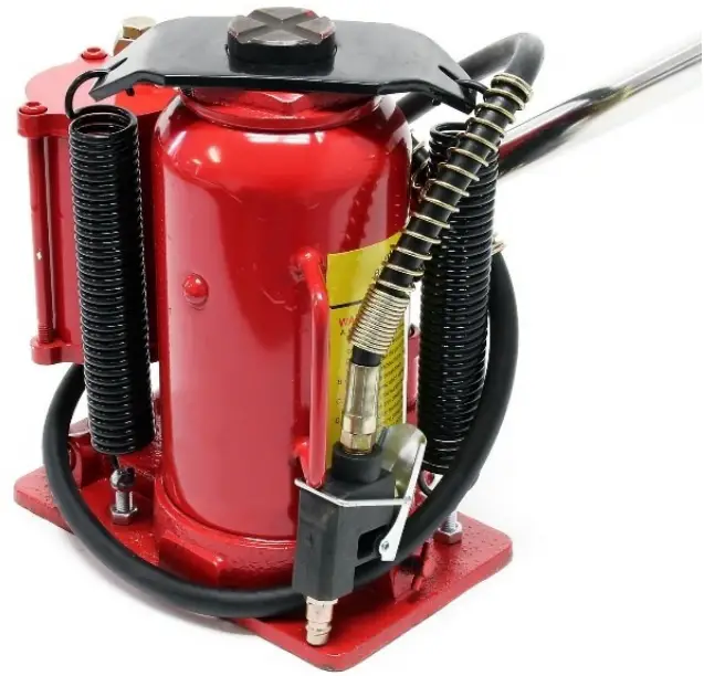
Read and follow the operating instructions and safety information before using for the first time.
Technical changes reserved!
Due to further developments, illustrations, functioning steps, and technical data can differ insignificantly.
Updating the documentation
If you have suggestions for improvement or have found any irregularities, please contact us.
Introduction
Thank you for purchasing this quality product. To minimise the risk of injury we urge that our clients take some basic safety precautions when using this device. Please read the operation instructions carefully and make sure you have understood its content. Keep these operation instructions safe.
For your safety and the safety of others around you, read these instructions carefully before assembling, servicing, or using the jack. Regard all safety information and warnings. Always wear safety glasses when operating this product. Failure to comply with the information stated could result in severe, even fatal injury and/or property damage.
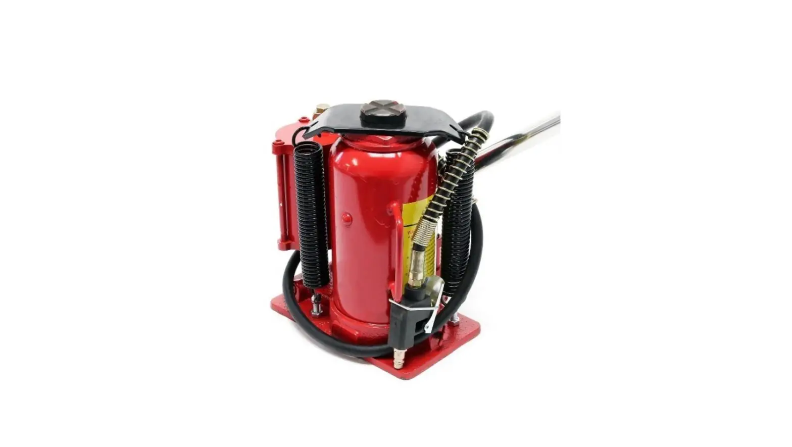
Description of the product
Hydraulic jacks are designed for lifting, but not sustaining loads. Respect the rated capacity of the individual jack (item 61974: 12 t; item 61975: 20 t). They can be used vertically or angled up to 5° from the vertical position. After lifting, the loads must immediately be supported by appropriate means. Each model is suitable for use in an appropriately rated and designed vertical or bench press structure. These jacks are not recommended for use in lifting or positioning houses and/or building structures. These jacks comply with applicable standards. For air actuated use, ensure an air supply.
| Item № | Lifting ca- pacity (t) | Min. height (㎜) | Max. height (㎜) | Lifting height (㎜) | Regular height (㎜) | Net weight (㎏) |
| 61974 | 12 | 250 | 495 | 165 | 80 | 11.75 |
| 61975 | 20 | 260 | 510 | 170 | 80 | 14.82 |
Before use
- Verify that the product and the application are compatible. Contact the manufacturer or an authorised service partner.
- Before using this product, read the operating manual completely and familiarise yourself with the product thoroughly and the hazards associated with its improper use.
- Open the release valve (not more than 2 full turns counter-clockwise).
- With the ram fully retracted, locate and remove the oil filler plug. Insert the handle into the hand sleeve, then pump 6–8 strokes. This will help release any pressurised air which may be trapped within the reservoir. Ensure the oil level is just below the oil filler plug hole. Re-install the oil filler plug.
- Pour a teaspoon of good quality air tool lubricant into the air supply inlet of the lift control valve. Connect to air supply and operate 3 s to evenly distribute the lubricant.
- Check to ensure that the jack rolls freely (if equipped with) and that the pump operates smoothly before putting it into service. Replace worn or damaged parts and assemblies with original spare parts from the manufacturer.
- This product is fitted for the common ¼″ NPT pressurised air plug nipple. When installing the ¼″ NPT nipple of your choice, ensure that thread tape or compound is used when servicing connections.
- Inspect before each use. Do not use if components are bent, broken, or cracked. Broken parts must be repaired before the jack is taken into action again.
Operation
Lifting
- First insert the notched end of the handle into the release valve.
- Secure the load to prevent inadvertent shifting and movement.
- Position the jack near desired lifting point.
- Close the release valve by turning the handle clockwise until it is firmly closed.
Caution: Use the handle provided with this product or an authorized replacement handle to ensure proper release valve operation. Do not use an extender on the air hose nor the operating handle when using to lift vehicles. Lift only on the manufacturer’s recommended lift point and in accordance with the published guidelines in your vehicle owner’s manual. Always use the jack stands to support the load. - Hold the handle safely at the end. Pump the handle or press the release valve until the load touches the ram. To stop the air operation, simply remove the handle of the valve. Only activate/deactivate the hoist control valve by hand.
- Raise load to desired height, then immediately transfer the load to appropriately-rated support devices such as jack stands.
Caution: This is a lifting device only. It is designed to lift a part of the total vehicle (one wheel or axis). Always wear safety glasses when using this equipment. Centre the load on the ram before lifting it. Never work on, under or around load until it is properly supported. Transfer the load immediately to appropriately rated jack stands. Do not use this product for any purpose OTHER THAN that for which it was intended. It is the owner’s responsibility to keep labels and instructional material legible and available. Replacement labels and manuals are available from the manufacturer. Failure to heed these and all other warnings pertaining to this product can result in sudden loss of lifted load resulting in death, personal injury and/ or property damage.
Lowering
- Raise the load enough to carefully remove the jack stands.
- Insert handle onto release valve and slowly turn the handle counter clockwise, but not more than half a turn. If load fails to lower, carefully transfer the load to another lifting device and jack stands. Carefully remove the affected jack, then the jack stands. Lower the load again by slowly turning the release valve no more than half a turn.
Caution: Be sure all tools and personnel are clear before lowering the load. Dangerous dynamic shock loads are created by quickly opening and closing the release valve while the load is being lowered. The resulting overload may cause hydraulic system failure which could cause severe personal injury and/ or property damage. - After removing the jack from under the load, push the ram and handle sleeve down to reduce exposure to rust and contamination.
Maintenance
Important: Use only a good grade hydraulic oil. Avoid mixing different types of fluid and never use brake fluid, turbine oil, transmission fluid, motor oil or glycerine.
Adding oil
- With the ram saddle fully lowered and pump piston fully depressed, set jack in its upright level position and remove the oil filler plug.
- Fill until oil is level with the filler plug hole and reinstall the oil filler plug
Changing oil
For best performance and longest life, replace the complete fluid supply at least once a year.
- With the ram saddle fully lowered and pump piston fully depressed remove the oil filler plug.
- Lay the jack on its side and drain the fluid into a suitable container.
Note: Dispose hydraulic fluid environmentally friendly in accordance with local regulations. - Refill with good quality jack oil. Reinstall oil filler plug.
Lubrication
- A coating of light lubricating oil to pivot points, axles and hinges will help prevent rust and assure that wheels, casters, and pump assemblies move freely.
- Periodically check the pump piston and ram for signs of rust or corrosion. Clean as needed and wipe with an oily cloth. Caution: Never use sandpaper or abrasive material on these surfaces.
- When not in use, store the jack with pump piston and ram fully retracted.
Troubleshooting
Problem | Possible causes | Solutions |
| Jack will not lift load | Release valve not closed tightly | Ensure that release valve is tightly closed. |
| Overload | Remedy overload. | |
| Air supply inadequate | Ensure adequate air supply. | |
| Jack bleeds off after lift | Release valve not closed tightly | Ensure that release valve is tightly closed. |
| Overload | Remedy overload. | |
| Hydraulic unit malfunction | Contact qualified person. | |
| Jack will not lower after unloading | Reservoir overfilled | Drain fluid to proper level. |
| Linkages binding | Clean and lubricate moving parts. | |
| Poor lift performance | Fluid level low | Ensure proper fluid level. |
| Air trapped in system | With ram fully retracted, remove oil filler plug to let pressurized air escape; reinstall oil filler plug. | |
| Will not lift to full extension | Fluid level low | Ensure proper fluid level. |
Exploded views
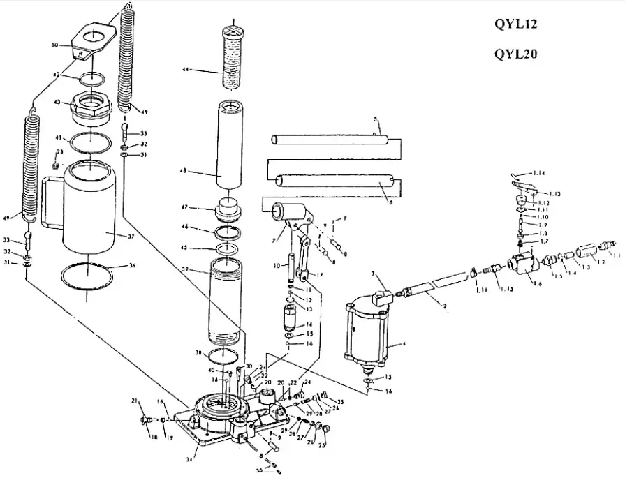
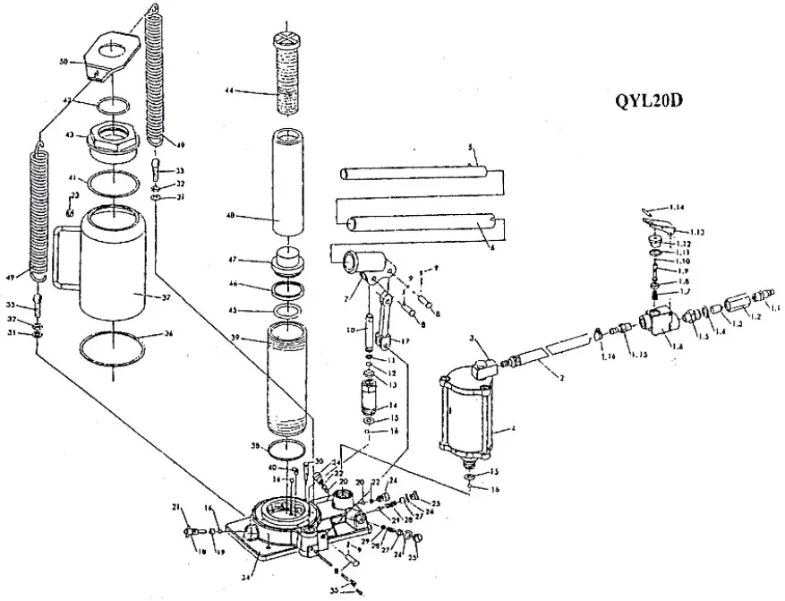
Parts list
| No | Name | Qty. | |
| 1.1 | Hose connector | 1 | |
| 1.2 | Connecting nut | 1 | |
| 1.3 | Air filter | 1 | |
| 1.4 | O-ring 18×2.4 | 1 | |
| 1.5 | Connector | 1 | |
| 1.6 | Valve body | 1 | |
| 1.7 | Spring | 1 | |
| 1.8 | Packing | 1 | |
| 1.9 | Throttle | 1 | |
| 1.1 | O-ring 3×1.6 | 1 | |
| 1.11 | O-ring 18×2.4 | 1 | |
| 1.12 | Nut | 1 | |
| 1.13 | Lever | 1 | |
| 1.14 | Lever ring | 1 | |
| 1.15 | Hose connector | 1 | |
| 1.16 | Hose band | 2 | |
| 2 | Air hose | 1 | |
| 3 | Connector | 1 | |
| 4 | Air pump | 1 | |
| 5 | Upper handle | 1 | |
| 6 | Lower handle | 1 | |
| 7 | Plunger | 1 | |
| 8 | Shaft pin | 3 | |
| 9 | Cotter pin | 3 | |
| 10 | Pump plunger | 1 | |
| 11 | Pump plunger retainer | 1 | |
| 12 | O-ring | 1 | |
| 13 | Dust proof ring | 1 | |
| 14 | Pump reservoir | 1 | |
| 15 | Copper washer | 1 | |
| 16 | Steel ball 6 | 6 | |
| 17 | Hydraulic cylinder | 1 | |
| 18 | Release valve screw | 1 | |
| 12D | 20W | ||
| 20D | |||
| 19 | Release valve seal | 1 | |
| 20 | Steel ball 6.35 | 1 | |
| 21 | Pin | 1 | |
| 22 | Valve spring | 2 | |
| 23 | Filler plug | 1 | |
| 24 | Screw | 2 | |
| 25 | Plug screw | 1 | 2 |
| 26 | Plug washer | 1 | 2 |
| 27 | Overload valve screw | 1 | 2 |
| 28 | Safety valve spring | 1 | 2 |
| 29 | Overload tapering valve | 1 | 2 |
| 30 | Filter net | 2 | |
| 31 | Spring washer 8 | 2 | |
| 32 | Nut 8 | 2 | |
| 33 | Bolt M8×35 | 2 | |
| 34 | Basis | 1 | |
| 35 | Plug screw | 4 | |
| 36 | Cylinder bottom seal | 1 | |
| 37 | Reservoir | 1 | |
| 38 | Packing | 1 | |
| 39 | Cylinder | 1 | |
| 40 | Steel ball retainer | 2 | |
| 41 | Cylinder top seal | 1 | |
| 42 | O-ring | 1 | |
| 43 | Top nut | 1 | |
| 44 | Extension screw | 1 | |
| 45 | O-ring | 1 | |
| 46 | O-ring returner | 1 | |
| 47 | Ram header | 1 | |
| 48 | Ram | 1 | |
| 49 | Spring | 2 | |
| 50 | Spring plate | 2 | |
| 1.1 | Tube connector | 1 | |
| 1.2 | O-ring | 2 | |
| 1.3 | Removable base | 1 | |
| 1.4 | Split washer | 1 | |
| 2 | Hex socket screw | 3 | |
| 3 | Cover | 1 | |
| 4 | Washer | 2 | |
| 5 | Air pump body | 1 | |
| 6 | Spring washer | 3 | |
| 7 | Seal | 2 | |
| 8 | O-ring 63.5×3.55 | 2 | |
| 9 | Square ring | 1 | |
| 10 | Piston | 1 | |
| 11 | Nut M5 | 1 | |
| 12 | Block | 1 | |
| 13 | Plunger | 1 | |
| 14 | Spring | 1 | |
| 15 | Nut | 1 | |
| 16 | Packing guide | 1 | |
| 17 | NL retainer | 1 | |
| 18 | Y-seal | 1 | |
| 19 | Cover | 1 | |
| 20 | Adjusting nut | 1 | |
| 21 | Plunger cover | 1 | |
Air motor – exploded view and parts list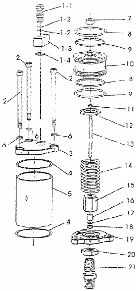
The Tool Experts The information contained in this document may alter at any time without previous notice. It is prohibited to copy or spread any parts of this document in any way without prior written allowance. All rights reserved.
The WilTec Wildanger Technik GmbH cannot be held accountable for any possible mistakes in this operating manual, nor in the diagrams and figures shown.
Even though, the WilTec Wildanger Technik GmbH has undergone biggest possible efforts to ensure that the operating manual is complete, faultless, and up to date, mistakes cannot be entirely avoided. If you should find a mistake or wish to make a suggestion for improvement, we look forward to hearing from you.
Send an e-mail to: [email protected]
or use our contact form: https://www.wiltec.de/contacts/
The most recent version of this manual in various languages can be found in our online shop via: https://www.wiltec.de/docsearch
Our postal address is:
WilTec Wildanger Technik GmbH
Königsbenden 12
52249 Eschweiler
Germany
To return orders for exchange, repair, or other purposes, please use the following address. Attention! To allow for a smooth execution of your complaint or return, it is important to contact our customer service team before returning the goods.
Returns Department
WilTec Wildanger Technik GmbH
Königsbenden 28
52249 Eschweiler
E-mail: [email protected]
Tel: +49 2403 55592–0
Fax: +49 2403 55592–15
Important notice:
The reprint or reproduction, even of excerpts, and any commercial use, even in part, of this instruction manual require the written permission of WilTec Wildanger Technik GmbH.