![]() VR Series
VR Series
Power Conversion Modules
Overview:
The unit converts a 24VAC and/or 24VDC input into a regulated 5VDC or 12VDC output.
Reference Chart:
| Altronix Model Number | Input | Output | Battery Charging | Cable Assembly | Screw Terminal | Spring Terminal |
| VR1 | 24VAC/20VA or higher / 24VDC | 12VDC 0 1A max. | — | ✓ | — | — |
| VR1T | 24VAC/20VA or higher / 24VDC | 12VDC 0 1A max. | — | — | — | ✓ |
| VR2T | 24VAC/20VA or higher / 24VDC | 12VDC 0 0.5A max. | — | — | — | ✓ |
| VR3T | 24VDC | 12VDC 02A max. | — | — | ✓ | — |
| VR4T | 24VDC | 12VDC 03A max. | — | — | ✓ | — |
| VR5T | 24VAC/50VA or higher / 24VDC | 12VDC 03A max. | — | — | — | ✓ |
| VR5BT | 24VAC/50VA or higher / 24VDC | 12VDC 03A max. | ✓ | — | — | ✓ |
| VR1TM5 | 16VAC/24VAC/20VA or higher /12 or 24VDC | 5VDC ®1A max. | — | — | — | ✓ |
Specifications: 
Agency Listing:
- CE European Conformity.
Input:
- Input 24VAC or 24VDC.
Output:
- 5VDC (VR1TM5) or 12VDC output.
- Filtered and electronically regulated output.
- Built-in overload protection.
Applications:
- Power for 12VDC CCTV cameras and accessories,
Fiber Optic Transmitters, REX PIR’s, Prox Readers, etc.
Visual Indicators:
- Power LED indicator.
Features:
- Modular connector/cable assembly facilitates ease of wiring.
- Compact design allows for integration in a wide range of camera housings.
Dimensions (W x D x H approx.):
VR5T / VR5BT:
3.375” x 2.5” x 1.125” (85.7mm x 63.5mm x 28.6mm) All other units:
1.625” x 2.375” x 1” (41.3mm x 60.3mm x 25.4mm)
Installation Instructions:
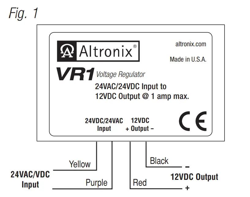
Installing VR1 (Fig. 1, pg. 1):
- Mount unit in proximity to the device. Affix one side of velcro (supplied) to the unit and place the second side of the velcro in the desired location.
- Connect Yellow lead and Purple lead to 24VAC transformer or 24VDC power source*.
- Measure output voltage and check polarity before connecting devices, in order to avoid potential damage.
- Connect Red lead [Pos. +] and Black lead [Neg. –] to device to be powered.
- LED will illuminate when power is present.
* For CE compliance use a Class 2 Power-Limited Power Source.
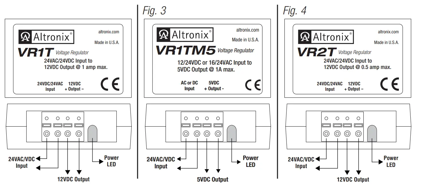
Installing VR1T, VR1TM5, VR2T (Figs. 2-4, pg. 2):
- Mount unit in proximity to the device. Affix one side of velcro (supplied) to unit and place the second side of the velcro in the desired location.
- Connect 24VAC transformer or 24VDC source* to the terminals marked [24VDC/24VAC Input].
- Measure output voltage and check polarity before connecting devices, in order to avoid potential damage.
- Connect device to be powered to the terminals marked [+ Output –].
- LED will illuminate when power is present.
* For CE compliance use a Class 2 Power-Limited Power Source.
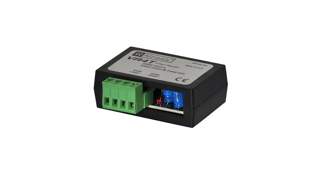
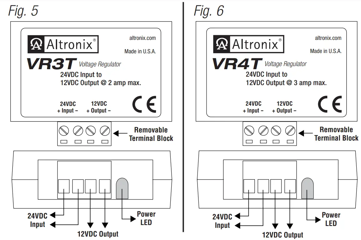
Installing VR3T, VR4T (Figs. 5-6, pg. 2):
- Mount unit in proximity to the device. Affix one side of velcro (supplied) to the unit and place the second side of the velcro in the desired location.
- Connect 24VDC source* to the terminals marked [24VDC + Input –].
- Measure output voltage and check polarity before connecting devices, in order to avoid potential damage.
- Connect device to be powered to the terminals marked [– Output +].
- LED will illuminate when power is present.
* For CE compliance use a Class 2 Power-Limited Power Source.
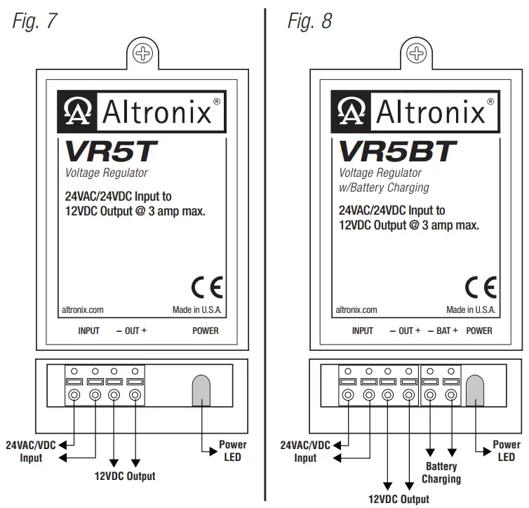
Installing VR5T, VR5BT (Figs. 7-8, pg. 2):
- Mount unit in proximity to the device. Use a proper fastener and/or wall anchor when securing unit to the wall.
- Connect 24VAC transformer or 24VDC source* to the terminals marked [Input].
- Measure output voltage and check polarity before connecting devices, in order to avoid potential damage.
- Connect device to be powered to the terminals marked [– OUT + ].
- LED will illuminate when power is present.
- For VR5BT (Fig. 8, pg. 2) – when the use of stand-by batteries is desired, they must be lead acid or gel type. Connect battery to terminals marked [– BAT +].
* For CE compliance use a Class 2 Power-Limited Power Source.
Altronix is not responsible for any typographical errors.
Product specifications are subject to change without notice.
140 58th Street, Brooklyn, New York 11220 USA |
phone: 718-567-8181 |
fax: 718-567-9056 web site: www.altronix.com |
e-mail: [email protected] |
Lifetime Warranty |
Made in U.S.A. IIVRseries – Rev. 070709 F23U![]()


