![]() TJ-56-513B Heart Shaped 4Bit Digital Clock DIY Kit
TJ-56-513B Heart Shaped 4Bit Digital Clock DIY Kit
User Manual
Introduction:
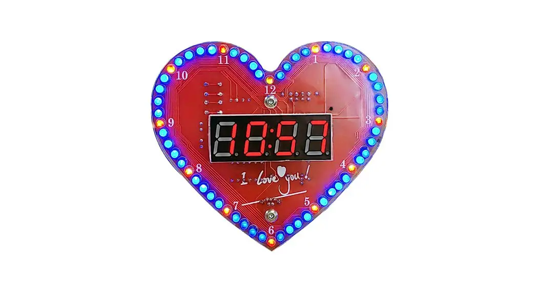
TJ-56-513B is a Heart Shaped Rotating Led 4Bit Digital Electronic Clock DIY Kit.
It will display current date, time, temperature in the real time, hourly reminder, alarm clock music and led animation. User can set alarm as your needs. It is easy to operate, beautiful design, very suitable for home or office environment.
Feature:
- >Exquisite design
- >Red-Blue led flashing display
- >Red 4 Bit Digital display
- >Automatic brightness adjustment
- >Time/Date/Alarm/Temperature
- >Adjustable alarm clock music/LED animation modes
- >Time memory function
- >Temperature value can be calibrated
- >Hourly Reminder
- >DIY manual soldering
Parameter:
- >Item name: TJ-56-513B Heart Shaped Rotating Led 4Bit Digital Electronic Clock DIY Kit
- >Model:TJ-56-513B
- >Work voltage: DC 5V
- >Display color: Red
- >Work Temperature:-20℃~85℃
- >Work Humidity:0%~95%RH
- >Size(Installed):100*90*13mm
Main Function:
- >Display time: Hour, Minute, Second.
- >Display date: Year, Month, Day.
- >Display Week.
- >Display current temperature in Celsius.
- >Adjustable alarm clock music: 4 music.
- >Hourly Reminder
- >Automatic brightness adjustment.
- >Adjustable volume.
- >Set LED display mode.
- >Calibration temperature display value.
Set Method:
- >It displays the current time by default in hour-minute. Note:
- >Press S1 button to display month-day, week, year. Press S2 button to display temperature, alarm time, minute-second.
- >Short press S1 and S2 at the same time to switch the LED display mode. A total of 12 display modes.
4> .Set Method:
4.1> Keep press two buttons about 7 second enter into set mode.
4.2>Short press S1 button to switch set mode from Fu-1 to Fu-5. The parameter 1~5 will flash automatically.
4.3>.Short press S2 button to selected mode.
4.4> The selected or setting parameters will flash automatically.
4.5> 81 button is used to change value. Note: The value just can increase and then start to increase again.
4.6>S2 button is used to set parameter or confirm selected.
5>.Fu-1 mode: Set time in Hour: Minute.
5.1>.Set Hour: Short press S1 button to set value for current hour.
5.2>.Set Minute: Short press S2 button to select set for minute. And then press $1 button to set value for current minute.
5.3>.Press S2 button again to save and exit set mode.
6>.Fu-2 mode: Set date in Month, Day and Year.
6.1>.Set Month: Short press S1 button to set value for current month.
6.2>.Set Day: Short press S2 button to select set for day. And then press S1 button to set value for current day.
6.3>.Set Day: Short press S2 button to select set for year. And then press S1 button to set value for current year. It can display from 2000 to 2099.
6.4> Press S2 button again to save and exit set mode.
7>.Fu-3 mode: Set alarm time in Hour: Minute.
7.1>.Set Hour: Short press S1 button to set value for alarm hour. Note: the hour can be set 24 which means tumen OFF alarm.
7.2>.Set Minute: Short press S2 button to select set for minute. And then press $1 button to set value for alarm minute.
7.3>.Press S2 button again to save and exit set mode.
8>.Fu-4 mode: Set Hourly Report, Display Mode, Set Brightness.
8.1>.It can display 4bit: The first bit is used to set Hourly Report. The second bit is used to set Display Mode and the last two bit are used to set Brightness.
8.2>.Set Hourly Report:
8.2.1>.Short press S1 button to disable and enable Hourly Report function.
8.2.2>. 1″ means enable Hourly Report function.
8.2.3>. ‘0″ means disable Hourly Report function.
8.3>.Set Display Mode:
8.3.1>.Short press S2 button to select set the second bit to set display mode.
And then press S1 button to switch display mode.
8.3.2>. ‘0″ means just display time.
8.3.2>. 1″ means display time and interval display temperature.
The interval time is about 59 second and display temperature in 1 second. That is, the temperature is displayed for 1 second every minute.
8.3.3>. “2’ means display time and interval display date and temperature.
The interval time is about 58 second and display date in 1 second and display temperature in 1 second. That is, the temperature and date are displayed for 1 second each minute.
8.3.4>. ” 3″ means just display temperature. Note: In this mode, user can calibration temperature value at normal display interface by two buttons. Press S1 or S2 arbitrarily once to display the temperature correction value. Press S1 again to increase the correction value, and press S2 to decrease the correction aloe. Note that the correction value can be negative. After a period of time without pressing the button, save the correction value and return to the temperature display state.
8.4>.Set Brightness.
8.4.1>.Short press S2 button to select set the last two bits to set display brightness. And then press S1 button to switch display mode.
8.4.2>. ‘A’ means the display brightness is automatically adjusted according to the ambient brightness.
843>. 1″to ‘15 means seethe brightness level. The brightness of the display will not change.
8.5>.Press S2 button again to save and exit set mode.
8.6>.Eg. ‘1215° means: Enable Hourly Report function; Display time and interval display date and temperature; The brightness level is 15.
9> Fu-5 mode: set Alarm Clock Music, set Volume.
9.1>.Set Alarm Clock Music: Short press S1 button to select 4 music.
9.2>.Set Day: Short press S2 button to select set volume. And then press S1 button to set volume value from ‘2″ to ‘40″ . Maximum volume when ‘40’ is displayed.
9.3>.Press S2 button again to save and exit set mode.
Note:
3>.If the backup battery is removed after the power failure, the saved Settings will be lost and may also display garbled codes, which can be displayed correctly after setting again display mode at first.
Component listing:
| NO. | Component Name | PCB Marker | Parameter | QTY |
| 1 | Metal Film Resistor | R10,R11,R14,R15 | 10Kohm | 4 |
| 2 | Metal Film Resistor | R12 | 100Kohm | 1 |
| 3 | Metal Film Resistor | R9 | 100ohm | 1 |
| 4 | Metal Film Resistor | R1-R18 | 330ohm | 8 |
| 5 | Metal Film Resistor | R13 | 200Kohm | 1 |
| 6 | Black Button | S1,S2 | 6*6*5mm | 2 |
| 7 | Diode | ID1 | 1N4148 | 1 |
| 8 | micro-USB Socket | USB | 1 | |
| 9 | DS1302 IC | U2 | 8PIN | 1 |
| 10 | IC Socket | U2 | 8PIN | 1 |
| 11 | S8550 Transistor | Q1 | 1 | |
| 12 | 0.56in 4Bit Digital Tube | SMG | RED | 1 |
| 13 | Ceramic Capacitor | C1,C2 | 5pF | 2 |
| 14 | Ceramic Capacitor | C3 | 0.1uF 104 | 1 |
| 15 | Electrolytic Capacitor | C4 | 220uF 10y | 1 |
| 16 | Buzzer | SPEAKER | 1 | |
| 17 | 5516 Photoresistor | GM | 1 | |
| 18 | Crystal Oscillator | Y1 | 32.768KHz | 1 |
| 19 | Thermistor | RM | 10Kohm NTC | 1 |
| 20 | CR1220 Battery | J2 | 3V | 1 |
| 21 | CR1220 Battery Socket | J2 | SMD | 1 |
| 22 | STC15W408AS Chip | U1 | SOP-28 | 1 |
| 23 | RED LED Diode Light | 12 | ||
| 24 | BLUE LED Diode Light | 48 | ||
| 25 | M3 Screw | 4 | ||
| 26 | Copper Posts | 2 | ||
| 27 | Nut | 2 | ||
| 28 | PCB | 1 | ||
| 29 | Acrylic Board | 2 | ||
| 30 | USB Power Wire | 1 | ||
| Note: Users can complete the installation according to the PCB silk screen and component list. | ||||
Application:
- > Practical at home
- > Indoor display
- >.Simple appearance, easy office
- > Wall decoration
Installation Tips:
- > User needs to prepare the soldering tool at first.
- > Please be patient until the installation is complete.
- > The package is DIY kit. It need finish install by user.
- > The soldering iron can’t touch the components for a long time(1.0 second), otherwise it will damage the components.
- > Pay attention to the positive and negative of the components.
- > Strictly prohibit short circuit.
- > Install complex components preferentially.
- > Make sure all components are in right direction and right place.
- > Please wear anti-static gloves or anti-static wristbands when installing electronic components.
- > It is strongly recommended to read the installation manual before starting installation!!!
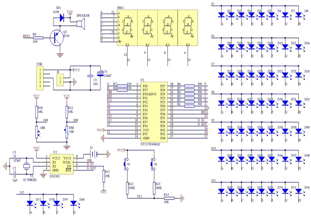
Circuit Diagram
Installation Steps(Please be patient install
- >.Step 1: Install 4pcs 10Kohm Metal Film Resistor at R10,R11,R14,R15.
- > Step 2: Install 8pcs 330ohm Metal Film Resistor at R1-R8.
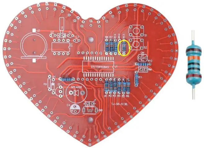
- >.Step 3: Install 1pcs 200Kohm Metal Film Resistor at R13.
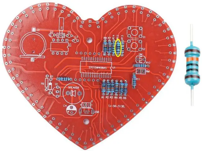
- > Step 4: Install 1pcs 100Kohm Metal Film Resistor at R12.
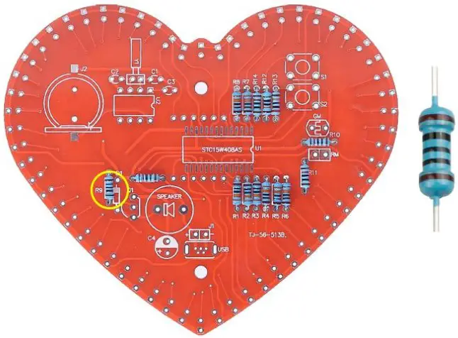
- > Step 5: Install 1pcs 100ohm Metal Film Resistor at R9.
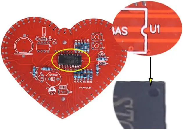
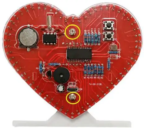
- >.Step 6: Install 1pcs SOP-28 Chip STC15W408AS at U1. There is a mark(circle silk screen printing) on one end of the Chip and there is a mark(curved silk screen printing) on PCB where the Chip can place on. These two marks are corresponding to each other and are used to specify the installation direction of the Chip.
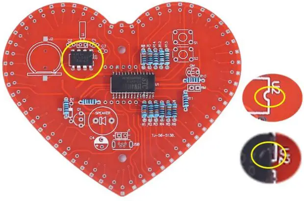
- >.Step 7: Install 1pcs DS1302 Chip at U2. There is a mark(notch) on one end of the chip and there is a mark(curved silk screen printing) on PCB where the IC can place on. These two marks are corresponding to each other and are used to specify the installation direction of the IC. We also provided 1pcs IC Socket, if you need, you can also use the same method, the notch mark of Socket corresponding to the PCB mark, first install the Socket on U2, and then install the chip on the Socket.
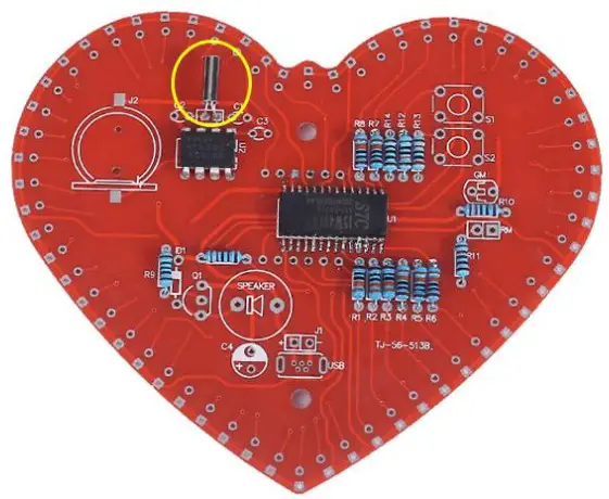
- >.Step 8: Install 1pcs 32.768K Crystal Oscillator at Y1.
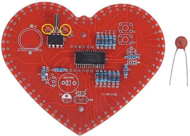
- > Step 9: Install 2pcs 5pF Ceramic Capacitor at C1,C2.
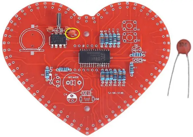
- >.Step 10: Install 1pcs 0.1uF 104 Ceramic Capacitor at C3.
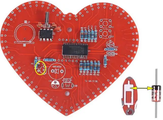
- >.Step 11: Install 1pcs 1N4148 Diode at ID1. Pay attention to the installation direction. Note: The black mark on Diode and the white mark on PCB are corresponding.
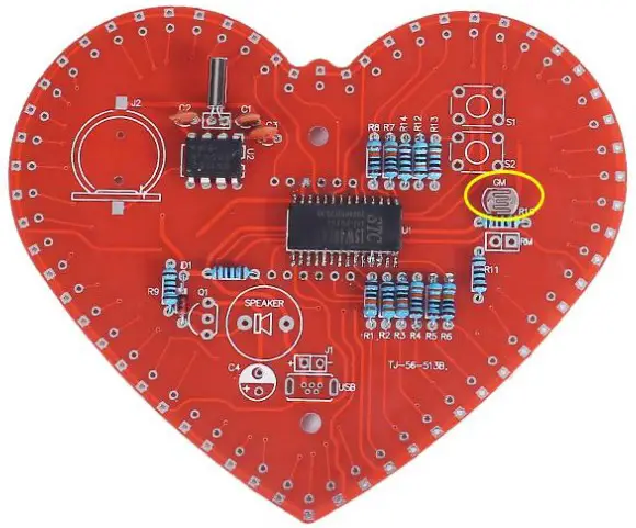
- >.Step 12: Install 1pcs 5516 Photoresistor at GM.
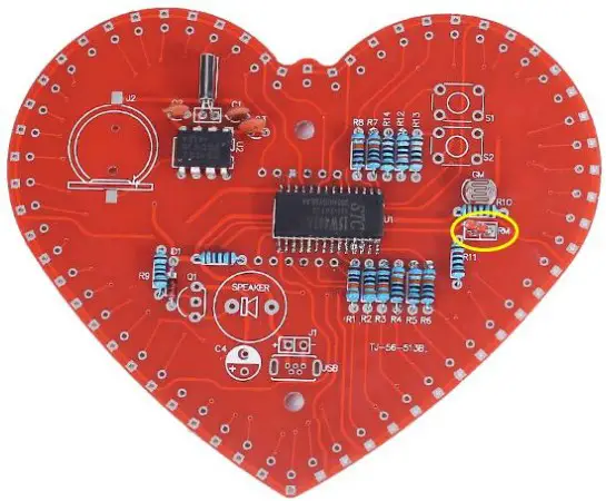
- >.Step 13: Install 1pcs 10K NTC Thermistor at RM.
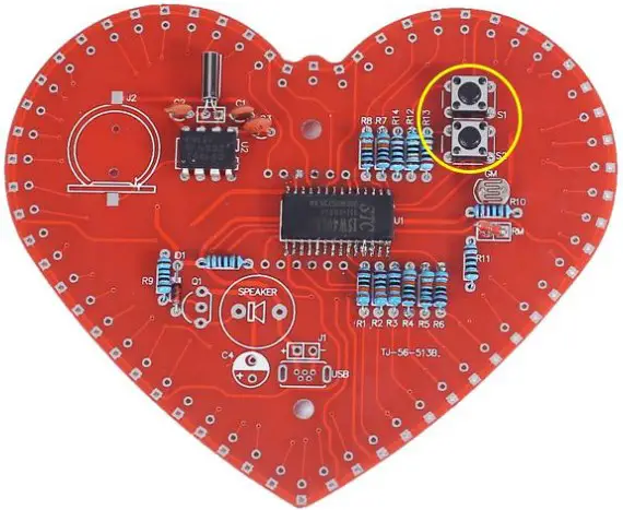
- >.Step 14: Install 2pcs 6*6*5mm Black Button at $1,S2.
- >_.Step 15: Install 1pcs S8550 Transistor at Q1. Pay attention to the installation direction of arc.
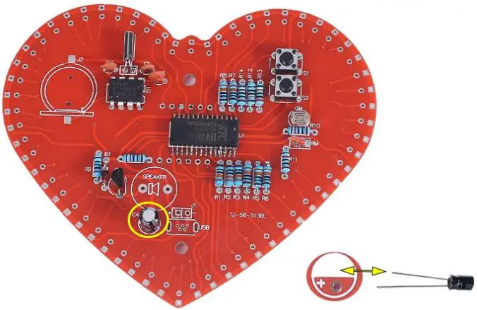
- >.Step 16: Install 1pcs 220uF Electrolytic Capacitor at C4. Pay attention to distinguish between positive and negative. The shorter pin is negative pole and insert into white pad.
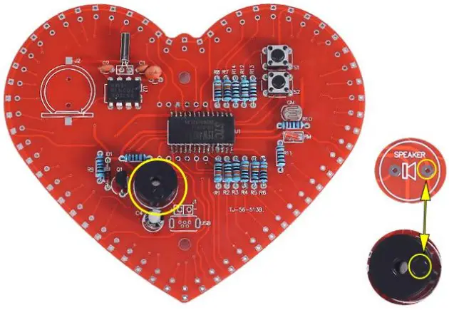
- >.Step 17: Install 1pcs Passive buzzer at SPEAKER. Pay attention to the installation direction.
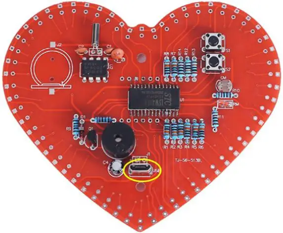
- >.Step 18: Install 1pcs micor-USB Socket at USB.
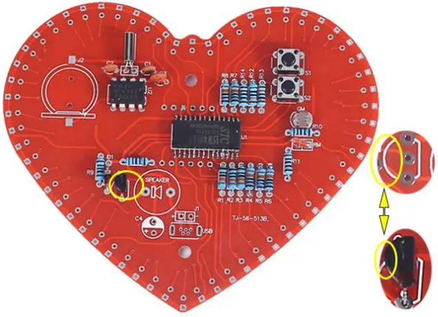
- >.Step 19: Install 1pcs CR1220 Battery Socket at J2.
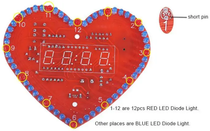
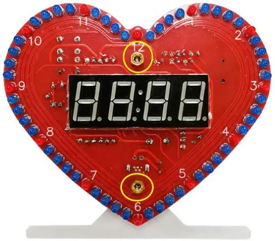
- >.Step 20: Install 12pcs RED LED Diode Light and 48pcs BLUE LED Diode Light on PCB another side. Pay attention to distinguish between positive and negative.
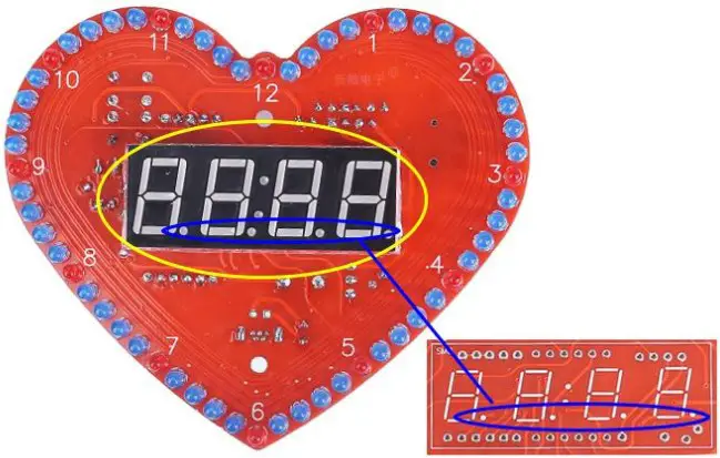
The shorter pin is negative pole. - >.Step 21: Install 1pcs 0.56in 4Bit Digital Tube at SMG on PCB another side. Pay attention to the installation direction of the decimal point.
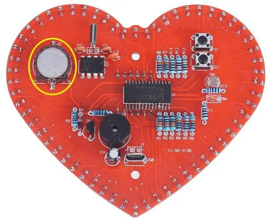
- >.Step 22: Install 1pcs 3V CR1220 Battery on battery socket. Pay attention to the direction of the battery.
- >.Step 23: Tear off the yellow protective film on the transparent acrylic surface.
- > Step 24: Connect the PCB and the bottom acrylic board by 2pcs longer M3 Screw.
- >_.Step 25: Fixed the screws with 2pcs copper posts.
- >.Step 26: Connect the PCB and front acrylic board by 2pcs shorter M3 Screw.
- >.Step 27: Connect to power supply and set parameters according to set method.
Install shown steps:
Step 1: Install 4pcs 10Kohm Metal Film Resistor at R10,R11,R14,R15.
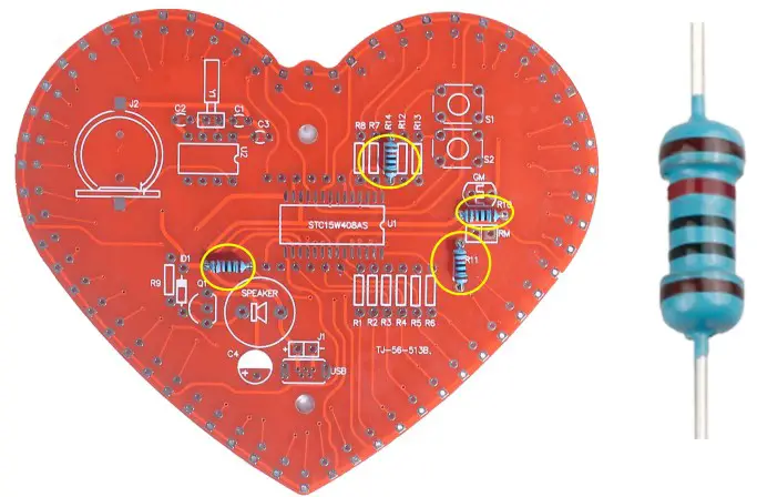
Step 2: Install 8pcs 3300hm Metal Film Resistor at R1-R8.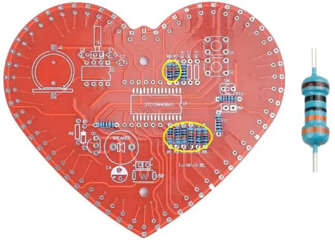
Step 3: Install 1pcs 200Kohm Metal Film Resistor at R13.
Step 4: Install 1pcs 100Kohm Metal Film Resistor at R12.
Step 5: Install 1pcs 100ohm Metal Film Resistor at R9.
Step 6: Install 1pcs SOP-28 Chip STC15W408AS at U1. There is a mark (circle silk screen printing) on one end of the Chip and there is a mark (curved silk screen printing) on PCB where the Chip can place on. These two marks are corresponding to each other and are used to specify the installation direction of the Chip.
Step 7: Install 1pcs DS1302 Chip at U2. There is a mark (notch) on one end of the chip and there is a mark (curved silk screen printing) on PCB where the IC can place on. These two marks are corresponding to each other and are used to specify the installation direction of the IC.
Step 8: Install 1pcs 32.768K Crystal Oscillator at ¥1
Step 9: Install 2pcs 5pF Ceramic Capacitor at C1,C2.
Step 10: Install 1pcs 0.1uF 104 Ceramic Capacitor at C3.
Step 11: Install 1pcs 1N4148 Diode at ID1. Pay attention to the installation direction. Note: The black mark on Diode and the white mark on PCB are corresponding.
Step 12: Install 1pcs 5516 Photoresistor at GM.
Step 13: Install 1pcs 10K NTC Thermistor at RM.
Step 14: Install 2pcs 6*6*5mm Black Button at $1,S2.
Step 15: Install 1pcs S8550 Transistor at Q1.
Pay attention to the installation direction of arc.
Step 16: Install 1pcs 220uF Electrolytic Capacitor at C4.
Pay attention to distinguish between positive and negative.
The shorter pin is negative pole and insert into white pad.
Step 17: Install 1pcs Passive buzzer at SPEAKER.
Pay attention to the installation direction.
Step 18: Install ipcsmicor-USB Socket at USB.
Step 19: Install 1pcs CR1220 Battery Socket at J2.
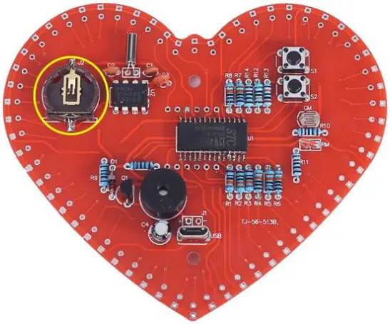
Step 20: Install 12pcs RED LED Diode Light and 48pcs BLUE LED Diode Light on PCB another side.
Pay attention to distinguish between positive and negative.
The shorter pin is negative pole.
Step 21: Install 1pcs 0.56in 4Bit Digital Tube at SMG on PCB another side.
Pay attention to the installation direction of the decimal point.
Step 22: Install 1pcs 3V CR1220 Battery on battery socket.
Pay attention to the direction of the battery.
Step 23: Tear off the yellow protective film on the transparent acrylic surface.

Step 24: Connect the PCB and the bottom acrylic board by 2pcs longer M3 Screw.
Step 25: Fixed the screws with 2pcs copper posts.
Step 26: Connect the PCB and front acrylic board by 2pcs shorter M3 Screw.
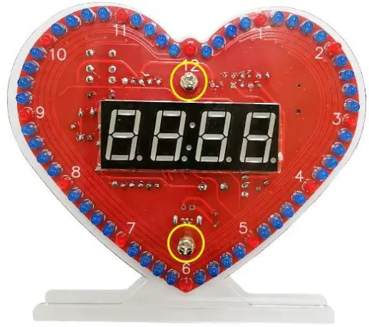
![]()


