Big Stream 2 Quick Guide
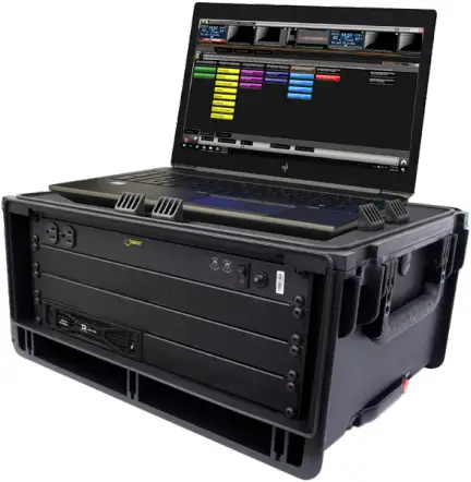
This guide explains the setup of a Daktronics “Big Stream 2” system. This portable system includes a Digital Media Player (DMP) that provides an NDI (Network Device Interface) video output to a compatible customer-provided streaming device. Content is created and played using the Daktronics Show Control System. For more information about Show Control System installation, registration, or operation, refer to the documentation provided with the software. Refer also to the following YouTube playlist: https://www.youtube.com/watch?v=vbXFr2aSrnM&list=PL2dNnauPijWWHWyn9LKphHE0SjkkkwJP3
Refer to DWG-4694089 for rack schematics and DWG-4694090 for rack specifications. Site-specific diagrams may also be available; these will take precedence over any general instructions found in this guide. Contact the Daktronics Standard Order Project Manager (SOPM) or Standard Order Project Coordinator (SOPC) to ask if any site-specific drawings exist for the project.
Equipment Setup
1. Unpack all items and verify everything from the Bill of Materials (BOM) is included.
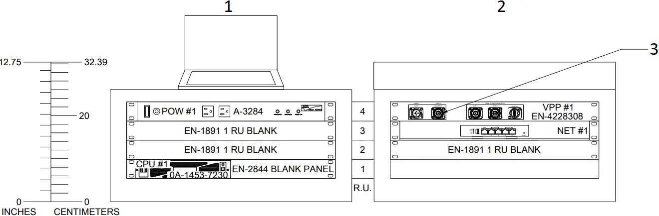
2. Place the portable control rack at the desired operator location, and remove the cover panels to access the internal components and connections.
3. Place the Show Control laptop on the top shelf of the rack case, and use the plastic clamps to hold it in place.
4. Route the supplied Cat5 network cable through the hole in the top of the rack case and connect it to the Show Control laptop’s network jack.
Notes:
- If the Show Control laptop will be located elsewhere, a 100′ Cat5 network cable is supplied for this purpose.
- An Internet (WAN) connection into the network router in the rack is required to output the streaming video online.
5. Bring a video source into the appropriate input jack on the rear of the rack.
- SDI: Connect to the SDI INPUT jack on VPP #1.
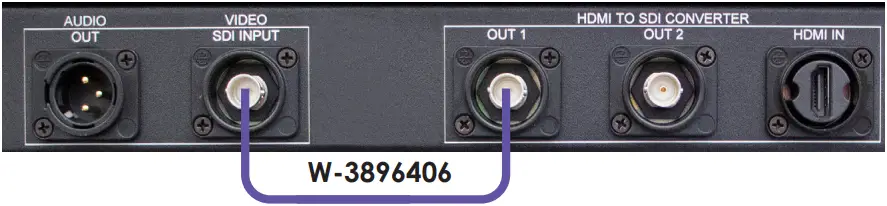
- HDMI: Connect to the HDMI IN jack on VPP #1, then connect the 15″ violet coaxial cable (part # W-3896406) between the OUT 1 jack and the SDI INPUT jack.
- Analog (Not Provided by Daktronics): If using an analog video signal, an analog-to-SDI converter will need to be sourced by the customer. Connect coaxial cable with BNC connectors between the SDI output jack on the converter and the SDI IN jack on VPP #1.
Note: The converter may have settings to adjust depending on the type of analog signal (component, composite, etc.) coming in. Refer to the documentation provided with the converter for proper input settings.
6. Plug power cords for all devices (portable control rack, Show Control laptop, monitors, etc.) into standard wall outlets.
7. After turning on the Show Control computer, ensure it is licensed. Refer to the Show Control Software Licensing Quick Guide (DD1785842), available online at www.daktronics.com/manuals.
Config Profiles
The system ships configured with a 720p output by default.
To change the output resolution to 1080p:
1. Open a web browser and go to http://192.168.0.237/#profiles to access the DMP-8000 Config Profiles window.
Note: If asked to enter login credentials, the defaults are Username: vnet and Password: dakpassv.
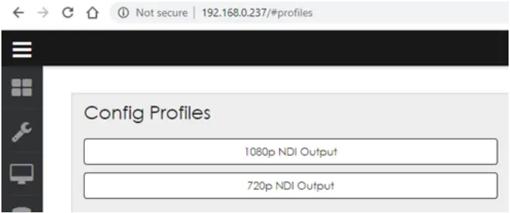
2. Select 1080p NDI Output.
3. Click Continue when the confirmation message opens.
4. Wait for the player to restart. A green check mark indicates when the process is completed.
Reusing Existing Content
In general, Daktronics recommends creating new content specifically for streaming using the correct output resolutions (720p = 720 x 1280 or 1080p = 1080 x 1920).
Depending on the size and aspect ratio of existing display content, it may be possible to reuse the files for streaming. Otherwise, the content may still need to be recreated. For example, if you have a small 132 x 176 display with a 4:3 aspect ratio, streaming its content will not only cause pixelation due to upscaling, it will also be stretched to fit the width, giving it more of a squished appearance:

- Before
132 x 176 (4:3) - After
720 x 1280 (16:9)
However, if you already have a display with a 16:9 aspect ratio, the content will better fit the aspect ratio of the streaming output. The content can still become pixelated, depending on how much it needs to upscale, but this can work if time or resources are limited before a scheduled event.
Optional TriCaster Mini Setup
Refer to the instructions below and DWG-4715862 to set up the optional TriCaster Mini switcher and replay system. For more information, also refer to the TriCaster User Guide (http://new.tk/Manual-TC1-V2).
1. Remove the TriCaster Mini, Launchpad Mini, mouse, keyboard, and power adapters from the travel case. Set up this equipment – and the TimeWarp device – within 25′ of the control rack.
2. Place one 22″ ViewSonic monitor at the Replay operator location and the other 22″ ViewSonic monitor at the TriCaster switcher operator location. Both monitors should be within 6′ of the TriCaster Mini.
3. Make the following connections to the TriCaster Mini:
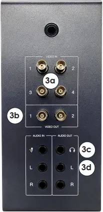
a. Connect BNC cables from up to four cameras to VIDEO IN 1-4.
b. Connect the 25′ BNC cable (part # W-1971) between a VIDEO OUT jack and the SDI INPUT jack on the rear of the rack.
c. Connect the 1/8″-to-1/4″ adapter into the 1/8″ TriCaster operator monitor audio cable, and then plug the adapter into the PHONES jack. The other end of the audio cable connects to the monitor’s AUDIO IN jack.
d. If there is an audio system, connect the 25′ 1/4″-to-XLR cable (part # W-4717001) between the AUDIO OUT L jack and an available input on the audio mixer.
e. Plug the supplied mouse, keyboard, TimeWarp, and Launchpad Mini devices into available USB ports.
f. Connect the 25′ network cable (part # W-4638308) between a NETWORK jack and an open jack on the network router in the control rack.
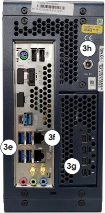
g. Connect one Mini-DisplayPort-to-DisplayPort adapter into one 6′ DisplayPort cable, and then plug the adapter into one of the Mini DisplayPort jacks. The other end of the cable connects to the 22″ Replay operator monitor. Repeat this to also connect the 22″ TriCaster operator monitor.
h. Connect the power adapter into the DC IN jack.
4. Plug power cords for all devices (TriCaster Mini, monitors, etc.) into standard wall outlets.
NDI Output to Streaming Device
This section describes an optional method of streaming the NDI output from the Big Stream DMP via a TriCaster. Other devices/ software may be used instead as long as they accept the NDI video source. If the streaming device does not accept NDI, the NDI output must be converted to a video input that the streaming device can accept using a converter such as the BirdDog NDI Encoder/Decoder.
Note: The streaming device must be connected into an open jack on the network router in the control rack.
In typical Daktronics video control systems, the TriCaster acts as a switcher for up to 4 video inputs. For the Big Stream system, the TriCaster Mini may also function as the streaming device. For more information about connections to the TriCaster, refer to Page 2.
Capturing the NDI Output
Each monitor on the TriCaster workspace can be configured to show any input or output. There are multiple virtual inputs that can be set to the NDI feed from the DMP.
1. Open the TriCaster program and start the desired session.
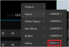
2. Right click an unused monitor, such as GFX1, and go to Inputs > INPUT 5.
3. Click the gear icon ![]() in the lower-right of the Input 5 monitor to open the input settings.
in the lower-right of the Input 5 monitor to open the input settings.
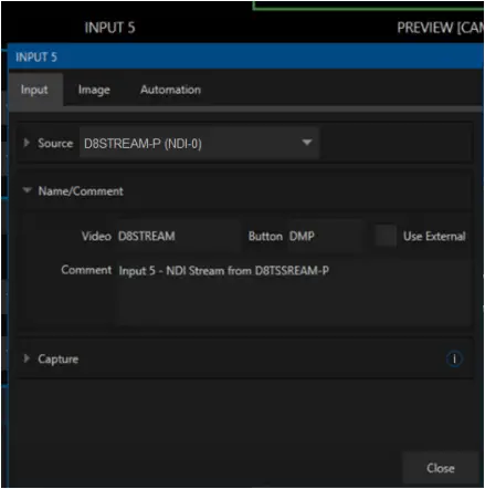
a. In the Source drop-down list, select D8STREAM-P and then NDI-0.
b. Expand the Name/Comment section. Rename Video to D8STREAM and Button to DMP, and add a descriptive Comment as desired.
c. Click Close when finished.
Note: If content is playing out of the DMP, it will appear in the D8STREAM monitor.
Streaming the NDI Output
1. Click the STREAM/ENCODE button at the top of the screen.
2. Click Source Setup.
MIX 1 is the primary output to the display*. Mix 4 is the replay mix.
MIX 2 will be used for the separate streaming mix.
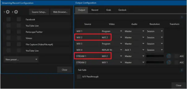
a. Change MIX 2 Video to M/E 2.
b. Change STREAM 1 Video to MIX 2.
c. Adjust the Audio output source if desired.
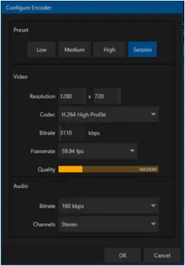
3. Click the STREAM 1 gear icon and adjust the encoder settings as desired. The default settings should work for most applications.
Click OK when finished.
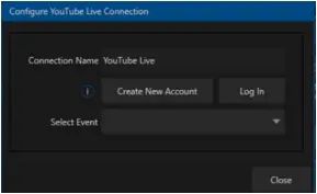
4. Check the streaming platform(s). Hover over and select the settings gear icon to log in to an account or adjust as needed.
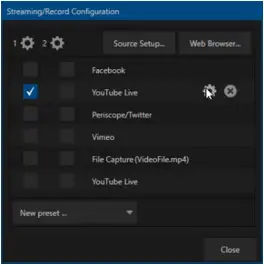
5. Close out of all settings windows when finished.
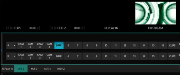
6. Back on the main interface, select DMP on the M/E 2 bar.
Selecting DMP on the M/E 2 bar will make it the active M/E 2 source. The active M/E 2 source is MIX 2, which is the configured streaming source.
TriCaster Registration
On first time start-up, the installer may assist in registering the TriCaster for the end user. This can be done very easily if an internet connection is available. If not, call NewTek Customer Service:
- (US) 1-800-862-7837
- (Outside US) +1-210-370-8452
Both the Serial Number (located on the TriCaster unit) and Product ID (presented during registration) are required to obtain the necessary Registration Code.
For more information about registration, operation, or troubleshooting of the TriCaster system, visit www.newtek.com/support/get-support.
For More Information
To learn more about the Daktronics Show Control System software, consult the Show Control System User Handbook:
- Press the Windows key [
 ] and go to All Programs > Daktronics > Display Studio > Show Control System User Handbook.
 - From within Display Studio, press the Display Studio Hub button and select Help.
Watch the following YouTube video for an introduction to Show Control: www.youtube.com/watch?v=3Q28olggTGo
For any other questions, comments, or concerns, please contact Daktronics Support Services:
United States & Canada
Toll Free: 1-800-DAKTRONICS (1-800-325-8766)
Outside the U.S. & Canada
+1-605-697-4000
Real-Time Data (Scoring & Timing)
This type of installation will often include an All Sport® 5000 series scoreboard control console, the All Sport Pro scoring system, and/or a statistics computer for displaying Real-Time Data (RTD).
- If the All Sport is located in the same room, it may be possible to run the cables directly to the network router without J-boxes.
- If the All Sport is in a separate location, install network J-boxes and run Cat5 cable.
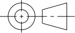
Refer to DWG-1053539 or DWG-4768575 for more information about connecting RTD sources into the display control network.
Note: For information on setting up real-time data for track timing, refer to the Track & Field Interfaces for Scoreboards & Displays Setup Guide (DD3059635), available online at www.daktronics.com/manuals.
![]()
DD4734683
Rev 02
25 July 2022
201 Daktronics Drive
Brookings, SD 57006-5128
www.daktronics.com/support
800.325.8766
RACK ROOM
CONTROL ROOM EQUIPMENT PROJECT SPECIFIC
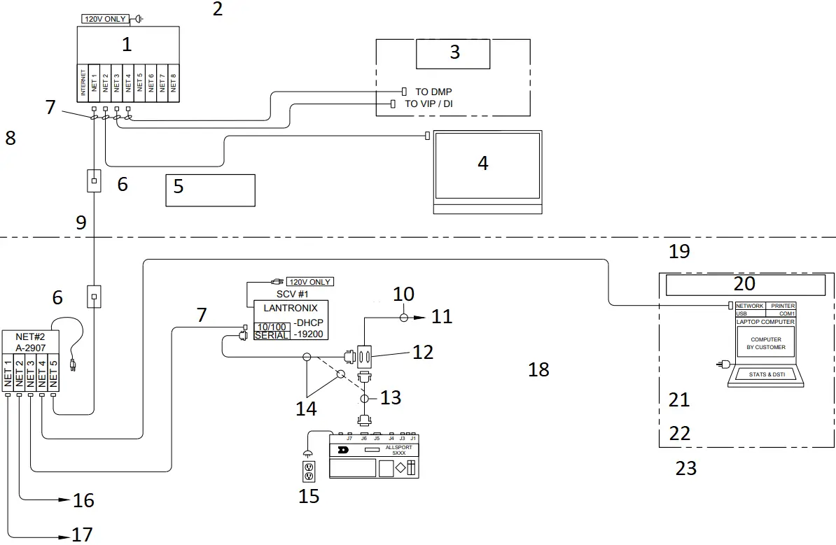
- ROUTER
(PART# MAY VARY) - *NOTE: SITE SPECIFIC RISER DIAGRAM(S) TAKE PRECEDENCE OVER THIS OR ANY OTHER STANDARD DRAWING.
- STANDARD VIDEO CONTROL OPTION
- SHOW CONTROL COMPUTER
- **NOTE**
CAT5E RUNS MUST BE LESS THAN 250′ - RJ45 J-BOX
0A-1177-1028
2″X4″ - W-1343 (14′)
0A-1177-1028
8-PIN RJ45
PIN#
WIRE COLOR 1 WHT/ORG
2
ORG 3 WHT/GRN
4
BLU 5 WHT/BLU
6
GRN 7 WHT/BRN
8
BRN
- W-1384
CAT5E - 22AWG SHIELDED PAIR COPPER CABLE
- TO FIBER CONVERTER CARD OR DIRECTLY TO SCOREBOARD
- JB1
0A-1166-0027
DUAL 25-P J-BOX, 2″X4″ - W-1247, 25′
- 0A-1453-0033, 10′
- (2) 15AMP
DUPLEX RECEPTACLE BY CUSTOMER - TO CUSTOMER STATCREW COMPUTER (IF APPLICABLE)
- ALTERNATE SHOW CONTROL CONNECTION LOCATION
JB1:J1 ALLSPORT J1 OUTPUT TABLE
PIN# OUTPUT # SIGNAL
14
1+ SCBD OUTPUT 15 1-
16
2+ GAME/SHOT CLOCK 17 2-
18
3+ LOCKER ROOM CLOCKS 19 3-
3
CL + VENUS RTD 7 GND
- ASSEMBLIES:
0A-1453-0115: KIT; STD VIDEO, A/S, RTD INPUT
0A-1453-0116: KIT; STD VIDEO, A/S, DAKSTATS RTD INPUT
0A-1453-0117: KIT; STD VIDEO, A/S, STATCREW RTD INPUT - EXPANDED STATS INTERFACE DETAIL:
- NOTE:
DAKSTATS STATISTICS PROGRAM AND THE DSTI INTERFACE PROGRAMS MAY BE PURCHASED FROM DAKTRONICS. - STAT CREW STATISTICS PROGRAM IS PROVIDED BY OTHERS.
JB1:J2 ALLSPORT J2 OUTPUT TABLE
PIN# OUTPUT # SIGNAL
2
RX RS-232 RTD 3 TX
7
GND
REV | DATE: | UPDATED DVXMC TO STANDARD VIDEO CONTROL | BY: | |
REV | DATE: | CHANGED VERTICAL A BORDER TO HORIZONTAL | BY: | |
REV | DATE: | ADDED DESCRIPTION BOX FOR ALL SPORT INTERFACE UPDATED DMP AND VIP LABELS | BY: | |
REV | DATE: | CORRECTED SPELLING ERRORS UPDATED DMP AND VIP LABELS | BY: | |
REV | DATE: | UPDATED LANTRONICS VIEW ADDED A-2907 DETAIL | BY: | |
REV | DATE: | UPDATED TITLE | BY: |
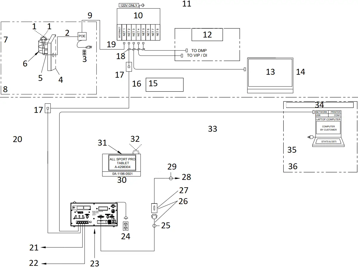
| THIRD ANGLE PROJECTION
| ||||
| PROJ: STANDARD VIDEO | |||||
| TITLE: RISER; STANDARD VIDEO, RTD, BASIC & EXTENDED STATS | |||||
| DESIGN: SBRINK | DRAWN: SBRINK | DATE: 16 MAY 11 | |||
| SCALE: NONE | |||||
SHEET | REV | JOB NO: | FUNC SIZE | 1053539 | |
06 | P1453 | F – 03 – A | |||
Part # – DWG-01053539 Version – 06.2 Description – N A RISER; STD VID, RTD, BASIC & EXTENDED STATS Lifecycle State – Full Production Last Modified By – ibrandt Last Modified – 2020-11-16
RACK ROOM
CONTROL ROOM EQUIPMENT PROJECT SPECIFIC
- 0A-2125-7300: WIRELESS CLIENT TO ALL SPORT PRO TABLET
- RJ45
W-2227
(100FT) - (1) 15AMP
DUPLEX RECEPTACLE BY CUSTOMER - RACK ROOM WALL
- MOUNTING PLATE, WALL OR POLE MOUNT
- ADD EN-1847 PROTECTIVE SCREEN COVER FOR ALL INDOOR INSTALLATIONS
- 0A-2125-7000
WIRELESS AP KIT REQUIRED WHEN USING THE ALL SPORT PRO IPAD - IN LINE OF SIGHT WITH COURT SIDE TABLE
- SUPPLIED WITH POE
- ROUTER (PART# MAY VARY)
- *NOTE: SITE SPECIFIC RISER DIAGRAM(S) TAKE PRECEDENCE OVER THIS OR ANY OTHER STANDARD DRAWING.
- STANDARD VIDEO CONTROL OPTION
- SHOW CONTROL COMPUTER
- ALL SPORT PRO SOFTWARE INSTALLED ON SCS COMPUTER
- **NOTE**
CAT5E RUNS MUST BE LESS THAN 250′ - W-1384
CAT5E - RJ45 J-BOX
0A-1177-1028
2″X4″ - W-1343 (14′)
- W-1542
0A-1177-1028
8-PIN RJ45
PIN#
WIRE COLOR 1 WHT/ORG
2
ORG 3 WHT/GRN
4
BLU 5 WHT/BLU
6
GRN 7 WHT/BRN
8
BRN
- TO CUSTOMER STATCREW COMPUTER (IF APPLICABLE)
- ALTERNATE SHOW CONTROL CONNECTION LOCATION
- 0A-1196-0511: ALL SPORT PRO INTERFACE KIT
- (2) 15AMP
DUPLEX RECEPTACLE BY CUSTOMER - W-1247, 25′
- IF APPLICABLE
- JB1
0A-1065-0056
25-P J-BOX, 2″X4″ - TO FIBER CONVERTER CARD OR DIRECTLY TO SCOREBOARD
- 22AWG SHIELDED PAIR COPPER CABLE
- FRONT VIEW ALL SPORT PRO INTERFACE
- INSTALLER NOTE:
CLEAR LINE OF SIGHT RECOMMENDED BETWEEN ACCESS POINT AND TABLET - LINE OF SIGHT RADIO COMMUNICATIONS TO LOCAL WIRELESS SCORING SYSTEM, IF EQUIPPED
JB1:J1 ALLSPORT J1 OUTPUT TABLE
PIN# OUTPUT # SIGNAL
14
1+ SCBD OUTPUT 15 1-
16
2+ GAME/SHOT CLOCK 17 2-
18
3+ LOCKER ROOM CLOCKS 19 3-
3
CL + VENUS RTD 7 GND
- EXPANDED STATS INTERFACE DETAIL:
- NOTE:
DAKSTATS STATISTICS PROGRAM AND THE DSTI INTERFACE PROGRAMS MAY BE PURCHASED FROM DAKTRONICS. - STAT CREW STATISTICS PROGRAM IS PROVIDED BY OTHERS.
REV | DATE: 2 JUN 21 | ADDED NOTE ABOUT PROTECTIVE COVER EN-1847 | BY: MTR | |
| REV 01 | DATE: 16 NOV 20 | UPDATED SIZE OF DWG | BY: |
| THIRD ANGLE PROJECTION
| |||
| PROJECT: STANDARD VIDEO | ||||
| TITLE: RISER; STANDARD VIDEO, ALL SPORT PRO, STATS | ||||
| DATE: 06 NOV 20 | DIM UNITS: INCHES [MILLIMETERS] | SHEET | REV | |
| SCALE: NONE | DO NOT SCALE DRAWING | |||
| DESIGN: HBONER | JOB NO. P1920 | FUNC – TYPE – SIZE | 4768575 | |
| DRAWN: IBRANDT | ||||
***NOTE: SITE SPECIFIC RISER DIAGRAM(S) TAKE PRECEDENCE OVER THIS OR ANY OTHER STANDARD DRAWING.
TRICASTER EXTENSION KIT EQUIPMENT LIST | ||
| PART DESCRIPTION | PART NUMBER | QUANTITY |
22″ MONITORS | A-2430 | 2 |
| TIME WARP 850TW REPLAY CONTROLLER | A-3343 | 1 |
LAUNCHPAD MINI MK3 | A-3450 | 1 |
| TRICASTER MINI ADVANCED SDI | A-4715564 | 1 |
TRICASTER MINI TRAVEL CASE | EN-4715565 | 1 |
| 25′ BNC VIDEO CABLE | W-1971 | 1 |
ADAPTER; 1/4″ PLUG TO 1/8″ JACK | W-2494 | 1 |
| 6′ DISPLAYPORT CABLE | W-3271379 | 2 |
6FT 1/8″ TO 1/8″ STEREO CABLE | W-3511512 | 1 |
| 25FT CAT5E NETWORK CABLE | W-4638308 | 1 |
25FT 1/4″ TRS PLUG TO XLR M CABLE | W-4717001 | 2 |
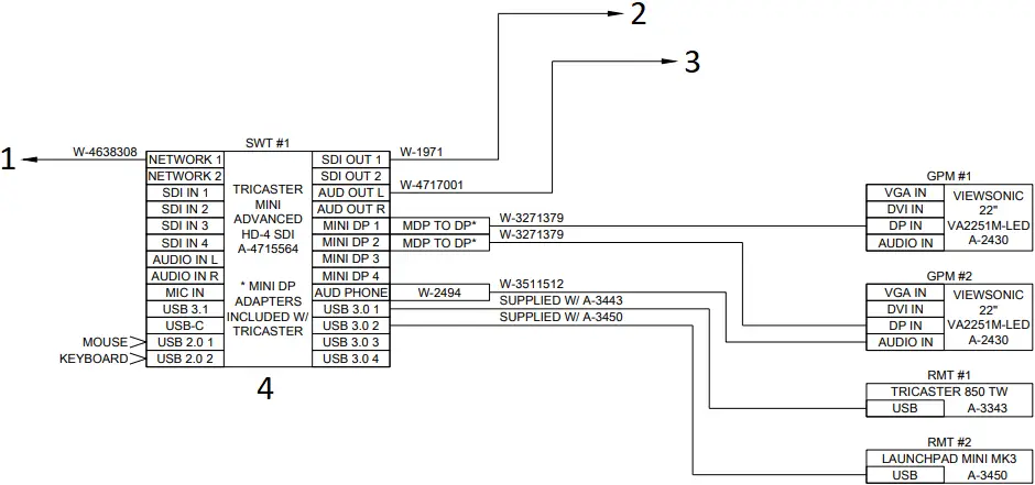
- TO NETWORK ROUTER
- TO DMP-8221 SDI INPUT
- TO CONSUMER AUDIO SYSTEM
- ***NOTE: THE TRICASTER MINI AND ITS ACCESSORIES ARE STORED IN A TRAVEL CASE
INSTALLATION NOTES:
- REMOVE TRICASTER, MOUSE, KEYBOARD, AND POWER ADAPTER FROM THE TRAVEL CASE.
- SET UP EQUIPMENT ON COUNTER WITHIN 25′ OF VIDEO RACK.
- CONNECT (2) MINI DISPLAYPORT TO DISPLAYPORT VIDEO ADAPTERS TO THE TRICASTER.
- CONNECT THE TWO MONITORS WITH THE INCLUDED DISPLAYPORT CABLES.
- SET THE CONTROLLERS NEAR ONE OF THE MONITORS AND CONNECT THE USB TO THE TRICASTER.
- CONNECT THE INCLUDED NETWORK CABLE BETWEEN THE TRICASTER AND SITE NETWORK ROUTER.
- CONNECT THE INCLUDED BNC VIDEO CABLE BETWEEN THE TRICASTER AND THE DMP IN THE VIDEO RACK.
- REFER TO BIG STREAM QUICK GUIDE FOR SETUP AND OPERATION.
| THIRD ANGLE PROJECTION
| |||
| PROJECT: SPORTS VIDEO SYSTEMS | ||||
| TITLE: SPORTS VIDEO SYSTEMS KIT; TRICASTER MINI ADVANCED SDI W/ TRAVEL CASE | ||||
| DATE: 28 JULY 20 | DIM UNITS: INCHES [MILLIMETERS] | SHEET | REV | |
| SCALE: NONE | DO NOT SCALE DRAWING | |||
| DESIGN: TKELLEY | JOB NO. P1453 | FUNC – TYPE – SIZE | 4715862 | |
| DRAWN: TKELLEY | ||||
Part # – DWG-04715862 Version – 00.1 Description – N B KIT; TRICASTER MINI ADV SDI W/ TRAVEL CASE Lifecycle State – Full Production Last Modified By – tkelley Last Modified – 2020-08-21
This page intentionally left blank.
ADDITIONAL EQUIPMENT
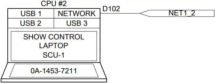
*** NOTE: THE LAPTOP IS LOCATED ON THE TOP COMPARTMENT OF THE PORTABLE CASE. AN OPTIONAL 100′ NETWORK CABLE IS INCLUDED TO ALLOW LAPTOP TO BE SET UP AWAY FROM THE PORTABLE CASE.
***NOTE: ALL EQUIPMENT IS RACKMOUNTED UNLESS OTHERWISE NOTED
***NOTE: SITE SPECIFIC RISER DIAGRAM(S) TAKE PRECEDENCE OVER THIS OR ANY OTHER STANDARD DRAWING.
***NOTE: SECURE TO RACK SHELF USING AT-1059
- ***NOTE: SECURE TO SHELF USING AT-1059
- ***NOTE: SECURE TO RACK SHELF USING AT-1059
***NOTES:
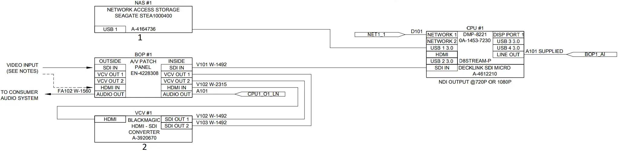
- FOR OPTIONAL HDMI INPUT; CONNECT W-3896406 (PATCH CABLE) BETWEEN ‘OUTPUT 1’ AND ‘SDI IN.’ REFER TO FIGURE 1.
- FOR SDI INPUT; DISCONNECT THE W-3896406 (PATCH CABLE) FROM ‘SDI IN’ AND CONNECT THE SOURCE DIRECTLY TO ‘SDI IN.’
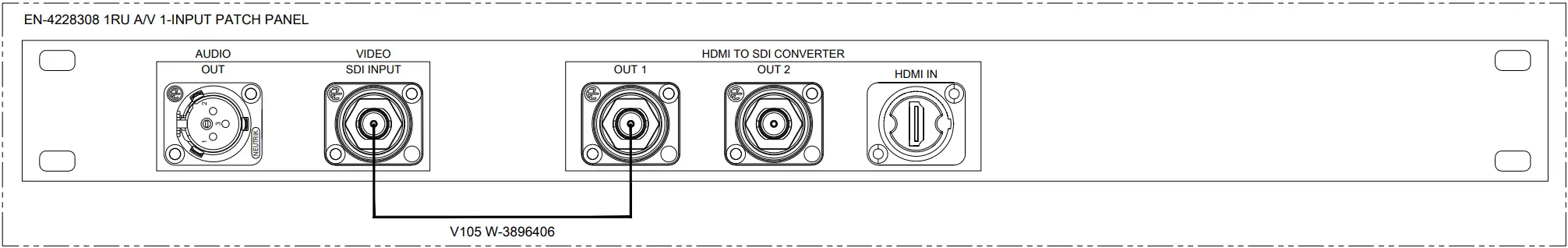
FIGURE 1
CABLE LABELS: DD4696055
EQUIPMENT LABELS: DD4696059
REV | DATE: | CHANGED NETWORK ROUTER PER CN-143352. | BY: |
| THIRD ANGLE PROJECTION
| |||
| PROJECT: SPORTS VIDEO SYSTEMS | ||||
| TITLE: CONTROL; SCHEMATIC – 1-INPUT STREAMING KIT | ||||
| DATE: 11 JUN 20 | DIM UNITS: INCHES [MILLIMETERS] | SHEET | REV | |
| SCALE: NONE | DO NOT SCALE DRAWING | |||
| DESIGN: TKELLEY | JOB NO. P1453 | FUNC – TYPE – SIZE | 4694089 | |
| DRAWN: TKELLEY | ||||
Part # – DWG-04694089 Version – 01.2 Description – N D CONTROL; SCHEMATIC- SVS 1-INPUT NDI STREAMING Lifecycle State – Full Production Last Modified By – tkelley Last Modified – 2022-07-15
EQUIPMENT LIST | ||
| PART DESCRIPTION | PART NUMBER | QUANTITY |
4RU PORTABLE SKB CASE | EN-4115582 | 1 |
| RACK SCREWS | HC-1522 | 28 |
CABLE TIE; 8″ | HE-1275 | 20 |
| VELCRO STRAP | HE-1474 | 1 |
1RU UTILITY SHELF | EN-1896 | 1 |
| 1RU RACK SHELF FOR CPUS & DIPS | EN-2842 | 1 |
CABLE LABEL | LL-2416 | AS NEEDED |
| EQUIPMENT LABEL (BLACK) | LL-2658 | 6 |
VELCRO, CLR 1″ DUAL LOCK | AT-1059 | 40 |
- FRONT VIEW
- REAR VIEW
(W/ COVER) - DISCONNECT PATCH CABLE FROM BOP #1 IF USING AN HD/SD-SDI VIDEO SOURCE
HEAT LOAD (BTU/HR) | POWER LOAD (WATTS) | WEIGHT (LBS) | WEIGHT (KGS) | |
| RACK TOTAL | 248 | 73 | 42 | 19 |
1 – 20 AMP 120 VAC CIRCUIT
TOP VIEW

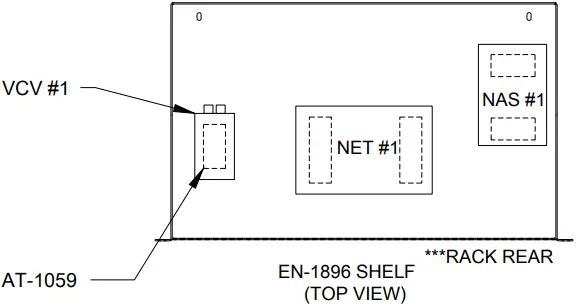
NOTE:
- SECURE COMPONENTS TO EN-1896 SHELF USING AT-1059.
REV | DATE: | CHANGED NETWORK ROUTER PER CN-143352. | BY: | |
REV | DATE: | UPDATED COMPONENT LAYOUT PER CN-108005. | BY: |
| THIRD ANGLE PROJECTION
| |||
| PROJECT: SPORTS VIDEO SYSTEMS | ||||
| TITLE: CONTROL; RACK ELEVATION – 8HU 1-INPUT STREAMING KIT | ||||
| DATE: 11 JUN 20 | DIM UNITS: INCHES [MILLIMETERS] | SHEET | REV | |
| SCALE: 1=4 | DO NOT SCALE DRAWING | |||
| DESIGN: TKELLEY | JOB NO. P1453 | FUNC – TYPE – SIZE | 4694090 | |
| DRAWN: TKELLEY | ||||
Part # – DWG-04694090 Version – 02.2 Description – N D CONTROL; RACK ELEV – 4RU 1-INPUT NDI STREAMING Lifecycle State – Full Production Last Modified By – tkelley Last Modified – 2022-07-15


