YAMATIC 3000 PSI 7/8 Inch Shaft Vertical Pressure Washer Pump
Product Information
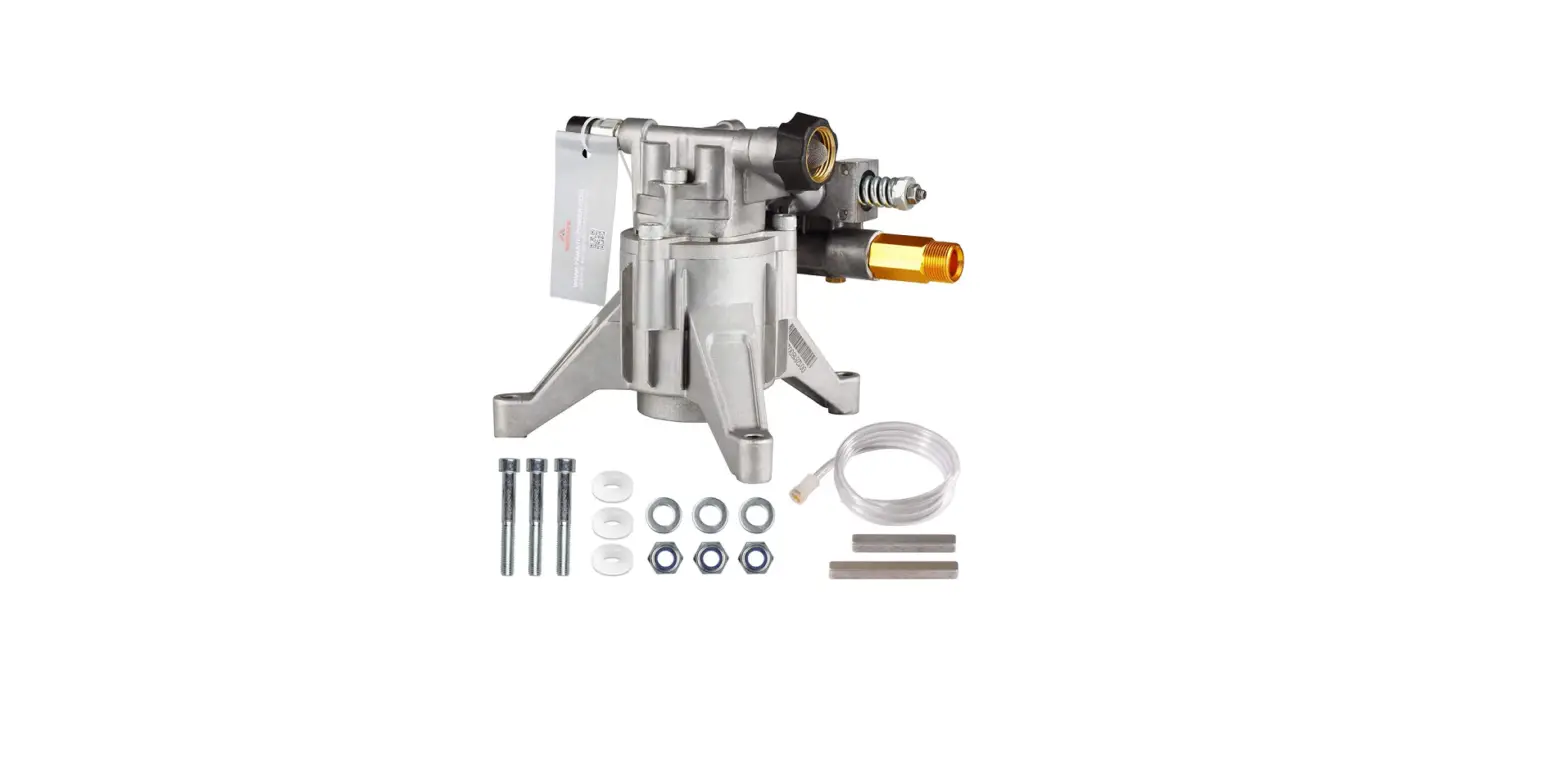
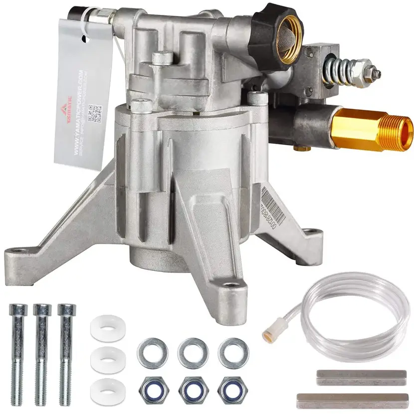
YAMATIC OEM Pressure Washer Pump
- The YAMATIC OEM Pressure Washer Pump is an axial pump made of aluminum alloy. It has a manifold crankcase and double-bearing lubrication. The pump is pre-sealed with 85W90 oil and has a self-suction inlet connector of a 3/4” NH garden hose. The outlet connector is M22x1.5-14mm. The pump is designed to pump non-flammable or non-explosive fluids and is intended to pump clean filtered water only.
- The pump should not be operated in or around an explosive environment. It is important to wear safety glasses or goggles and appropriate clothing while operating the pump. The pump should not be operated by children and the high-pressure discharge should never be pointed at a person, any part of the body or animals. Gasoline engines should not be operated in a confined area and adequate ventilation should always be ensured.
- The pump specifications of speed or pressure should not be exceeded and the pump should not be altered from the manufacturer’s design.
Product Usage Instructions
INSTALLATION OF DIRECT DRIVE PUMPS
- Install the shaft key into the keyway and apply a light coating of anti-seize on the engine shaft.
- Align the two keyways and push the pump completely onto the engine.
- Install all bolts and tighten them evenly.
- Remove the protection cap of the outlet and unloader the valve.
- Install the appropriate water inlet fitting (3/4-11.5 NH).
- Connect the water supply hose and outlet (M22x1.5-14 Hose or adapter) and high-pressure discharge hose/spray gun.
- Turn on the water supply.
- Open the spray gun to purge the system of any air.
- Start the engine.
- Adjust the engine speed at rated 3,400 RPM will get the best performance.
- Open the gun trigger to check if the pump is working well and if the installation and connection are all good.
It is important to note that the instructions in the manual should be read and saved before attempting to assemble, install, operate, or maintain the product. All safety information should be observed and failure to comply with instructions could result in personal injury and/or property damage. The water supply should be clean and free of debris that can cause excess pump wear and reduce performance. An insufficient water supply can damage the pump, so ensure that the water supply is steady and is 20% over the rated flow of the pump. The water supply garden hose must have an inside diameter of at least 5/8. If the hose is more than 100 ft. long, the diameter must be at least 3/4.
TECHNICAL SPECIFICATION
- Type: Axial
- Manifold: Aluminum Alloy
- Crankcase: Aluminum Alloy
- Bearing: Double Bearing
- Lubrication: 85W90 Pre-Sealed
- Self-suction: NO
- Inlet Connector: 3/4” NH Garden Hose
- Outlet Connector: M22x1.5-14mm
GENERAL SAFETY INFORMATION
![]()
- The pump is designed to pump non-flammable or non-explosive fluids.
- These pumps are intended to pump clean filtered water only.
- Do not operate in or around an explosive environment.
- Always wear safety glasses or goggles and appropriate clothing.
- Do not allow children to operate the pump.
- Never point the high-pressure discharge at a person, any part of the body, or animals.
- Do not operate gasoline engines in a confined area and always have adequate ventilation.
- Do not exceed the pump specifications in speed or pressure.
- Do not alter the pump from the manufacturer’s design.
NOTE:
Please read and save these instructions. Read carefully before attempting to assemble, install, operate or maintain the product described. Protect yourself and others by observing all safety information. Failure to comply with instructions could result in personal injury and/or property damage! Retain instructions for future reference.
Assembly drawing for HORIZONTAL Pump
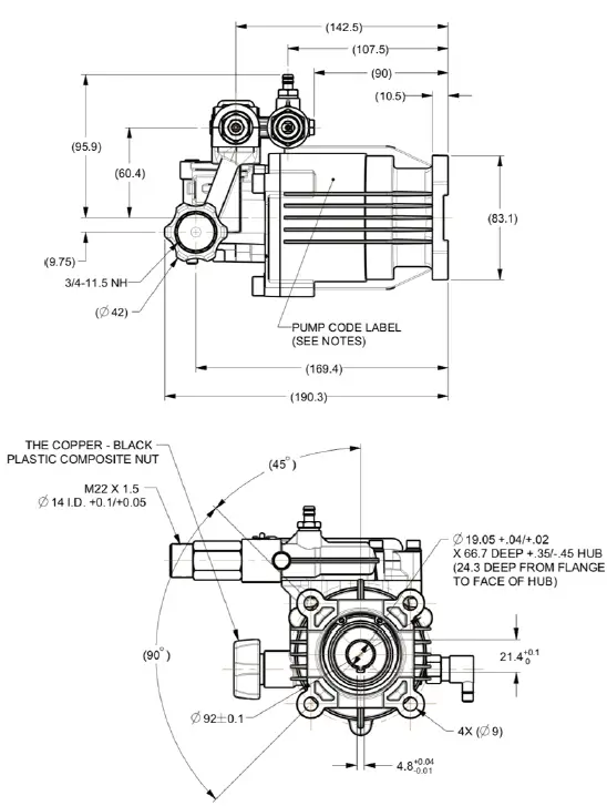
Assembly drawing for REAR SIDE INLET VERTICAL Pump
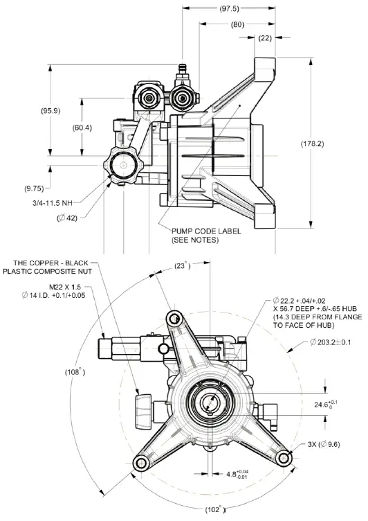
Assembly drawing for FRONT SIDE INLET VERTICAL Pump
NOTE:
If the inlet/outlet is blocked by the front frame cover, please modify or remove the front frame cover to provide good clearance for the high-pressure outlet connection.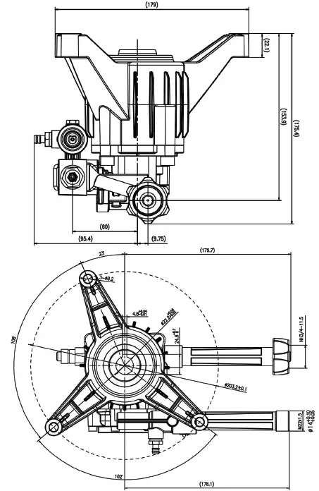
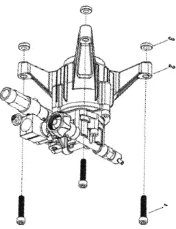
Washer Bolt forVERTICAL Pump
- Blot
- Blot hole
- Washer
TIPS:
- When your engine shaft length is longer from the engine flange (PTO) to the shaft end, when you set up the engine shaft and pump, you will find the gap between the pump boss and the engine bottom or flange.
- Then you need to put the washer into the gap, between your original engine flange and pump boss, then screw up the bolt for some engines, need washers for all three pump bosses.

OPERATION TIPS
Water Supply:
- Make sure the water supply is clean. Debris can cause excess pump wear and reduce performance.
- An insufficient water supply will damage your pump. Make sure the water supply is steady and is 20% over the rated flow of your pump. Use a stopwatch to time how long it takes to fill a 5-gallon bucket with your garden hose.
- The water supply garden hose must have an inside diameter of at least 5/8”. If the hose is more than 100 ft. long, the diameter must be at least 3/4”.
- Never use a reservoir tank as a water source. Drawing water out of a tank may cause pump cavitation and damage to your pump. This pressure washer is designed for a pressurized water source such as a city water faucet. However, the water source pressure must not exceed 115 psi (8 bar). Always use a flexible rubber hose for your water supply. Do not use rigid piping.
TROUBLESHOOTING GUIDE
| Symptom | Possible Cause(s) | Corrective Action |
|
Low Pressure | Worn nozzle | Replace nozzle, of proper size |
| Belt slippage | Tighten or replace; use correct belt | |
| Air leak in inlet plumbing | Disassemble, reseal and reassemble | |
| Relief valve studk, partially plugged or improperly adjusted valve seat worn | Clean, adjust relief valve; check for worn and dirty valve seats. Kit available | |
| Inlet suction strainer clogged or improperly sized | Clean. Use adequate size. Check more frequently | |
| Worn packing. Abrasives in pumped fluid or severe cavitation. Inadequate water | Install proper filter. Suction at inlet manifold must be limited to lifting less than 20 feet of water or -8.5 PSI vacuum | |
| Fouled or dirty inlet or discharge valves | Clean inlet and discharge valve assemblies | |
| Worn inlet, discharge valve block or dirty | Replace worn valves, valve seats and/or discharge hose | |
| Leaky discharge hose | ||
| Oil leak between crankcase and pumping section | Worn rod oil seals | Replace crankcase piston rod seals |
| Frequent or premature failure of the packing | Cracked, damaged or worn plunger | Replace plungers |
| Overpressure to inlet manifold | Reduce inlet pressure | |
| The material in the fluid being pumped | Install proper filtration on the pump inlet plumbing | |
| Excessive pressure and/or temperature of the fluid being pumped | Check pressures and fluid inlet temperature; be sure they are within the specified range | |
| Running pump dry | Do not run pump without water | |
| Pump runs but produces no flow | Pump is not primed | Flood suction then restart pump |
| Pump fails to prime | Air is trapped inside pump | Disconnect discharge hose from pump. Flood suction hose, restart pump and run pump until all air has been evacuated |
| Pump looses prime, chattering noise, pressure fluctuates | Air leak in suction hose or inlet | Remove suction line and inspect it for a loose liner or debris lodged in hose. Avoid all unnecessary bends. Do not kink hose |
| Clogged suction strainer | Clean strainer | |
|
Low pressure at nozzle | Unloader valve is by-passing | Make sure unloader is adjusted property and by-pass seat is not leaking |
| Incorrect or worn nozzle | Make sure nozzle is matched to the flow and pressure of the pump. If the nozzle is worn, replace | |
| Worn packing or valves | Replace packing or valves | |
| Pressure gauge fluctuates | Valves worn or blocked by foreign bodies | Clean or replace valves |
| Packing worn | Replace packing | |
| Pump runs extremely rough, pressure very low | Inlet restrictions and/or air leaks. | Clean out foreign material |
| Stuck inlet or discharge valve | Replace worn valves | |
| Slight leak, oil leaking in the area of crankshaft | Worn crankshaft seal or improperly installed oil seal o-ring | Remove oil seal retainer and replace damaged 0-ring and/or seals |
| Bad bearing | Replace bearing | |
| Water leakage from under manifold | Worn packing or cracked plunger | Install new packing or plunger |
| Excessive play in the end of the crankshaft pulley | Worn main bearing from excessive tension on drive belt | Replace crankcase bearing and/or tension drive belt |
| Water in crankcase | Humid air condensing into water inside the crankcase | Change oil intervals |
| Worn packing and/or cracked plunger | Replace packing. Replace plunger | |
| Loud knocking noise in pump | Cavitation or sucking air | Check water supply is turned on |
| Pulley loose on crankshaft | Check key and tighten set screw | |
| Broken or worn bearing | Replace bearing |


