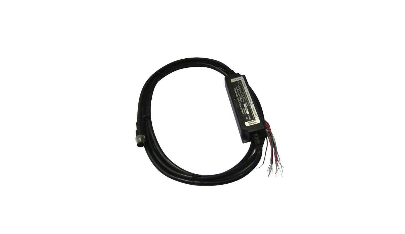
FURUNO NMEA 2000 Analog Data Converter Installation Guide
NMEA 2000 GENERAL OVERVIEW
Key Points;
- Network Power: 9-16V, isolated from other circuits.
- Maximum Backbone Length: 100m with micro/mini(light) / 200m with mid(heavy) cable
- Maximum Number of Devices per Backbone, 50 ea.
- Maximum Drop Length per Drop, 6m.
- Maximum Total Drop length per Backbone, 78m.
- Maximum Power Capacity per Segment, 3A with light / 8A with heavy cable.

BASIC NETWORK COMPONENTS
NMEA2000 networks need to consist of NMEA 2000 certified devices, approved teeconnectors, and cables. FURUNO USA supplies NMEA approved components as follows.
Starter Kit
NMEA2000 Starter Kit | |||
| Consists of | NMEA2000 Drop Cable, 2m | 1 ea. | 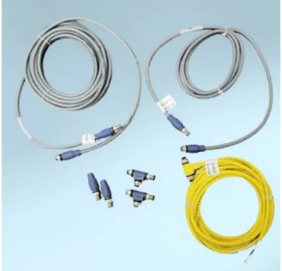 |
| NMEA2000 Backbone Cable, 6m | 1 ea. | ||
| NMEA2000 Power Tee, Micro F/F, 8m | 1 ea. | ||
| NMEA2000 Tee-Connector, Micro F/F/M | 2 ea. | ||
| NMEA2000 Micro Terminator, Micro Male | 2 ea. | ||
| Part Number | AIR-033-745 | ||
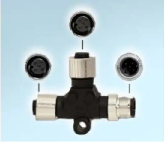
Connectors and Terminators
| Name | NMEA2000 Tee Connector | NMEA2000 Micro Terminator | NMEA2000 Micro Terminator |
 | 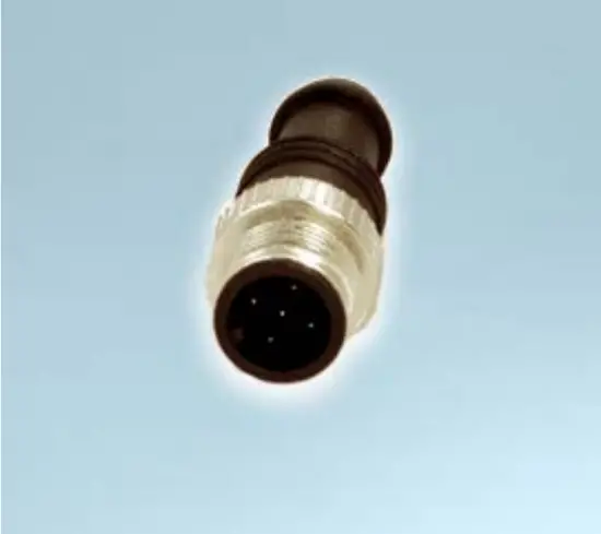 | 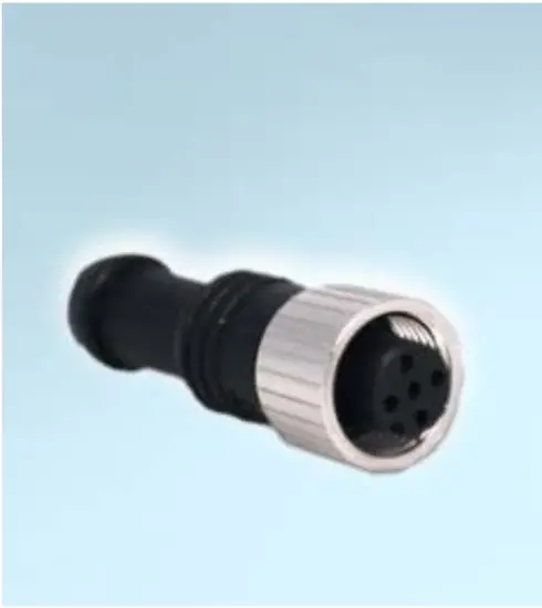 | |
| Conn. Type | Micro Female/Female/Male | Micro Male | Micro Female |
| P/N | AIR-052-531 | AIR-335-791 | AIR-335-792 |
Cables
| Name | NMEA2000 Micro Cable | NMEA2000 Micro Cable (Angled) | NMEA2000 Powr Tee | |||
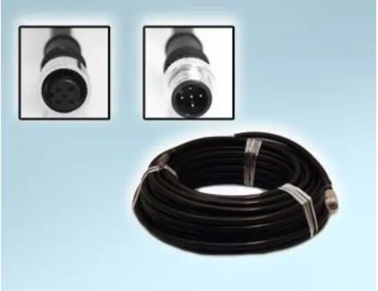 |
| 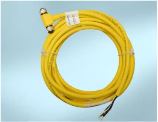 | ||||
| Conn. Type | Micro Male/Female | Micro Male/ Female, Angled | Micro Female/ Female | |||
| P/N | 1 meter | 001-533-060-00 | 1 meter | 001-105-830-10 | 8 meters | AIR-335 792 |
| 2 meters | 001-533-070-00 | 5 meters | 001-105-840-10 | |||
| 6 meters | 001-533-080-00 | 10 meters | 001-105-850 | |||
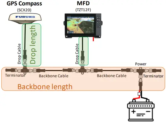
NETWORK DESIGNING
Network Power Source and Connection Type
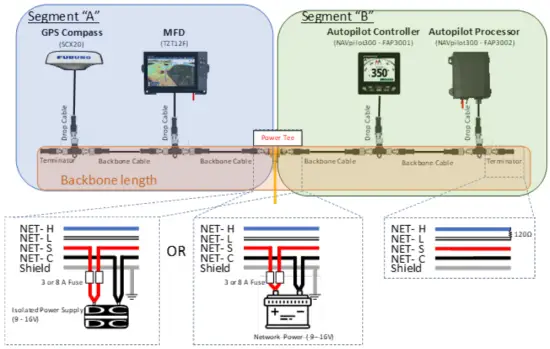
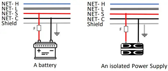
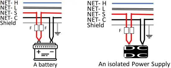
The NMEA 2000 network is designed to be electrically isolated from other circuits to prevent radio interference, so a dedicated network power source is required. The range should be 9 -16V. The network power source should be either single-point connection of a battery or one or more isolated power supplies distributed along the network, but it should not be a combination of battery and power supply connections, and each power line should have its own fuse. There are several power-connection types, and you can choose the one best suited for your system.
- Single Leg Backbone Power Connection
Simplest and most common method, and most boats can be utilize this method.
- Double Leg Backbone Power Connection
The double leg method will help to increase total power capacity per network by separating segments, but a NMEA 2000 dedicated power Tee or power isolator is required. Both power legs should connect to an isolated power supply or a battery.
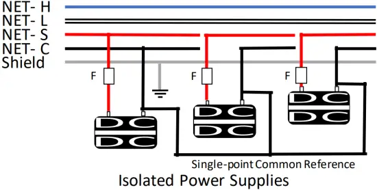
- Multiple Leg Backbone Power Connection
Multiple Legs may be required for vessels requiring a larger network. This method can be used with isolated power supplies only. Each power leg should be isolated from others, and a single-point common reference is necessary to avoid ground loops and to maintain control of ground-voltage levels between nodes.
Estimated Voltage Drop and Effective Backbone Length
Maximum Backbone length is defined by the standard but, Voltage Drop is always an important factor for actual network plaining in electrical world, without exception. The voltage drop can be calculated from the following formula, and it will determine the effective Backbone length for your system. The network diagram describing Load Equivalent Number (LEN) per device and cable lengths will be required to calculate the voltage drop.
VD = 0.1 x NL x BL x Cable Resistance
- VD = Voltage Drop (V)
- NL = total Network Len
- BL = Backbone Length (m)
- Cable Resistance = 0.0057Ω/m for light cable
The voltage drop should be less than 1.5V for 12V power networks. This is the nominal value of a 12V battery. Or less than 3.0V for 13.8V power which is typical power voltage from an isolated power supply.
A simplified graph indicating effective Backbone length vs Total LEN is shown below. (Orange area is overlapped on the Blue area.) If the cable length of your system is positioned in the masked area in the graph (based on your power source), the length should be fine. This method should not be applied to multiple power supply network, and you might need to use the detailed diagnosis method defined by NMEA 2000 standard.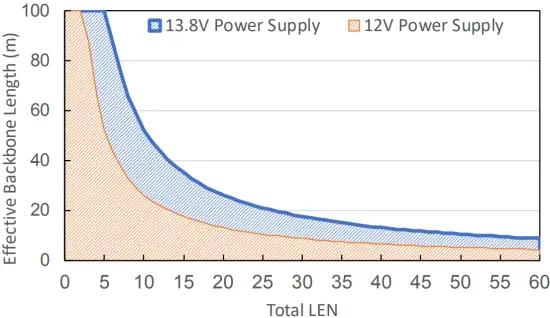
Drop Cable Length
The Drop Cable is a cable between the backbone and a device, and each cable length should not exceed 6 meters for stable communication. Additionally, the Total Drop Length per backbone should be under 78 meters.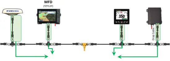
Gender Distinction of connector
Commonly female connectors are placed at the power supply side and male connectors are used at the power consuming side to prevent inadvertent touching of live conductors in the electronics world. You can always find a male connector on FURUNO NMEA 2000 device. NMEA 2000 Tee connector is designed to have devices connect to the center Female connector, and female and male connector at the sides should be used as backbone.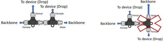
Termination Resistor
NMEA 2000 networks should have Two 120 Ω terminators, one at each end of Backbone to prevent signal reflections. One male and female terminator needs to be prepared with single power insertion network, and two male terminators will be required for the network using NMEA 2000 dedicated power tap cable. Total resistance of the finished network should read ~60 Ω.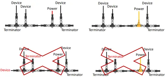
Shielding
The NMEA 2000 network is designed to be isolated from other circuits, so the shield cable is not bonded to device chassis. NMEA 2000 shielding should be continuous throughout the network and be connected to RF ground at One Single Point.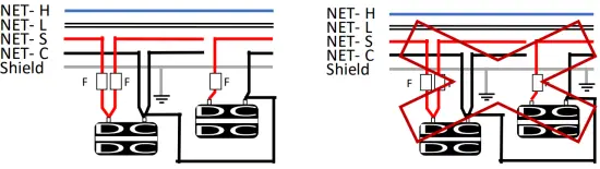
FIELD PROGRAMMING (INSTANCE SETUP)
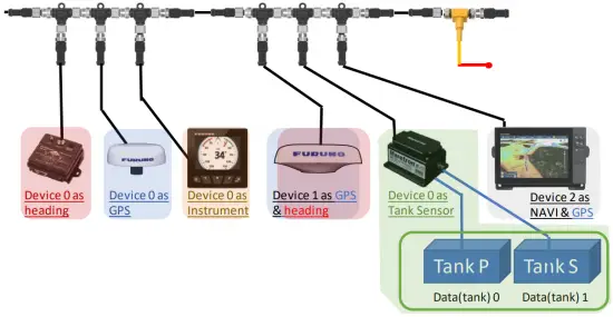
What is Instance?
NMEA 2000 devices are designed to have customizable fields for onsite grouping/identification of the data from duplicated and/or similar devices on the same network. So the first thing you do after installing NMEA 2000 devices is instancing as follows:
- Device Instance
Device instance needs to be assigned manually to NMEA 2000 devices to identify the data from duplicated and/or similar devices on the same network. Proper instancing to devices is the most important step for a stable network. Each device which can output the same PGN (data) in the network must be assigned a unique instance. (0 to 255). - Data instance
Data instance is designed to identify multiple PGNs carrying the same data from different sources transmitted by one device, like an engine gateway or a tank sensor connected to multiple level sensors. The valid range varies per PGN, and the configuration method depends on the gateway or sensor being used.
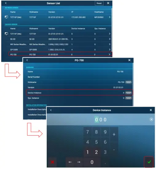
- Home-> Settings-> Initial Setup-> Sensor List
- Open “Sensor List”, found under Initial Setup
- Select the product
- Tap on Device Instance of sensor, then a keypad appears.
- Enter the device instance to ensure there is no conflict with other devices which output the same PGNs.
- Some devices require a power cycle to apply the change.

NavNet TZTouch2/Touch3 has ability to configure data instance for applicable FURUNO NMEA 2000 devices, i.e. IF-NMEAFI as of right now. This menu is available when using IFNMEAFI software version 1.02 or later.
- Connect an IF-NMEAFI to MFD via NMEA 2000
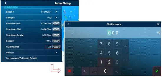
- Home-> Setting-> Initial Setup IF-NMEAFI Setup
- Select an IF-NMEAFI under “Select IF” menu found in “Initial Setup” on MFD. Please make sure to connect only one IF unit If you have two or more on the boat.
- Tap a keyboard icon at “Fluid Instance”, then keypad appears.
- Enter the fluid instance (0 – 14) to not conflict with other Tank sensor devices.

GENERAL INFORMATION AND REQUIRED PGNS
Multi-Function Displays and Remote displays can use NMEA2000 sensors as a direct source or calculation source for on-screen information. This following table explains general information and required PGNs. Note that the product must have the receiving capabilities for the PGN and that this is varied per product. Please refer to the operation manual to see the detailed PGN list.
| Information | Required PGNs for MFDs (PGNs for Instrument displays) | Notes | |
| Navigation Data | |||
| Data/Time | 126992 or 129033 | ||
| COG – Course Over Ground | 129026 or 130577 | ||
| SOG – Speed Over Ground | 129026 or 130577 | ||
| Boat Position | 129029 | ||
| HDOP | 129029 | ||
| DPT – Depth | 128267 | ||
| HDG – Boat Heading | 127250 or 130577 | ||
| CTW – Course Through Water | 129026 or 130577 | ||
| STW – Speed Through Water | 128259 or 130577 | ||
| Set – Current Direction | 129291 or 130577 | ||
| Drift – Current Speed | 129291 or 130577 | ||
| ROT – Rate of Turn | 129751 | ||
| ODO – Total Cumulative Distance | 129029 | ||
| Roll | 127257 | ||
| Pitch | 127257 | ||
| Route Information | |||
| BTW – Bearing to Waypoint | 129029 (129284) | ||
| NEXT – Next Course | 129029 (129285) | ||
| TTG – Time to Go (VMC) | 129029, 129026 or 130577 | ||
| DTW – Distance to Waypoint | 129029 (129284) | ||
| XTE – Cross Track Error | 129029 (129283) | ||
| ETA – Estimated Time Arrival | 129026 and 129029 (129284, 126992 or 129033) | ||
| TTA – Time to Arrival | 129026 and 129029 | ||
| DTA – Distance to Arrival | 129029 | ||
| HTS – Heading to Steer | 129026 and 129029 (129284) | ||
| VMG – Velocity Made Good | 127250, 129029, 130306, 128259 or 130577 | ||
| VMC – Velocity Made Course | 129026 and 129029 | ||
| Information | Required PGNs for MFD | Notes | |
| Wind and Weather | |||
| SST – Sea Surface Temperature | 130310, 130311, 130312 or 130316 | ||
| TWD – True Wind Direction | 130306 | ||
| TWA – True Wind Angle | 130306 | ||
| TWS – True Wind Speed | 130306 | ||
| AWA – Apparent Wind Angle | 130306 | ||
| AWS – Apparent Wind Speed | 130306 | ||
| Atmospheric Pressure | 130310, 130311 or 130314 | ||
| Air Temperature | 130310, 130311, 130312 or 130316 | ||
| Humidity | 130311 or 130313 | ||
| Dew Point | 130312 or 130316 | ||
| Wind Chill Temperature | 130312 or 130316 | ||
| Engine and Tank | |||
| Fuel Rate | 127489 | ||
| RPM | 127488 | ||
| Boost Pressure | 127488 | ||
| Oil Pressure | 127489 | ||
| Oil Temperature | 127489 | ||
| Engine Temperature | 127489 | ||
| Engine Trim | 127488 | ||
| Alternator Potential | 127489 | ||
| Coolant Pressure | 127489 | ||
| Fuel Pressure | 127489 | ||
| Engine Load | 127489 | ||
| Engine Hours | 127489 | ||
| Transmission Oil Pressure | 127493 | ||
| Transmission Oil Temperature | 127493 | ||
| Total Engine Fuel Rate | 127489 | ||
| Fuel Level (or Tank Level) | 127505 | ||
| Total Fuel | 127505 | ||
| Fuel Time to Empty | 127489 and 127505 | ||
| Fuel Distance to Empty | 127489 and 127505 | ||
| Fuel Economy | 127489, 129026 or 130577 | ||
| Fuel Consumption | 127489, 129026 or 130577 | ||
| Combined NavData | |||
| 3-Axis Speed | 130578 | ||
Bold = Mandatory PGN, Nonbold = Either PGN will work


