![]()
KVACN0101(B, C)PC
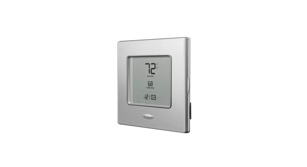
Premium Control
Installation and User Guide
READ AND SAVE THESE INSTRUCTIONS
The illustrations in this document are generic; your control appearance may be slightly different from the ones shown.
![]() WARNING
WARNING
ELECTRICAL SHOCK HAZARD
Failure to follow this warning could result in personal injury or death. Electrical wiring must be done by qualified personnel in accordance with all applicable codes and standards. Before connecting wires, unplug the unit or switch power off at the service panel and lock service disconnecting means to prevent power from being switched on accidentally. Always wear safety glasses and gloves while performing these instructions.
![]() CAUTION
CAUTION
UNIT OPERATION HAZARD
Failure to comply with the following can cause erratic operation of the control and/or unit:
– Never install more than one main wall control per ventilation unit.
– Keep control of low voltage wiring at least 1 foot (305 mm) away from motors, lighting ballast, light dimming circuit, and power distribution panel. Do not route control wiring alongside horsepower wiring.
– Ensure the wires are securely connected.
![]() CAUTION
CAUTION
PROPERTY DAMAGE HAZARD
Failure to comply with the following can cause damage.
If ducts have to go through unconditioned space (e.g.: attic), always use insulated ducts to prevent condensation formation inside and outside ducts, which could cause material damage and/or mold growth. Moreover, if fresh air to the building duct and/or stale air from the building duct goes/goes through an unconditioned space, the unit must be set to operate continuously in cold conditions (below 10°C/50°F). Continuous air movement inside ducts will prevent condensation formation. The unit can be stopped temporarily for maintenance and/or repair purposes in such conditions. (Refer to the main unit Installer Manual for more details.)
This control is compatible with all AI and N series units.
- Unplug the ventilation unit.
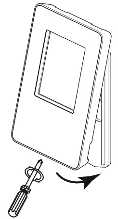
- Unscrew the screw located on the underside of the wall control. Separate the front module from the mounting plate by lifting its bottom part.
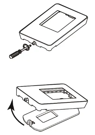
A200547
NOTE: If the control is to be installed in an electric box, do not perform steps 3 and 4. - Using the mounting plate, mark the hole opening and screw locations at the desired height on the wall.
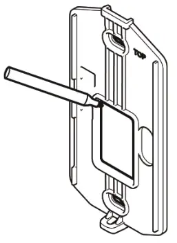
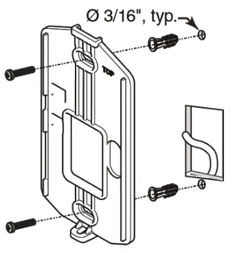
A200548 - Cut the hole opening using the mark previously drawn (1/8″ outside the mark is recommended). Drill both screw holes (3/16″ Ø) in-wall and insert the wall anchors (included).
 KVACN0101(B, C)PC: Installation and User Guide
 - Fix the mounting plate to the wall using the screws provided.
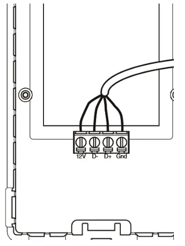
- Strip the end of the cable to access the 4 wires (about 3″). Strip the end of each wire (about 1/4″). Connect the wires to the terminals, regardless of the wire color. Note which wire color has been chosen for each terminal.
 CAUTIONUNIT OPERATION HAZARD
Failure to comply with the following can cause erratic operation of the control and/or unit.
Be careful not to pinch wires when reinstalling the front module on the mounting plate. - Install the front module on the mounting plate. Fix both parts by screwing the screw on the underside of the wall control.
A200551 - Perform the electrical connection to the terminal connector of the unit, as shown below. For more details, refer to the installation manual of the ventilation unit.
NOTE: To avoid miswiring, refer to the notes taken at step 6 to match the wire color with the right terminal.
NOTE: Some features may not be available on all units. The temperature displayed on the Premium control may vary by 5ºC (9ºF) (more or less) compared to the outside temperature since the temperature sensor is located inside the unit to ensure a reading that optimizes artificial intelligence algorithms.
NOTE: The SMART mode uses indoor relative humidity level and outdoor temperature to manage the air exchange with the outdoors, in order to enhance comfort in the house. See figure.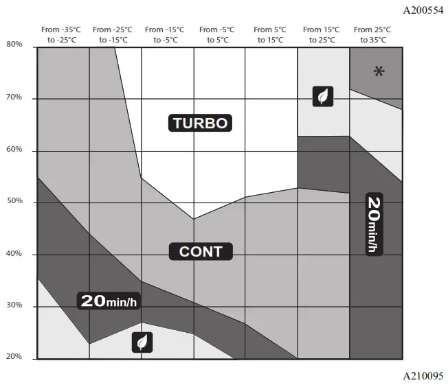
the manufacturer reserves the right to change, at any time, specifications and designs without notice and without obligations.
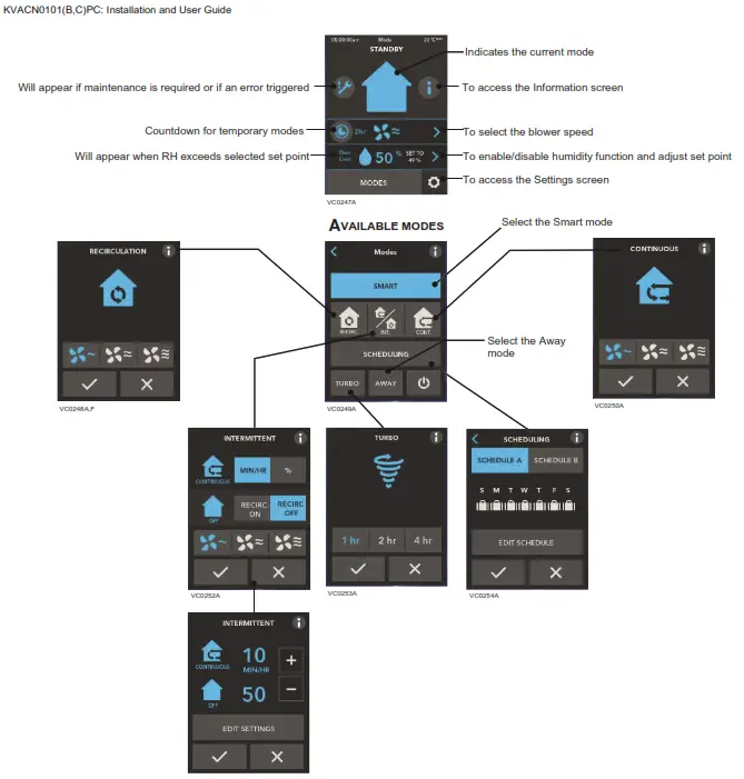
 | To access the next screen |
 | To access the previous screen |
 | To confirm |
 | To exit the screen without saving |
 | To get more information on the action(s) to perform on the corresponding screen |
TROUBLESHOOTING
PROBLEM | POSSIBLE CAUSE(S) | OLUTION(S) |
| The screen is not powered | The ventilation unit is not powered | Plug the ventilation unit |
| Miswiring/Damaged wire/Contact between wires | Check the wall control wiring | |
| The connector J15a is not connected properly | Check J15a connector connection | |
| The wall control is not operational or defective | Check if it uses the same isolated power a circuit as the unit on the electronic board | |
| Replace the electronic assembly | ||
| The screen is powered but displays an error of 50 | Miswiring/Broken wire | Check the wall control wiring |
| The touch screen does not work for all the keys | Defective control | Replace the electronic assembly |
© 2021 Carrier. All rights reserved.


