![]()
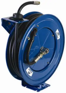
SINGLE PEDESTAL
METAL HOSE REEL
INSTRUCTION MANUAL
Includes models
MAS1020-01
MAS1220-01
MOS1220-01
MGS0615-01
A) Pull out some hose and let reel latch.
B) Remove the 4 bolts that attach the guide roller bracket to the support post.
C) Rotate guide roller bracket to correct position, then replace all bolts and tighten.
TYPICAL MOUNTING POSITIONS


WALL CEILING FLOOR
Introduction
Thank you for purchasing a Heavy Duty Metal Hose Reel.
The range of single pedestal reels have been designed using the highest quality, heavy gauge materials and are fitted with purpose specific hose and swivels. Models available are for Air/Water, Oil and Grease
Important Information
PLEASE READ THIS SAFETY INFORMATION
CAREFULLY BEFORE USE.
Read and retain this instruction manual to assist you in the operation and maintenance of this product.
‘Cautions’ are listed throughout this manual to advise of actions that may cause damage to your equipment.
![]() CAUTION
CAUTION
Make sure the line pressure does not exceed the rated operating pressure of your model hose reel, refer specifications.
![]() CAUTION
CAUTION
Exposure of the skin directly to pressurized air or fluid could result in severe bodily injury.
![]() CAUTION
CAUTION
Before carrying out any maintenance turn off and disconnect the supply line to the reel and carefully release the hose line pressure.
Installation Procedure
1) For overhead ceiling mounting: Install reel at least 3m (10 feet) above the floor.
2) You will need to purchase the appropriate hardware for mounting your new reel.
3) The reel base has four 1/2” (12.7mm) drilled holes for mounting on a suitable flat surface.
4) The reel is supplied with a hose guide roller bracket. The roller bracket position may be changed depending on the reel mounting position. Figure 2 shows “ Typical mounting positions”. If the bracket position needs to be changed, do the following:
5) Using the four holes in the base, mount the reel in the desired location. Be sure to use the appropriate hardware and tighten securely.
6) Apply Teflon tape or pipe sealant to supply line threads, attach to reel and tighten. The other end of the oncoming line can now be connected to the desired supply source. Tighten stopper bolts, and unlatch the reel.
7) Apply Teflon tape or pipe sealant to the outlet fitting on the hose, then attach the desired tool or nozzle. Check connections for leakage, also check hose reel for correct operation. (See Operation section)
8) If hose stopper adjustment is required, pull hose from the reel and allow to latch at desired length. Loosen stopper bolts and slide stopper to a position close to the hose guide. Retighten stopper bolts and check operation.
HOSE INSTALLATION
1) Securely stabilize the reel.
2) Facing the swivel fitting side of the reel, turn the drum clockwise by hand until the rewind spring is tight, and the drum has latched. As an extra precaution while installing hose, secure drum in the latched position.
3) Insert end of hose through roller guides and feed through the opening in the drum flange.
4) Use Teflon tape or pipe sealant on hose fitting threads, screw fitting into swivel and tighten. Note: To avoid damage to the swivel, use a wrench to support the swivel shaft while tightening the hose.
5) Attach hose stopper on the other end of hose, near the outlet fitting.
6) Carefully release drum latch, and slowly allow the hose to rewind into the reel.
Note: Final spring tension adjustment is accomplished by adding wraps of hose around the drum (to increase tension) or taking wraps off hose (to decrease tension). Refer to ‘Adjustment of Spring Tension’.
Maintenance Procedures
OPERATION
1) Check reel for correct operation by slowly pulling out the hose. A “clicking” noise will be heard every half revolution of the drum.
2) To latch the reel, pull out the hose and allow it to retract after hearing the first, second or third “click”.
3) To unlatch, slowly pull out the hose until the “clicking” noise stops, then let the hose retract until the hose stop rests against the hose guide.
![]() CAUTION
CAUTION
Always hold on to the hose while it is retracting.
4) Periodically check the hose condition for wear or damage, and check the swivel fitting for leakage. Replace any worn, damaged or leaking parts.
ADJUST SPRING TENSION
1) Pull out approximately 6ft or 2m of hose and allow the drum to latch.
2) Remove hose stopper from hose, and feed hose back through guide.
3) Wrap the hose one time around the drum to increase tension or un-wrap hose one time to decrease tension.
4) Re-insert hose through guide, and install stopper onto hose end.
5) Unlatch the drum and check tension. Pull hose from reel, and adjust stopper position if necessary,
REPLACEMENT OF SWIVEL SEALS
1) Turn off and release hose line pressure
2) Disconnect supply line from swivel inlet
3) Using the correct size spanner, unscrew the swivel shaft and remove the complete swivel assembly from the reel axle
Note: Swivel seals on grease the reel cannot be replaced.
4) Remove circlip from swivel, and take apart. The swivel can be removed from the reel, but this is not necessary unless installing a new swivel.
5) Replace the seals and reassemble Swivel.
6) Use Teflon tape or thread sealant on thread connections when re-fitting swivel to reel.
7) Re-connect inlet supply line, and check all connections for leaks.
REPLACEMENT OF HOSE
1) Turn off and disconnect the supply line and release hose line pressure.
2) Pull out all the hose and lock the reel in this position.
![]() CAUTION
CAUTION
Make sure the reel drum is securely locked and cannot rotate back.
3) Remove two hose clamps from hose on drum flange.
4) Carefully disconnect hose from swivel joint on side of reel, or male fitting in axil center and remove old hose.
5) Feed new hose through guide and opening in drum, and connect swivel. Re-install two hose clamps, on inside and outside of drum flange. Install stopper on other end of hose in same position as before.
6) Carefully release the drum latch, and slowly allow the hose to rewind into the reel.
Note: For final spring adjustment refer to section “Adjust Spring Tension”.
REPLACEMENT OF SPRING CANISTER
1) Pull out the hose approximately 1m (3ft) and latch reel.
2) Remove the outlet nozzle, gun or tool and hose stopper.
3) Carefully unlatch the reel and firmly hold the drum. Allow the drum to slowly unwind until it stops.
4) Remove the swivel, circlip and spacer.
5) Remove the top four nuts ONLY located on the support post side or the drum.
![]() CAUTION
CAUTION
Do not attempt to remove the spring canister nuts.
(Located under the nuts that hold the spring canister in place)
6) Pull the spring canister off the drum shaft.
7) Reverse the above procedures to re-assemble.
8) Re-tension the reel by turning the drum three complete turns clockwise (from the swivel side) and latch the drum.
9) Feed the hose through the hose guide, fit the hose stopper, then unlatch the drum and allow the hose slowly to retract
REPAIR LATCH PAWL
1) Remove the hose stop and allow the drum to release all its tension with the hose on the spool.
2) When there is no tension on the spring, the main axle nut on the pedestal side can be released and the drum with hose removed exposing the latch pawl and its associated components.
3) To re-tension after any repairs have been made and after the drum has been reassembled to the pedestal, follow the “Adjust Spring Tension” instruction.
Troubleshooting Guide
| TROUBLE | CAUSE | REMEDY |
| Hose will not fully retract | A) Outlet nozzle, gun or tool is too heavy | A) Add spring tension. See ” Adjust Spring Tension” |
| B) Spring is fatigued | B) Add spring tension. See ” Adjust Spring Tension” Replace Spring canister if required, see “Replacement of Spring Canister” | |
| C) Replacement hose is to long | C) Fit correct length hose (Refer Hose to specifications) | |
| Hose w ill not retract at all | A) Spring has broken or has lost all tension | A) Replace Spring canister. See “Replacement of Spring Canister” |
| Reel will not latch | A) Incorrect operation | A) Reel latches on first second or third “click”. After the third click the reel automatically rewinds |
| B) Latch assembly is worn. | B) Replace the latch assembly | |
| Fluid leaks from the swivel | A) Swivel seals are worn | A) Replace swivel seals. See ” Replacement of Swivel Seals”. |
Product Specifications
| Model | MAS1020 | MAS1220 | MOS1220 | MGS0615 | |
| Description | AIR | AIR | OIL | GREASE | |
| Hose Specifications | I.D | 3/8″ (10mm) | 1/2″ (12.5m m) | 1/2″ (12.5m m) | 1/4″ (6mm |
| Length | 20m | 20m | 20m | 15m | |
| Max Working Pressure | 300 PSI | 300 PSI | 2000 PSI | 5000 PSI | |
| Reel | colour | Blue | Blue | Blue | Blue |
| Reel Inlet | Thread Size | 3/8″ BSP | 1/2″ BSP | 1/2″ BSP | 1/4″ BSP |
| Hose Outlet | 3/8″ BSP | 1/2″ BSP | 1/2″ BSP | 1/4″ BSP | |
| Max Operating | Temperature | 60°C | 60°C | 100°C | 100°C |
| Weight | 21/23 kg | 21/23 kg | 21/23 kg | 21/23 kg |
MATERIAL SPECIFICATIONS
| AIR / WATER | OIL | GREASE | |
| SWIVEL SHAFT | BRASS | BRASS | BRASS |
| SWIVEL BODY | BRASS | BRASS | BRASS |
| SEAL TYPE | O’RING | O’RING | O’RING |
| SEAL MATERIAL | NITRILE (NBR) | VITON | VITON |
| REEL BODY | POWDER COATED MILD STEEL | POWDER COATED MILD STEEL | POWDER COATED MILD STEEL |
| HOSE MATERIAL | PVC | RUBBER | RUBBER |
Spare Part Diagram
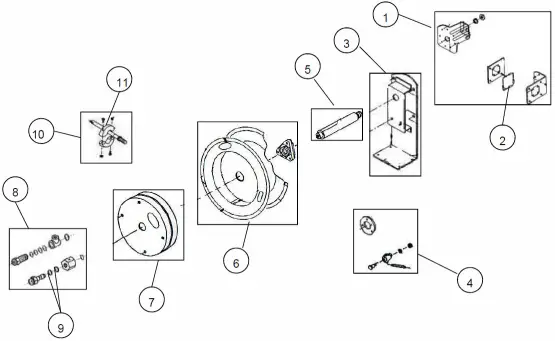
Spare Part Listing
| Item no | Order for replacement Part or set | No Off | Description |
| 1 | n/a | 1 | Guide Arm and Roller Set |
| 2 | SK131s | 1 | Roller mouth assembly |
| 3 | n/a | 1 | Support Post |
| 4 | SK133s | 1 | Latch Set |
| 5 | n/a | 1 | Drum Shaft |
| 6 | n/a | 1 | Drum Assembly |
| 7 | SK136s | 1 | Spring Canister |
| 8 | SK138s | 1 | Swivel Assembly (Air / Water) 3/8″ |
| 8 | SK139s | 1 | Swivel Assembly (Air / Water / Oil) 1/2″ |
| 8 | SK140s | 1 | Swivel Assembly (Grease) |
| 9 | SK141s | 1 | Swivel Seal Set (Air / Water / Oil) |
| 10 | MA142s | 1 | Hose Assembly (Air / Water / ) 3/8″ |
| 10 | SK143s | 1 | Hose Assembly (Air / Water / ) 1/2″ |
| 10 | SK144s | 1 | Hose Assembly (Oil ) 1/2″ |
| 10 | SK145s | 1 | Hose Assembly (Grease) |
| 11 | HPA22SG | 1 | Hose Stopper (Air / Water) 3/8″ |
| 11 | RHA42s | 1 | Hose Stopper (Air / Water/ Oil) 1/2″ |
| 11 | Z10s | 1 | Hose Stopper (Grease) |
 Note:
Note:
This product should be disposed of according to all applicable local and national government environment regulations and guidelines.
![]()
Macnaught Pty Limited
ABN 66 000 075 785
41-49 Henderson Street
Turrella NSW 2205 Sydney Australia
Postal Address PO Box 90
Amcliffe NSW 2205 Sydney Australia
T : +61 2 9567 0401
F : +61 2 9597 7773
W: www.macnaught.com.au
For Warranty Terms and Conditions see macnaught.com.au
For a list of Australian Service Centres see macnaught.com.au
SK110 Issue 10 © 2022


