HIKVISION Indoor Station Touch Screen WiFi Installation Guide

Symbol Conventions
The symbols that may be found in this document are defined as follows.
| Symbol | Description |
| Danger | Indicates a hazardous situation which, if not avoided, will or could result in death or serious injury. |
| Caution | Indicates a potentially hazardous situation which, if not avoided, could result in equipment damage, data loss, performance degradation, or unexpected results. |
| Note | Provides additional information to emphasize or supplement important points of the main text. |
1 About this Manual
Get the manual and related software from or the official website (http:// www.hikvision.com).
| Product | Model |
| Network Indoor Station | DS-KH8350-WTE1,DS-KH8350-TE1 |
Scan the QR code to get the Scan the QR code to get the operation
configuration guide for detailed guide for detailed information.
information.
2 Appearance
Front Panel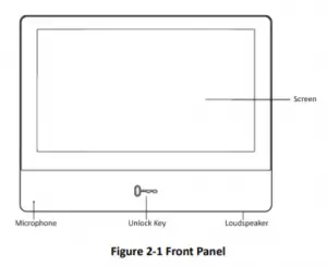
Rear Panel
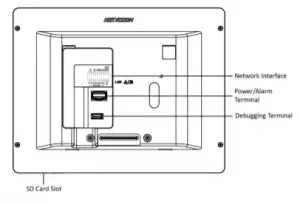
Figure 2-2 Rear Panel
Network Indoor Station Installation Guide
Note
- The Unlock key is valid only when does the indoor station speak with the door station or open the live view of the door station.
- You can not use the debugging terminal.
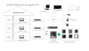
3 Typical Application
4 Wiring Description
There are 20 pins in the terminal on the rear panel of the indoor station: 2 RS-485 pins, 2 power pins, 2 GND pins, 2 alarm output pins, 8 alarm input pins, and 4
reserved pins.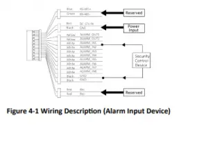
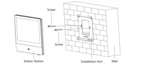
5 Installation
It supports wall mounting. There are two installation modes.
5.1 Installation Accessory Description
The wall mounting plate is required when installing the indoor station on the wall. The dimension of wall mounting plate is shown below.
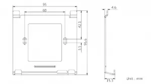
Figure 5-1 Wall Mounting Plate
5.2 Wall Mounting
Before You Start
- Make sure the device in the package is in good condition and all the assembly parts are included.
- The power supply the indoor station supports is 12 VDC. Please make sure your power supply matches your indoor station.
- Make sure all related equipments are power-off during the installation.
- Check the product specification for the installation environment.
Steps
- Fix the wall mounting plate to the wall with 2 supplied screws.
- Put the indoor station on the holder of the wall mounting plate.

Figure 5-2 Installing the Plate


te1 User Guide")


