![]() RAP-6
RAP-6
ISTRAP6
V. 04.2008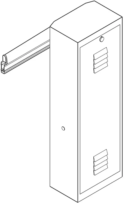

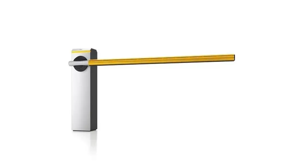
ELECTROMECHANICAL BARRIER
INSTRUCTION HANDBOOK AND SPARE PARTS CATALOGUE
THIS HANDBOOK IS INTENDED FOR QUALIFIED TECHNICAL INSTALLERS
FEATURES
RAP-6 is an electromechanical barrier designed for use at entrances to: car parks, multi-storey parks, factories, public administration buildings, hospitals, apartment blocks, etc..
It consists of a box which houses the gearmotor and the electronic control unit.
Movement is irreversible with the possibility of manual release.
Optional accessories
Mobile fence-type frame Jointed support foot
Rectangular bar L = m6.25
Round-profile bar L=6.25m
Fixed bar rest
| TECHNICAL DATA | U.M. | RAP-6 |
| Line voltage | Va c | 230 |
| Motor power supply | Vdc | 24 |
| Max. input curren | A | 1 |
| Max. input power | VA | 200 |
| Nominal torque | Nm | 280 |
| Opening time | sec. | 7-8 |
| Movement | irreversible – irreversibel – onomkeerbaar | |
| Max. angle of rotation | ° | 90 |
| Operating temperature | °C | -10+70 |
| Motor grease | TS-10 | |
| Working intermittence | % | 50 |
| Max. bar length | m | 6.25 |
| Weight | Kg | 55 |
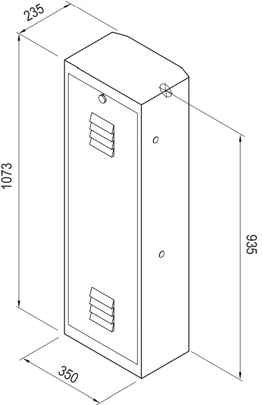
OVERALL MEASUREMENTS
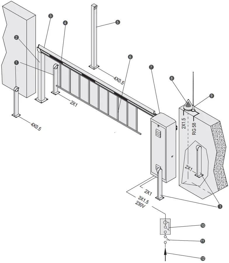
GENERAL LAYOUT
| 1. Photocells 2 Fixed rest 3. Aluminium bar 4. Diamond-shape reflectors 5. Key selector 6. Fence frame | 7. RAP- 6 8. Blinking light 9. Antenna 10. Differential switch 11. On/off switch 12. Power line |
GENERAL ASSEMBLY
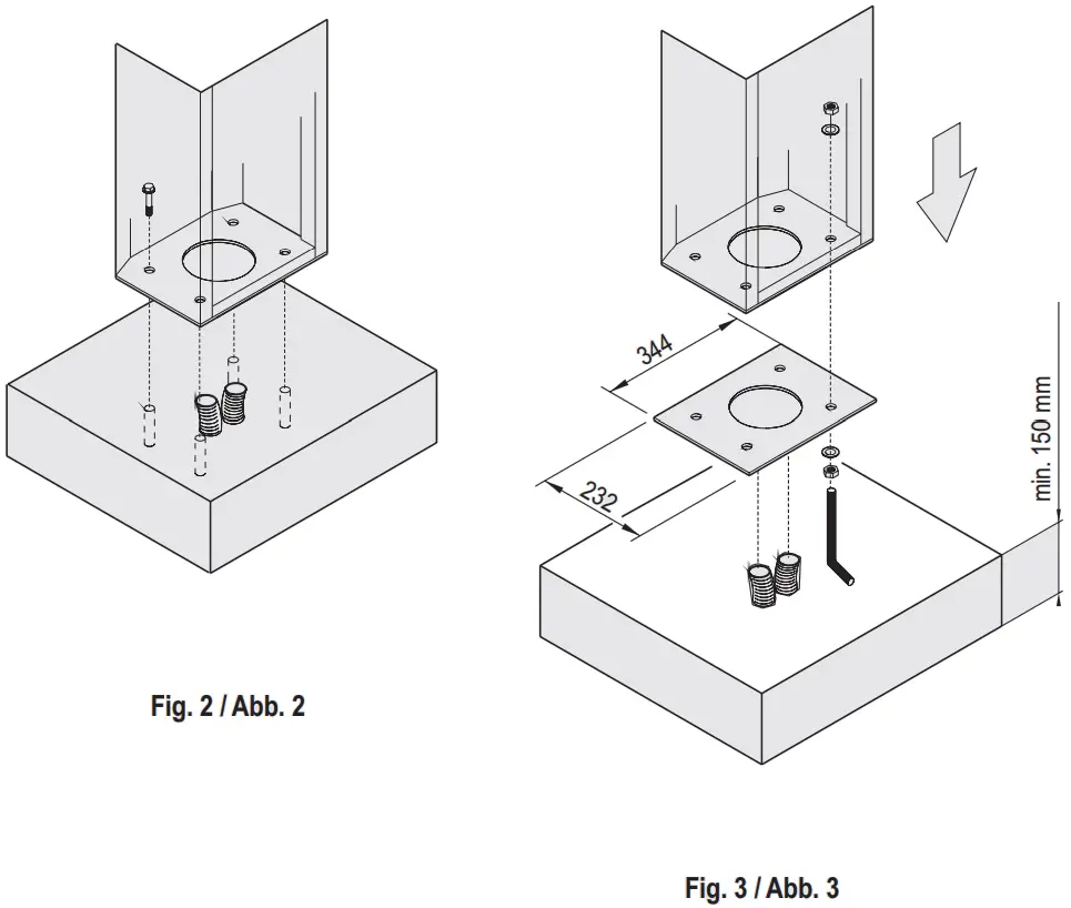
PRELIMINARY CHECKS AND INSTALLATION OF BASE PLATE IN THE GROUND
Before installing, it is advisable to check that the ground where the barrier is to be installed is solid and suitable so that correct operation is not compromised.
If the RAP-6 rests on a solid cement base, it may fixed directly to the ground with 4 screw anchors dia.12 (fig. 2) otherwise fixing may be done using the plate. In this case, proceed as follows:
- Dig a foundation hole, according to the measurements of the foundation plate.
- Place ducts in the hole for the supply and external connection cables to pass through.
- Assemble the plate-rag bolts (fig. 3).
- Bury the ducts and foundation plate in the cement and check that they are horizontal.
- Unscrew the nuts from the 4 rag bolts after the cement has set.
- Position the RAP-6 on the plate, fixing it with the 4 washers and 4 nuts provided.
INSTALLATION OF THE BARRIER
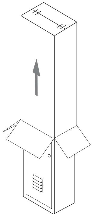
Given the weight of the barrier, it should be handled by several persons.
Unpack as shown in figure.
A 3 x 1.5 power supply cable is recommended for electrical connection.
- Install the barrier as described above.
- Fix the bar to the barrier.
- Put the barrier to the “bar down” position.
- Make the necessary electrical connections.
- Turn on the power supply.
- Adjust the limit stop screws.
- Test operation of the installation.
- Select the required operating modes on the electronic control unit.
LEFT-HAND INSTALLATION
The RAP-4 comes supplied for right-hand use and in the “bar-up” position; the internal counterweight spring is consequently not loaded. The expression “right-hand use” means that the box is assembled to the right of the aperture (seen from inside). (fig. 1).
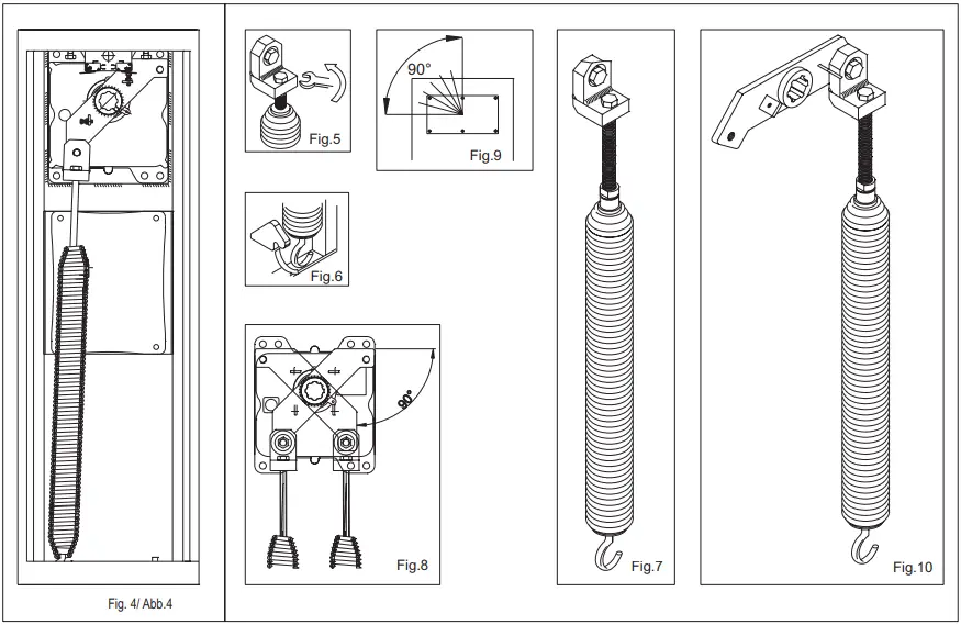
For left-hand use of the barrier, move the spring unit to the opposite side (as in fig. 4).
Proceed as follows for the lefthand use of the barrier:
- Reduce the load of the spring to zero by means of the spring adjustment screw. (fig. 5)
- Disconnect the spring from the lower connector. (fig. 6)
- Extract the spring unit from the barrier unscrewing the screw on the spring equalizing rocker arm (fig. 7)
- Extract the spring equalizing rocker arm from the splined shaft, turn it through approximately 90°, insert it into the shaft again and secure it. (fig. 8)
- From behind the barrier, check that the rotation of the plate has an angle of 90° with the shaft (fig. 9); if necessary check the position of the spring equalizing rocker arm again.
- Make sure that the barrier is in the bar up position.
- Fit the spring unit on the spring equalizing rocker arm, connect the spring to the lower connector (fig. 10), and tension the spring by means of the spring adjustment screw to guarantee that the bar movement is sufficiently assisted.
- Invert the motor wires: open and close; (refer to “terminal boards” for the electronic control unit).
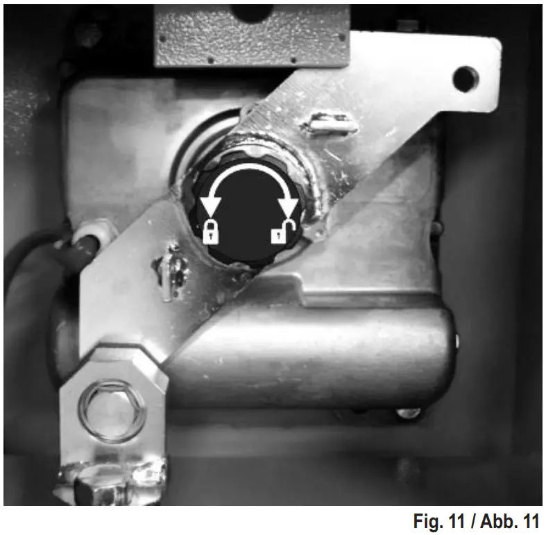
BARRIER RELEASE
To release the barrier, turn the release wheel in a clockwise direction as far as it will go (Fig.11).
To restore the gearmotor, turn the release wheel in an anti-clockwise direction as far as it will go.
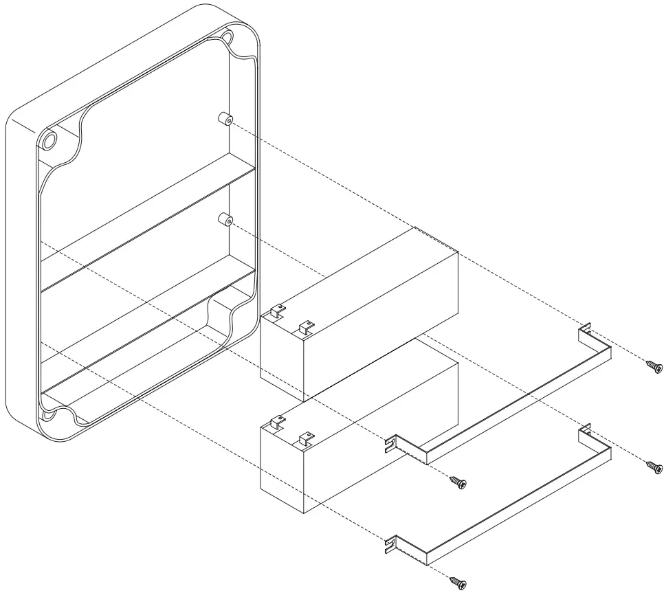
BATTERIES
There is a location for two 12V 1.9 Ah dry batteries inside the control box.
Use the supplied metal clamps and screws to secure the batteries to the lid of the control unit as illustrated in the diagram.
ELECTRICAL CONNECTION
Refer to “terminal boards” in the electronic control unit handbook.
TROUBLESHOOTING
- The barrier does not activate. The electric motor does not work and there is consequently no noise or vibration.
a. Check that the electronic control unit is powered correctly.
b. Check that the fuses are intact.
c. Check with the help of suitable diagnostic instruments that the electronic control unit functions correctly.
d. Make sure that the barrier is receiving power 230Vac – 10%. - The barrier activates but the bar does not move.
a. Check that the thrust of the spring has been correctly adjusted.
b. Check that bar movement is not obstructed.
c. Check that the RAP-6 has not been released.
IMPORTANT RECOMMENDATIONS CONCERNING INSTALLATION
– Only qualified personnel having the legal requirements must install the automation according to the principles of good workmanship and in conformity with the machinery directive 98/37/CE and standards EN 12453 and EN 12445.
– Check that the existing structures (posts, hinges, leaves) are stable in relation to the forces developed by the motor.
– Check that suitably robust limit stops have been installed for end of gate opening and closing.
– Check the state of the cables that are already present in the system.
– Analyse the hazards connected with the automation system and adopt the necessary safety and signalling devices accordingly.
– Install the commands (e.g. the key selector) so that the user is not placed in a hazardous area when using them.
– Upon completion of the installation, test the safety, signalling and release devices of the automation system several times.
– Apply the CE label or plate with information regarding the hazards and identification data on the automation.
– Give the end user the instructions for use, the safety recommendations and the CE declaration of conformity.
– Ensure that the user has understood the correct automatic, manual and emergency operation of the automation system.
– Inform the user in writing (e.g. in the instructions for use) of any unprotected residual risks and of foreseeable misuse.
– Inform the user in writing (in the use instructions for example):
* Of possible non secluded residual risks and of foreseeable improper use.
* To disconnect the power supply when cleaning the area that is automated or when performing small maintenance operations (e.g.: Repainting).
* To frequently control that no visible damage has occurred to the automation, and to inform the installer immediately if damage is noticed.
* Not to allow children to play in the vicinity of the automation.
– Prepare a maintenance schedule for the automation installation (at least once every 6 months for the safety devices), recording the work carried out in a special book.
RAP-6
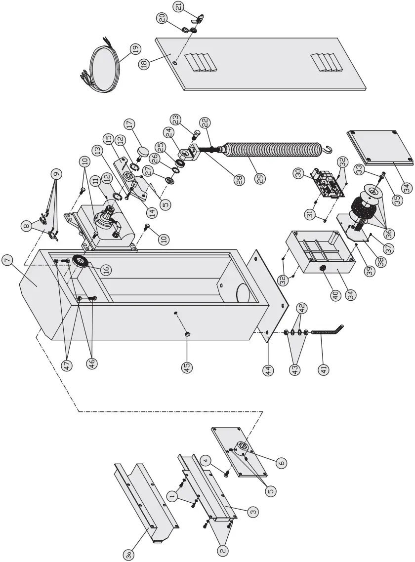
SPAREPARTS CATALOGUE
| Nr. | Cod. | RAP-6spareparts |
| 1 | VTM100X0160CZCE | M10X16UNI5931TCCEGALV.SCREW. |
| 2 | RON10X00PZ | D.10UNI6592GALV.WASHER |
| 3 | SUP0031V | RAP6PAINTEDBARSUPPORT |
| 3a | SUP0030V | RAP6D.90PAINTEDBARSUPPORT |
| 4 | VTM120X0250SZCE | M12X25UNI5933TPSEGALV.SCREW |
| 5 | GR08X008EPZ | M8X8UNI5923GALV.DOWEL |
| 6 | PIASUPASTAB5Z | RAP6GALV.BARSUPPORTPLATE |
| 7 | ARMB5V | RAP6PAINTEDCABINET |
| 8* | MISW30X16L | 30X16MICROSWITCHWITHLEVER |
| 9* | VTT030X0150CZC | M3X15TRI-LOBEDTCGALV.SCREW |
| 10 | VTM120X0200EZ | M12X20UNI5739TEGALV.SCREW |
| 11 | 9224000100 | M4X10UNI5931TCCEGALV.SCREW |
| 12 | SEG38EF | D.38UNI7435SNAPRING |
| 13* | VTM060X0200EZ | M6X20UNI5739TEGALV.SCREW |
| 14* | DA06ZL | M6ALTOGALV.NUT |
| 15 | BIB5Z | RAP6GALV.SPRINGEQUALIZINGROCKERBAOILGUARD |
| 16 | PA60X80X10BA | RAP6ASS.KNOB&WHEEL |
| 17 | MAN0010 | PAINTEDDOORFORBR6CABINET |
| 18 | PORB6V | BR6WIREDMICRO-SWFC |
| 19* | CAB0002 | SWING/IR.RELEASECAP |
| 20 | TAP0005 | SM-SML-TECNOLOCK |
| 21 | SER0006 | D.25UNI7435SNAPRING |
| 22 | SEG25EF | BR6CAMSUPPORTPIN |
| 23 | PE0020 | BR6SPRINGTIGHTENINGCAM |
| 24 | 9262008900 | D.15X42X136302BEARING |
| 25 | CUSC6302B | D.42UNI7437SNAPRING |
| 26 | SEG42IF | BR6CAMSPACER |
| 27 | DIS0019 | BR6GALV.SPRINGADJUSTMENTSCREW |
| 28 | VTREGMOLLA | BR6DRAWSPRING |
| 29 | MO0022 | RAP6CE.CCTx124VdcMOTOR |
| 30 | CECRAP6 | M3THREADEDSPACER |
| 31 | DIS0024 | M3X6uni7985TCGALV.SCREW |
| 32 | VTM030X0060SZC | D.6X24DIN9021GALV.WASHER |
| 33 | RON06X24PZ | TELCOMA274X217X110PLASTBOX+4SCREWS |
| 34 | SPTEL | M6X50CUP-HEADEDSCREW |
| 35 | 9224008100 | 230/22V150VATOROIDFORCE.C |
| 36 | TRA230V150VATOR | M2.9X13UNI6954NICKEL-PLATEDSCREW |
| 37 | VTA029X0013CNC | RAP4GALV.TOROIDPLATE |
| 38 | PIATOR | M4X8UNI8113TRI-LOBEDTPSGALV.SCREW |
| 39 | VTT040X0080SZC | GW50428F20XSEPARE’CABLECLIP |
| 40 | PASF20 | RAP3/BR6GALV.FIXINGTIE |
| 41 | 9182005900 | D.14UNI6592GALV.WASHER |
| 42 | RON14X00PZ | M14UNI5588GALV.NUT |
| 43 | DA14Z0 | BR6GALV.FIXINGPLATE |
| 44 | 9182004700 | SWINGD.16X1COVERPLUG |
| 45 | TAP0037 | 60X80X10 |
| 46 | VTM120X0400EG | M12X40UNI5739TESCREW |
| 47 | DA12Z0 | M12UNI6/S5588GALV.NUT |
ITEMS8;9;13;14and19WITH“T124”CONTROL UNITONLY
RAP-6 GEARMOTOR
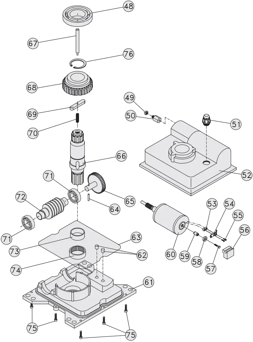
| Nr. | Cod. | RAP-6 GEARMOTOR |
| 48 | CUSC60092RSB | BEARING D.45X75X16 6009 2RS |
| 49 | DA08Z0 | M8 UNI 6/S 5588-8 GALV. NUT |
| 50 | BR0013 | VSF RAP6 BUSHING |
| 51 | PRESSPG11M | PG 11 MAXIBLOCK CABLE CLAMP |
| 52 | CORD900 | ROCK UPPER CASING |
| 53 | RONO3X07PP3 | D.3 D.E.7 H:3 PLASTIC WASHER |
| 54 | ENCODERRAP | RAP MAGNETIC ENCODER |
| 55 | VTT030X0100CZC | M3X10 DIN 7500-C-H TRI-LOBED GALV. SCREW |
| 56 | DIS0023 | 24V RAP6 MOTOR SPACER |
| 57 | VTM040X0160E1 | M4X16 ISO 4017 TE A2 STAINLESS STEEL SCREW |
| 58 | MAG4POLI | 4+4 POLES RE8 PLASTOMAGNET |
| 59 | SUP0026 | TECNO ENCODER ROTATING SUPPORT H=10.3 |
| 60 | MOT0026 | MOT. RAP6 2800 rpm 24Vdc E VSF |
| 61 | COREB5 | RAP6 LOWER CASING |
| 62 | TAP0020 | ROCK D.10X10 RUBBER PLUG |
| 63 | OR253M59X03M53 | D.253.59X3.53 N.41000 O.RING |
| 64 | SPICO4X025G | 4X25 DIN6325 CYLINDRICAL PIN |
| 65 | 9336000200 | ROCK DR.SHA. RED. GEAR |
| 66 | ALBSB5R | RAP 6 SPLINED SHAFT |
| 67 | PE0028 | RAP6 GAL. RELEASE PIN |
| 68 | COR0021 | RAP6 Z30 M3 HELICAL GEAR |
| 69 | LI12X08X063 | 12X8X63 UNI 6604/A TONGUE |
| 70 | MOS2010X38 | SM 10X38 RELEASE SPRING |
| 71 | CUSC62052RSB | D.25X52X15 6205 2RS BEARING |
| 72 | 9230002200 | 24V ROCK WORM |
| 73 | FONARBS | ROLLER CASE BASE |
| 74 | ARHK4516B5 | 45X52X16 ROLLER CASE |
| 75 | VTT060X0200CICE | M6X20 TCCE TRI-LOBED S. STEEL SCREW |
| 76 | SEG45EF | D.45 UNI 7435 SNAP RIN |
DISPOSAL
![]() This product is made up of various components that could contain pollutants. Dispose of properly!
This product is made up of various components that could contain pollutants. Dispose of properly!
Make enquiries concerning the recycling or disposal of the product, complying with the local laws in force.
PROFESSIONAL GARAGE DOOR AND GATE OPERATORS
DECLARATION CE
The manufacturer:
Telcoma sd
Via L. Manzoni, 11 31015 – Z.1. Campidui – Conegliano (TV)
ITALY
DECLARES that the products
GEAR MOTOR DRIVE UNIT “RAP6”
are however conforming to the only applicable parts of this directive;
Directive 73/23/EEC, Directive 93/68/EEC Low Voltage
Directive 89/336/EEC, Directive 92/31/EEC
Directive 92/31/EEC Electromagnetic
Compatibility
The following parts/clauses of the harmonised regulations have been applied:
EN60335-1, EN60204-1, EN 61000-6-3, EN61000-6-1
and for the only applicable parts the norms
EN12445 e EN12453
DECLARATION BY THE MANUFACTURER
(Directive 98/37/EEC, Attachment II, Part B)
Have been constructed to be incorporated in a machine or to be assembled with other machinery to construct a machine as set out in Directive 98/37/EEC
The manufacturer furthermore declares that it is not permitted to operate the products until the machine in which they will be incorporated or of which they will become components has been identified and its conformity with the provisions set out in Directive 98/37/EEC and the national legislation has been declared, i.e. until the products as set forth in this declaration form a single unit with the final machine.
Conegliano, li 03/06/2006
Legal representative Augusto Silvio Brunello
Notes…..
WARRANTY
This warranty covers any failure and/or malfunctioning due to manifacturing faults and/or bad workmanship.
The warranty is automatically invalidated if the product is tempered with or used incorrectly.
During the warranty period, Telcoma srl undertakes to repair and/or replace faulty parts provided they have not been temperd with.
The call-out charge as well as the expenses for dasasembley, packing and transport of the product for repair or replacement shall be charged entirely to the customer.
![]() Telcoma srl – Via L. Manzoni, 11 – Z.I. Campidui
Telcoma srl – Via L. Manzoni, 11 – Z.I. Campidui
31015 Conegliano – (TV) Italy – Tel. +39 0438-451099
Fax +39 0438-451102 – Part. IVA 00809520265
http://www.telcoma.it E-mail: [email protected]


