![]() Installation Drawing: I51
Installation Drawing: I51
Item number: 039-00522, Version 1.0
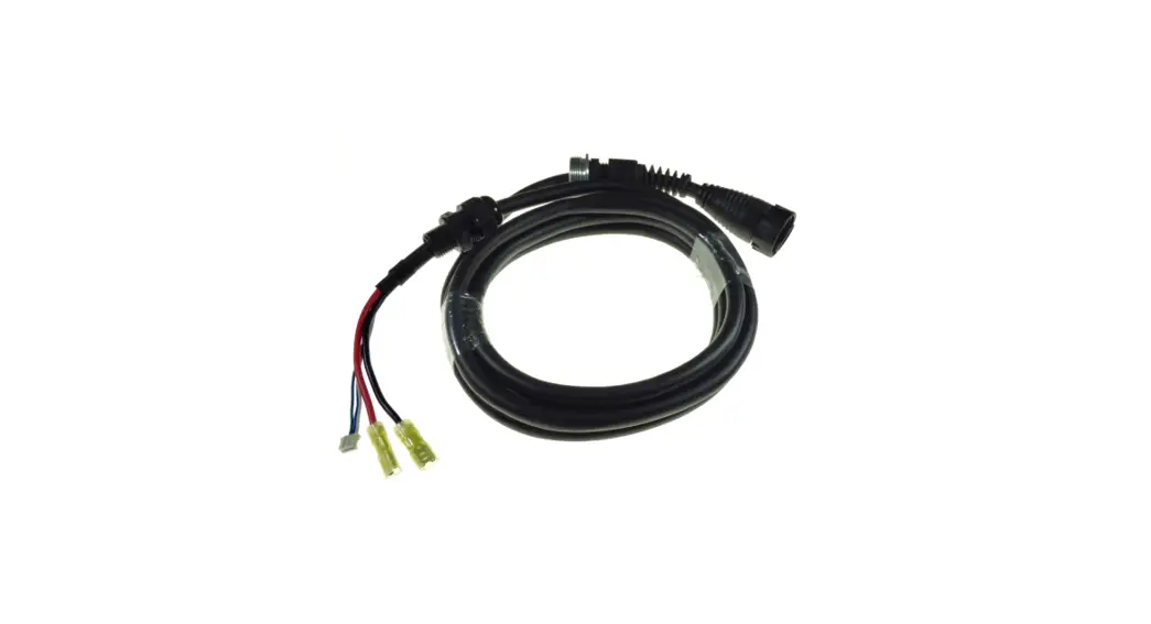
Power cable connection
![]() This installation drawing is an addition to the original operating instructions.
This installation drawing is an addition to the original operating instructions.
Read operating instructions before wiring.
![]() NOTE! Select the correct battery type and enter the correct size of the battery bank in the throttle menu! Check the throttle operating manual for further information.
NOTE! Select the correct battery type and enter the correct size of the battery bank in the throttle menu! Check the throttle operating manual for further information.
NOTE! When using 3rd party batteries, the state of charge (SOC) value is not as accurate as when using Torqeedo batteries. Plan accordingly in reserve to safely reach your destination.
NOTE! The power cable connection of the 3rd party battery bank requires specialist knowledge and may only be carried out by qualified personnel.
If necessary, have the planning and installation carried out by a specialist.
NOTE! Applicable national requirements (e.g. DIN EN ISO 16315, DIN EN ISO 13297, ABYC E-11) are to be observed.
NOTE! Use the Torqeedo power cable or use an adapter to connect to the busbar.
NOTE! Make sure the power supply requirements are maintained. The specifications of the requirements relate exclusively to the terminal to which the Torqeedo system is connected and not to the battery bank. When using additional energy consumers, the battery bank and its wiring must be adjusted accordingly.
NOTE! When connecting the Torqeedo system to the battery bank, make sure that the motor is connected diagonally to the battery bank. See exemplary illustrations on next
page.
NOTE! Note that the lower voltage limit of the technical data specifies the value at which the Torqeedo system switches off. Depending on their properties, 3rd party batteries can switch off earlier or cannot be discharged further than the Torqeedo system allows. Therefore, consider the specifications of your 3rd party batteries when planning the system.
WARNING! Risk of short circuit. The supplied 175 ampere fuse (23) has an interrupting rating of 2000 amperes and is designed for battery banks with a maximum short-circuit current capacity of 2000 amperes. When using battery banks with more than 2000 amperes of short-circuit current, the fuse must be replaced with a appropriate one in terms of interrupting rating.
| Operating requirements for the Torqeedo system | |
| Voltage level in volts lead acid (min. V – max. V) | 37.2 V – 62.0 V |
| Voltage level in volts lithium (min. V – max. V) | 42.2 V – 62.0 V |
| Maximum battery current (permanent) | 154 A |
| Maximum battery current (short-term) | 160 A |
| Fuse load current cable | 175 A |
| Fuse interrupting rating | According to battery bank |
| Cable cross-section for system earthing | Provision and dimensioning by customer |
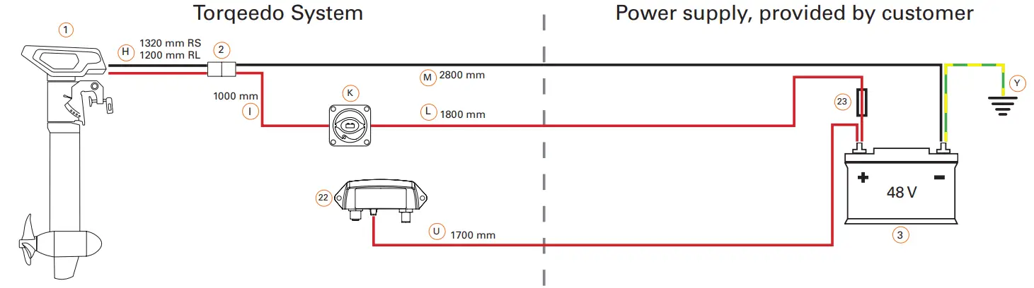
![]() Positive power cable
Positive power cable![]() Negative power cable
Negative power cable![]() 25 mm2 grounding cable
25 mm2 grounding cable
Option with busbars (adapter reqired, not included)
![]() NOTE! Select the correct battery type and enter the correct size of the battery bank in the throttle menu! Check the throttle operating manual for further information.
NOTE! Select the correct battery type and enter the correct size of the battery bank in the throttle menu! Check the throttle operating manual for further information.
NOTE! When using 3rd party batteries, the state of charge (SOC) value is not as accurate as when using Torqeedo batteries. Plan accordingly in reserve to safely reach your destination.
NOTE! The power cable connection of the 3rd party battery bank requires specialist knowledge and may only be carried out by qualified personnel.
If necessary, have the planning and installation carried out by a specialist.
NOTE! Applicable national requirements (e.g. DIN EN ISO 16315, DIN EN ISO 13297, ABYC E-11) are to be observed.
NOTE! Use the Torqeedo power cable or use an adapter to connect to the busbar.
NOTE! Make sure the power supply requirements are maintained. The specifications of the requirements relate exclusively to the terminal to which the Torqeedo system is connected and not to the battery bank. When using additional energy consumers, the battery bank and its wiring must be adjusted accordingly.
NOTE! When connecting the Torqeedo system to the battery bank, make sure that the motor is connected diagonally to the battery bank. See exemplary illustrations on next page.
NOTE! Note that the lower voltage limit of the technical data specifies the value at which the Torqeedo system switches off. Depending on their properties, 3rd party batteries can switch off earlier or cannot be discharged further than the Torqeedo system allows. Therefore, consider the specifications of your 3rd party batteries when planning the system.
WARNING! Risk of short circuit. The supplied 175 ampere fuse (23) has an interrupting rating of 2000 amperes and is designed for battery banks with a maximum short-circuit current capacity of 2000 amperes. When using battery banks with more than 2000 amperes of short-circuit current, the fuse must be replaced with a appropriate one in terms of interrupting rating.
| Operating requirements for the Torqeedo system | |
| Voltage level in volts lead acid (min. V – max. V) | 37.2 V – 62.0 V |
| Voltage level in volts lithium (min. V – max. V) | 42.2 V – 62.0 V |
| Maximum battery current (permanent) | 154 A |
| Maximum battery current (short-term) | 160 A |
| Fuse load current cable | 175 A |
| Fuse interrupting rating | According to battery bank |
| Cable cross-section for system earthing | Provision and dimensioning by customer |
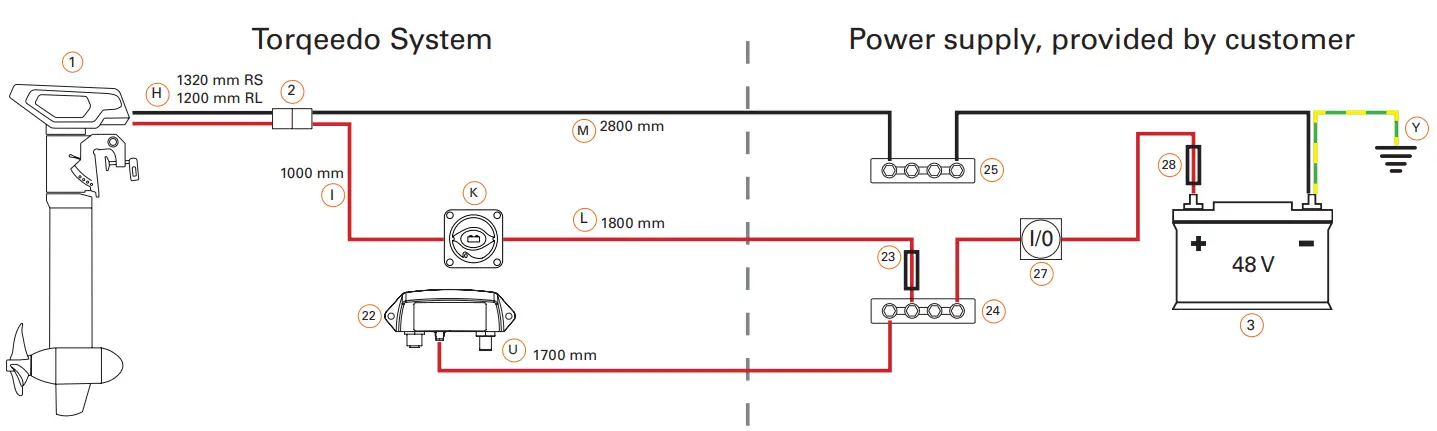
![]() Positive power cable
Positive power cable![]() Negative power cable
Negative power cable![]() 25 mm2 grounding cable
25 mm2 grounding cable
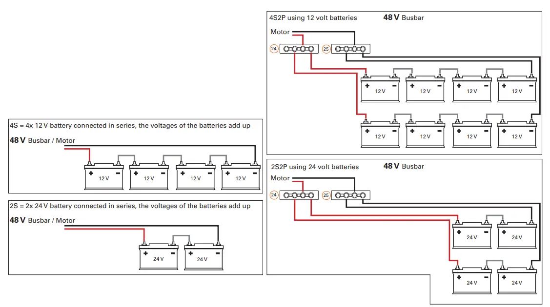
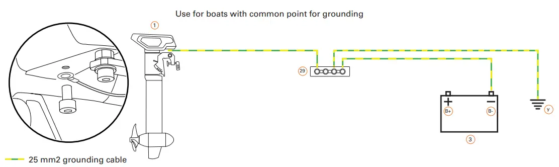
Examples for the wiring of a 48V 3rd party battery bank, provided by customer
![]() NOTE! The power cable connection of the 3rd party battery bank requires specialist knowledge and may only be carried out by qualified personnel.
NOTE! The power cable connection of the 3rd party battery bank requires specialist knowledge and may only be carried out by qualified personnel.
If necessary, have the planning and installation carried out by a specialist.
NOTE! Applicable national requirements (e.g. DIN EN ISO 16315, DIN EN ISO 13297, ABYC E-11) are to be observed.
NOTE! Make sure the power supply requirements are maintained. The specifications of the requirements relate exclusively to the terminal to which the Torqeedo system is connected and not to the battery bank. When using additional energy consumers, the battery bank and its wiring must be adjusted accordingly.
System ground connection
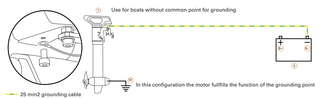
![]() In case using a charger permanently installed in the boat, the charger housing or its AC PE and battery minus pole must be connected to the common grounding point.
In case using a charger permanently installed in the boat, the charger housing or its AC PE and battery minus pole must be connected to the common grounding point.
The AC connection requires specialist knowledge and may only be carried out by qualified personnel.
If necessary, have the planning and installation carried out by a specialist.
NOTE! To charge the batteries in the boat, a land connection in the boat with galvanic isolator or isolation transformer is required according to applicable
national requirements (e.g. DIN EN ISO 16315, DIN EN ISO 13297, ABYC E-11).
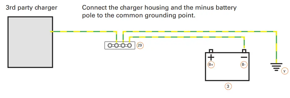
![]() 25 mm2 grounding cable
25 mm2 grounding cable
![]() 8 pin data cable
8 pin data cable![]() 5 pin data cable
5 pin data cable![]() 4 pin data cable
4 pin data cable![]() Backbone TorqLink, 8 pin data cable
Backbone TorqLink, 8 pin data cable![]() Backbone 5 pin data cable
Backbone 5 pin data cable![]() Bus system termination resistor
Bus system termination resistor
Bill of material/Legend/Information
| Pos. | Item number | Name | Remarks See picture for cable length max. 175 A 5000 mm |
| 1 | 1202-10 1263-10 | Cruise 5.0 R Cable set with battery switch Power connector Backbone cable 5-pin | |
| H, I, K, LM | |||
| 2 | |||
| e | |||
| w | |||
| Torqeedo system ground | I min. 25 mm2, not included | ||
| 4 | 1976-00 | TorqUnkThronle | |
| BackboneTorciLink cable 8-pin | 3000 mm | ||
| 22 U f | |||
| 2217-00 000-00858 | TorqUnk gateway set Gateway Gateway Power cable AdaptertCable 5-pin Backbone cable 5-pin TorgLinkTerminator On/Off switch with cable | 1700 mm 200 mm: Do not use in this configuration! 5000 mm Bus termination resistor 2000 mm; Do not use in this configuration! | |
| e 13 18 Y 3 | |||
| 000-05876 | |||
| System ground Battery bank | Provision, dimensioning and correct installs-lion by customer | ||
| 48V: Provided by customer | |||
| 23 | Fuse | Use the delivered by Torgeedo if using the original power cable and Torgeeclo Batteries or use an 175 A fuse with appropiate interrupting rating value | |
| 24 | 1 | I+ Bother (positive pole) | M10 connection: Provided by customer |
| 25 Busbar !negative pole) | M8 connection: Provided by customer | ||
| 27 Battery bank main switch | Provided by customer | ||
| Pos. | Item number | Name | Remarks |
| 28 | Battery bank main fuse | Provision, dimensioning and correct installation by customer | |
| 29 | Common grounding point | Provision, dimensioning and correct installation by customer |
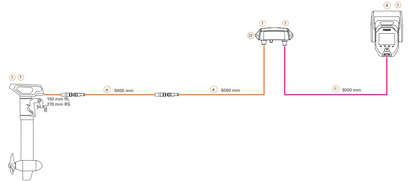
Connect the cruise motor and terminator to each end of the backbone.
The TorqLink bus system requires a terminator (terminating resistor) at both ends of the backbone in order to function correctly.
One of the terminators is located in the „Terminator Single“, „Terminator Twin“, „Throttle 1918-00“, „ Throttle 1976-00“ , the other is built into the cruise motor. Therefore, when installing, make sure that the components „Terminator“ and „Cruise motor“ are each connected to one end of the backbone.
The connection position of the remaining components on the backbone can be freely selected.
Keep the following points in mind when planning:
- An earthing point is required for your Torqeedo system. Take into account the connection and the cables required for this in your planning. The required cable cross-sections can be found in the section Tools, equipment and material.
- First determine and plan the installation positions of all components.
- Measure the required length of the TorqLink backbone.
- Measure the lengths of all required stub lines (cable connection between component and TorqLink backbone).
- When planning, please note that TorqLink drop cables must not be extended. If necessary, plan the TorqLink backbone so that the components can be connected through the TorqLink drop cable without an extension. If necessary, extend the TorqLink backbone to connect a component that is far away; you can find corresponding extensions in our accessories catalogue.
- Cables must be fixed every 400 mm, plan attachment material. In places where fastening is not possible, a scuff guard must be fitted.
- Openly laid cables (e.g. inflatable boat) must be protected with chafing protection, plan sufficient material.
- When planning, please note not to bundle power cables with data or antenna cables (e.g. radios) for other loads.
- Observe the minimum bending radius of the cables when planning.
- If a second earthed onboard power system is available, ensure that both systems use a common earthing point.
- Live parts must be fitted or installed with protection against accidental contact; the necessary installation space must be taken into account during the planning stage.
- Always connect batteries as the last component to the system to avoid short circuits and voltage peaks.
- Do not extend drop cables, extend backbone if necessary.
- Protect plugs and contacts against contamination before installing them.
- Do not pull at the cables.
- Do not twist cables.
- Do not install cables in permanently wet areas such as bilges.
- Install cables free of chafing and not around sharp edges, if necessary, attach chafing protection.
- Maintain bending limits.
- Install plug connections free of tension and load.
Observe the minimum bending radius when laying all cables:
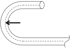
| Torqeedo data cable | 8 x diameter |
| Torqeedo power cable | 8 x diameter |
| Earth cable | see cable manufacturer’s specifica- tions |
| Other power cables | see cable manufacturer’s specifications |
![]()


