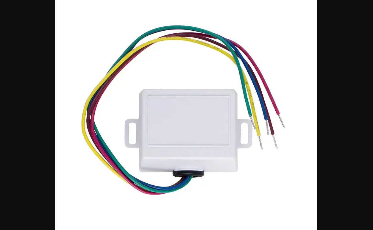

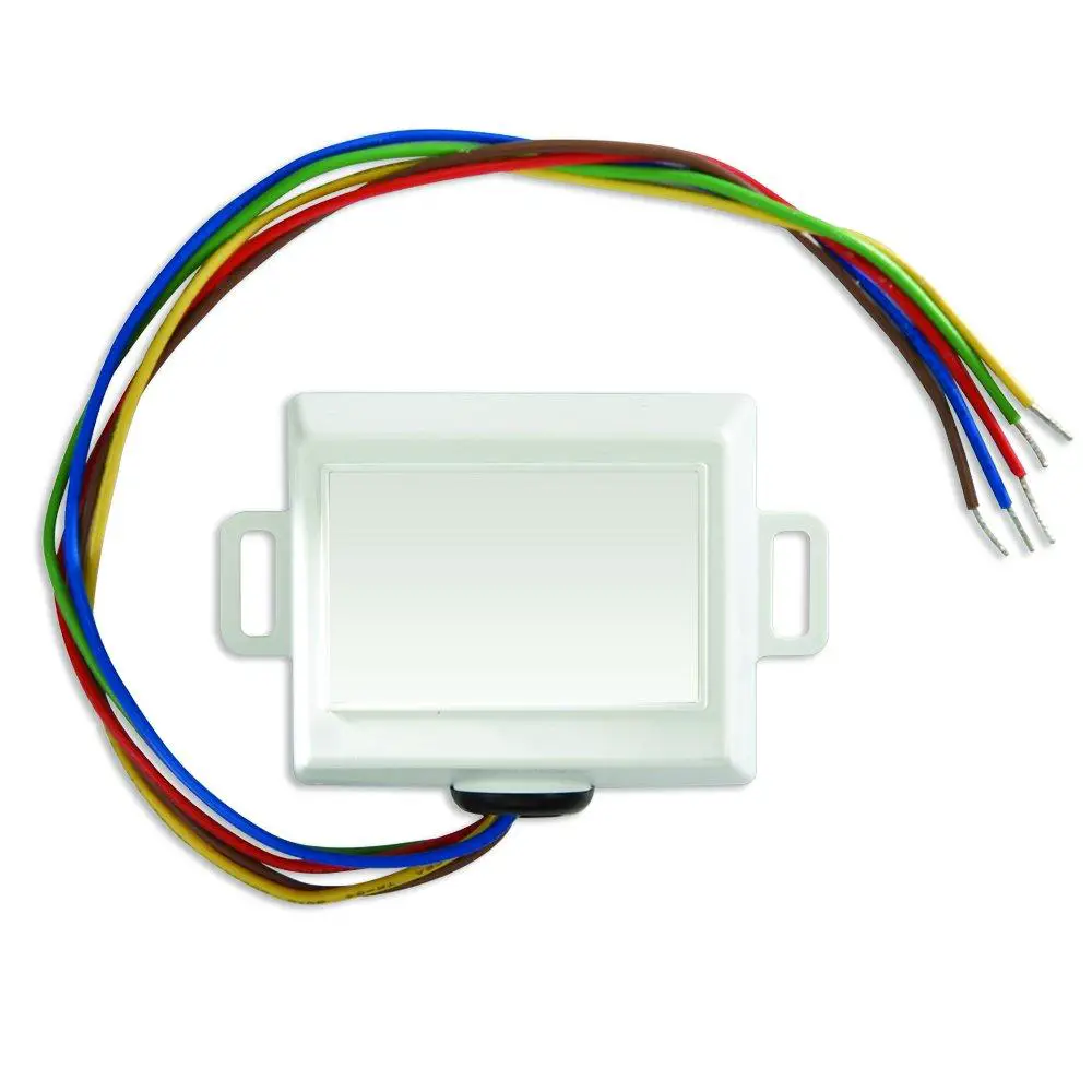
EMERSON Thermostat Common Wire Kit SA11
IMPORTANT: Read entire instructions before starting the thermostat.
SAFETY CONSIDERATIONS
Read and follow manufacturer instructions carefully. Follow all local electrical codes during installation. All wiring must conform to local and national electrical codes. Improper wiring or installation may damage sensor.
Recognize safety information. This is the safety alert symbol. !the safety alert symbol is present on equipment or in the instruction manual, be alert to the potential for personal injury.
Understand the signal words DANGER, WARNING, and CAUTION. These words are used with the safety alert symbol. DANGER identifies the most serious hazards which will result in severe personal injury or death. WARNING signifies a hazard that could result in personal injury or death. CAUTION is used to identify unsafe practices which would result in minor personal injury or property damage.
GENERAL
In applications where additional wiring cannot be run, the Thermostat Common Wire Kit can be used to add a wire to the thermostat. The accessory is also used to fix a broken wire, to make one thermostat work like two, add cooling to a heat only system, or add a common wire to a 4-wire system (the green and yellow wires of the Diode ‘Y’ may not be connected to the R or C terminal of the thermostat).
CONTENTS
- Thermostat Common Wire Kit: 1
- Diode ‘Y’: 1
- Wire Nuts: 4
INSTALLATION
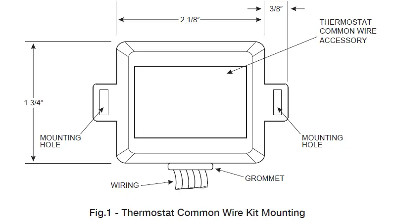
- Step 1 – Location – The Thermostat Common Wire Kit can be mounted inside the HVAC unit or inside the control box. The Thermostat Common Wire Kit should not be installed in a location where the accessory or wiring may be exposed to the elements. Wires running from accessory are 9-in. Long. Thermostat Common Wire Kit should be within 9-in. Of thermostat connections to HVAC terminal block.
If required, mount the Thermostat Common Wire Kit with 2 screws (not provided). See Fig. 1. - Step 2 – Wiring Requirements – The Thermostat Common Wire Kit wiring has the following requirements:
- All system wiring must be in compliance with all applicable local and national codes.
- All wiring should be color coded in conformance with standard recommendations.
- All wiring should be 18- 22-gage, unshielded wire. The Maximum distance between the accessory and the thermostat for 18-gage wire is 100ft. The maximum distance between the Accessory and the thermostat for 22-gage. Wire is 36 ft.
WARNING: Before installing Thermostat Common Wire Kit, turn off all power to the unit. There may be more than one power disconnect. Electrical shock can cause injury or death.
- Step 3 – Accessory Wiring – The Thermostat Common Wire Kit wiring has the following requirements:
Depending on the application and the usage of the Thermostat Common Wire Kit, wiring will vary. Refer to the wiring diagrams in Fig. 2-5for more information on wiring the accessory. - The BLUE wire of the Thermostat Common Wire Kit must always be connected to the BLUE wire of the Diode ‘Y’.
- DO NOT connect the Thermostat Common Wire Kit BLUE, GREEN, or YELLOW wires to the R and C terminals of the HVAC unit, damage may result.
- The GREEN and YELLOW wires of the Diode ‘Y’ should be regarded as extensions of the yellow and green wires of the Thermostat Common Wire Kit. For example, if the YELLOW wire on the Diode ‘Y’ is connected to terminal W on the thermostat to control heat, the YELLOW wire on the Thermostat Common Wire Kit must be connected to W on the HVAC unit to control heat. If the GREEN wire on the Diode ‘Y’ is connected to terminal G on the thermostat to control the fan, the GREEN wire on the Thermostat Common Wire Kit must be connected to G on the HVAC unit to control the fan.
- Use the wirenuts for wire connections to the Diode ‘Y’.
- The wiring diagrams are examples of the uses of the Thermostat Common Wire Kit. Each example may have more than one method of connection that will work. An experienced installer may use different combinations to achieve desired results.
- Do not connect the green and yellow wires of the Diode ‘Y’ to the R or C terminal of the thermostat.
INSTALLATION INSTRUCTIONS
Sample Wiring Diagrams
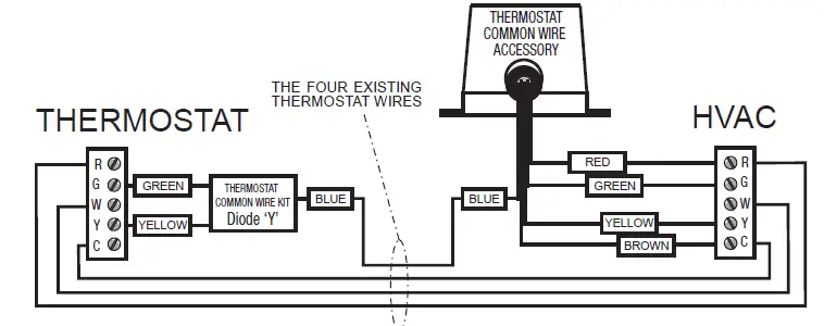
4 existing wires with Thermostat Common Wire Kit to accommodate a thermostat that requires 5 wires.
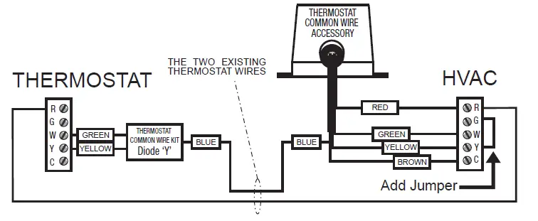
2 existing wires with Thermostat Common Wire Kit to accommodate heating and cooling. No independent fan switching.
A jumper is required across G & Y.
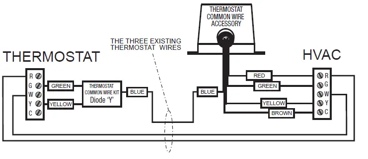
3 existing wires with Thermostat Common Wire Kit to add a cooling to a system that already has heating.
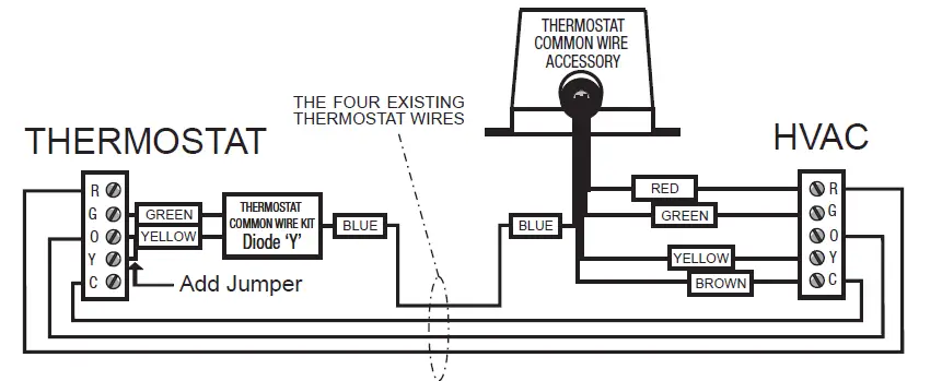
4 existing wires with Thermostat Common Wire Kit to accommodate a single stage heat pump. A jumper is required across the ‘Y’ and ‘O’ thermostat terminals.


