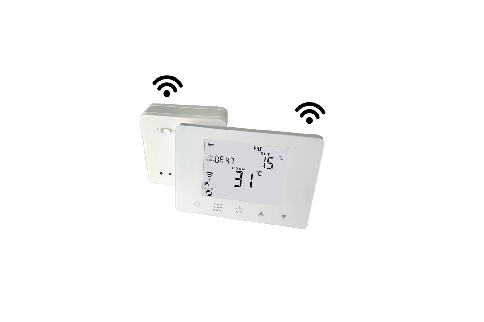
global sources HY09RF Wireless Thermostat User Manual
Technical Data
- Power: Receiver:230Vac 50/60HZ
- Range of temperature display: 0~40°C
Transmitter: 4*AAA Batteries - Display accuracy: 0.5°C
- Insulating condition: Normal environment
- Probe sensor: NTC(10k)1%
- Running program: Set per 1 week as a cycle
- Contact capacity: 5A/250V(WW);16A/250V(WE)
- Output: Switch relay
- Working environment temperature: 0~70°C
- Installation: Wall mounted or on battery seat
- Range of temperature adjustment: 5~35°C
- Size(mm):130*90*25
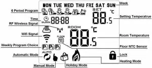
Home Screen
Quick Operation
NO | Icon | Description |
| A |  | Turn ON/OFF |
| B |  |
|
| C |  |
|
| B |  |
|
| D |
|
Time Setting
Power on state, press ![]() to set minute. Second press
to set minute. Second press![]() to set hour. Third press
to set hour. Third press![]() to set week. Press
to set week. Press![]()
![]() , to change value. Press
, to change value. Press ![]() again to confirm.
again to confirm.
Holiday Mode Setting
Power on state, long press ![]() for 3-5 seconds to do holiday mode setting. Press
for 3-5 seconds to do holiday mode setting. Press ![]() or
or ![]() to change “OFF” to “ON”. Then press
to change “OFF” to “ON”. Then press![]() to switch days and temperature, press
to switch days and temperature, press ![]() ,
,![]() to change value. Press again to confirm. If you want to close holiday mode, press
to change value. Press again to confirm. If you want to close holiday mode, press ![]()
Programmable Mode Setting
6 times period setting: 5+2 days(factory default),6+1 days, 7 days
Long press “![]() ” 3-5 seconds to do Programmable Mode Setting . Short press “
” 3-5 seconds to do Programmable Mode Setting . Short press “![]() ” to switch and confirm. Press “
” to switch and confirm. Press “![]() ” and “
” and “![]() ” to adjust value.
” to adjust value.
Power on state, long press “ ![]() ” 3-5 seconds to enter into first time period then set hour. press “
” 3-5 seconds to enter into first time period then set hour. press “ ![]() ” and “
” and “![]() ” to adjust hour, short press “
” to adjust hour, short press “![]() ” to confirm then set minutes, press “
” to confirm then set minutes, press “ ![]() ” and “
” and “ ![]() ” to adjust minutes, press “
” to adjust minutes, press “![]() ” to confirm then enter into temperature setting, press “
” to confirm then enter into temperature setting, press “![]() ” and “
” and “![]() ” to adjust value. Pls follow the steps of first time period to set second time period, thirdly time period ……
” to adjust value. Pls follow the steps of first time period to set second time period, thirdly time period ……
After finish setting , stand for about 10 seconds ,it will save setting then exit .
 |  |  |  |  |  | ||||||
Wake up | Out door | Back home | Out door | Back home | Sleep | ||||||
| 6:00 | 20℃ | 8:00 | 15℃ | 11:30 | 15℃ | 13:30 | 15℃ | 17:00 | 15℃ | 22:00 | 15℃ |
Advanced Setting
Power off state, long press ![]() for 3-5 seconds to do advanced setting. Short press “
for 3-5 seconds to do advanced setting. Short press “![]() ” to switch and confirm. Press “
” to switch and confirm. Press “ ![]() ” and “
” and “![]() ” to adjust options. After finish setting , stand for about 5 seconds ,it will save setting then exit .
” to adjust options. After finish setting , stand for about 5 seconds ,it will save setting then exit .
| NO | Description | Range | Default |
| A1 | Temperature Calibration | -9-+9℃ | 0.5℃ |
| A2 | Switching Differential of Built in Sensor | 0.5-2.5℃ | 1℃ |
| A3 | Switching Differential of External Sensor | 1-9℃ | 2℃ |
| A4 | Children Lock | 0:half lock 1:full lock | 0 |
| A5 | Max temp of External Sensor | 1. 35℃-70℃ 2. When setting temp is lower than 35℃, screen displays【–】, cancel highest temp protection | — |
| A6 | Min temp of External sensor (anti-freeze protection) | 1. 1-10℃ 2. When setting temp is higher than 10℃, screen display【–】, cancel anti freeze protection | 5℃ |
| A7 | Max Temp Setting | 1-10℃ | 5℃ |
| A8 | Min Temp Setting | 20-70℃ | 35℃ |
| A9 | Descaling function | 0:Close descaling function 1:Open descaling function(Function works for 3 minutes every no-operating 100 hours) | 0 |
| AA | Power off Memory | 0:Stay last state 1: Electricity turn off 2: Electricity turn on | 0 |
| AB | Weekly Programmable Function | P1: 5+2 days P2: 6+1 days P3: 7 days | P1 |
| AC | Factory defaults | Display A o, long press until show the whole screen |
Setting IP code
Power off state, long press ![]() for 3-5 seconds to do advanced setting. Short press “
for 3-5 seconds to do advanced setting. Short press “![]() ” to switch and confirm. Press “
” to switch and confirm. Press “![]() ” and “
” and “![]() ” to adjust options. After finish setting , standing for 5 seconds ,it will save setting then exit .
” to adjust options. After finish setting , standing for 5 seconds ,it will save setting then exit .
! Considering battery usage, RF data updates every 20 minutes. If shorten interval, pls use USB power and remove batteries. Follow B05, B06 operation.
| NO | Setting Options | Data Setting Function | Factory Default |
| B1 | IP code low setting | 00-FF | 00 |
| B2 | IP code high setting | 01-FF | 01 |
| B3 | IP matching code | Display”55” means IP match successfully. (When receiver is power-on, press thermostat | 00 |
| B4 | Sensor state | N1:single built-in sensor N3:both built-in sensor and external sensor. (when receiver with external sensor, this | N1 |
| option is automatically recognized and cannot be changed) | |||
| B05 | Minute interval of RF transmission | 1: 1-30 minutes 2:0 B06 | 20 min. |
| B06 | Second interval of RF transmission | 3-30 seconds | 30 s |
Transmitter: transmit every 20 minutes
Receiver Indicator Light
Power-on light : green light
Load light/fault light : red light
- A. When no fault: normally on when load output, light off when no load output
- B. When fault: blinking
- IP fault (IP:FFFF) : Light blinks 2 times every 2s
- No wireless signal within 1h: Light blinks 3 times every 2s
- External sensor fault: Light blinks 4 times every 2s
Sensor fault : Display “E1” or “E2” . Thermostat stop heating until the fault is eliminated
RF matching light: orange light
(B3 IP matching code) When receiver is power-on, orange light is normally on within 10s. And light off when finish matching. When receiver is power-off, orange light is blinking within 10s. Wifi matching light: blue light When power on state, long press receiver button“push” to match wifi. Normally on is EZ mode. Blinking is AP mode. Successive blinking is matching
Wiring Diagram
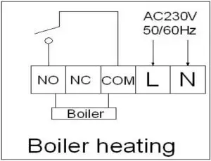
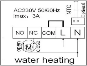
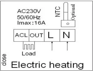
![]() RISK OF ELECTRICAL SHOCK
RISK OF ELECTRICAL SHOCK
Please arrange professional technician to install the product according to drawings and instructions. Disconnect power supply before making any connection. Contact with components carrying hazardous voltage can cause electrical shock.


