![]() Since 1997
Since 1997
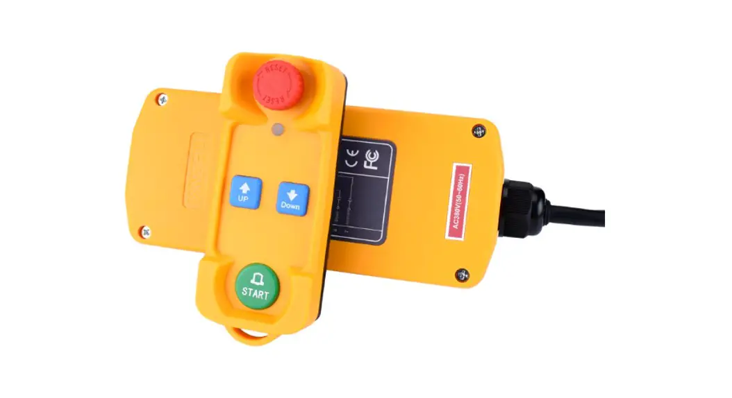
XDL19-F21(XCD)
Industrial wireless remote control
•Convenient* Fast *Control •Connect
Product manual XINDALI INDUSTRIES CO., LTD.
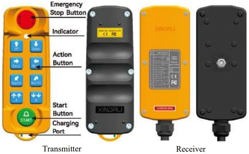
Legend
Technical parameters
| Material of Housing | Glass fiber reinforced nylon |
| Controlling Distance | Within 200M |
| Protection Level | IP65 |
| Controller Power | 3.7V (1200mAh Battery) |
| Receiver Rated Voltage | AC12V-36V. AC220V. AC380V, DC12V-72V |
| Frequen<y Range | 433.99MHz |
| Power of Signal Transmit | slOdBm |
| Receiver Sensitivity | a-110dBm |
| Power Consumption | <5W |
| Cable Length/Size | 1M (can be customized) /0.75mmz |
| Surrounding Temperature | -35°C~+55°C |
| Air relative humidity | <90%RH |
| Air Pressure | 86~106KPa |
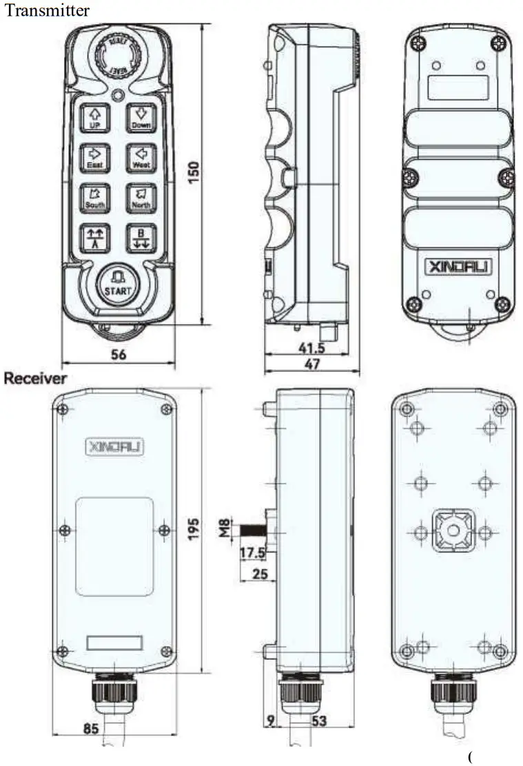
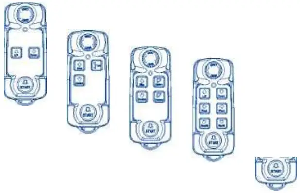
| Controller Dimension | 8 buttons (L150mmxW56mmxH47mm) 6 buttons (L130mmxW56mmxH47mm) |
| Receiver Dimension | L195mmxW85mmxH62mm |
| Weight | Controller 150g, Receiver: 500g. |
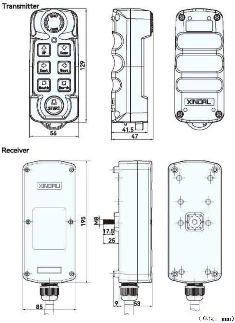
8 push-buttons dimensions
Industrial crane/hoist/hoisting application field wiring diagram
WIRE DIAGREAM
REMOTE CONTROL
MODEL NO.:
XDL19-F21-8RX SIN-.
| 1 | Brown | Power positive |
| 2 | Black | Power negative |
| 3 | Red | Main switch (not connected if not always on) |
| 4 | Orange | Common wire (combine with No. 1 brown wire to connect the positive terminal of power supply) |
| 5 | Yellow | Up |
| 6 | Green | Down |
| 7 | Blue | East |
| 8 | Purple | West |
| 9 | Gray | South |
| 10 | White | North |
| 11 | Pink | Start |
| 12 | Yellow/White | A Go or go slow |
| 13 | Green/White | B Go fast or slow down |
WIRE DIAGREAM
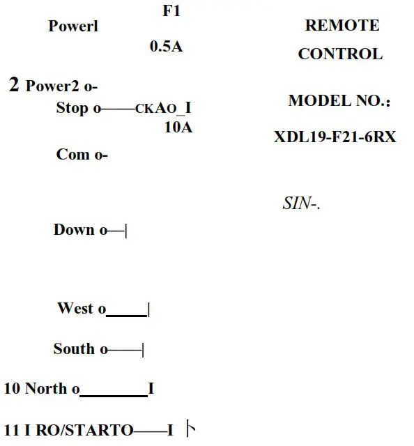
| 1 | Brown | Power positive |
| 2 | Black | Power negative |
| 3 | Red | Main switch (not connected if not always on) |
| 4 | Orange | Common wire (combine with No. 1 brown wire to connect the positive terminal of power supply) |
| 5 | Yellow | Up |
| 6 | Green | Down |
| 7 | Blue | East |
| 8 | Purple | West |
| 9 | Gray | South |
| 10 | White | North |
| 11 | Pink | Start |
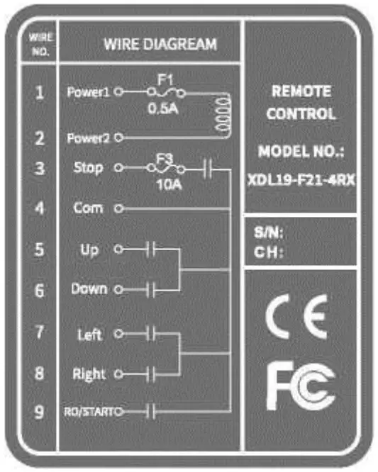 XDL19-F21-4
| 1 | Brown | Power positive |
| 2 | Black | Power negative |
| 3 | Red | Main switch (not connected if not always on) |
| 4 | Orange | Common wire (combine with No. 1 brown wire to connect the positive terminal of power supply) |
| 5 | Yellow | Up |
| 6 | Green | Down |
| 7 | Blue | Left |
| 8 | Purple | Right |
| 9 | Pink | Start |
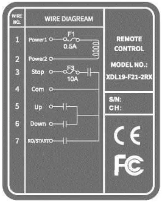 XDL19-F21-2
| 1 | Brown | Power positive |
| 2 | Black | Power negative |
| 3 | Red | Main switch (not connected if not always on) |
| 4 | Orange | Common wire (combine with No. 1 brown wire to connect the positive terminal of power supply) |
| 5 | Yellow | Up |
| 6 | Green | Down |
| 7 | Pink | Start |
S. Wiring diagram of automobile tail board application field
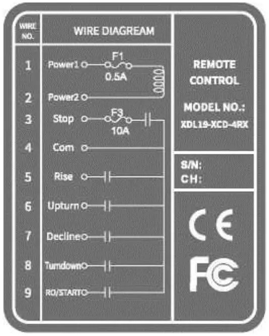 XDL19-XCD-4
| 1 | Brown | Power positive |
| 2 | Black | Power negative |
| 3 | Red | Main switch (not connected if not always on) |
| 4 | Orange | Common wire (combine with No. 1 brown wire to connect the positive terminal of power supply) |
| 5 | Yellow | Rise |
| 6 | Green | Upturn |
| 7 | Blue | Decline |
| 8 | Purple | Turndown |
| 9 | Pink | Start |
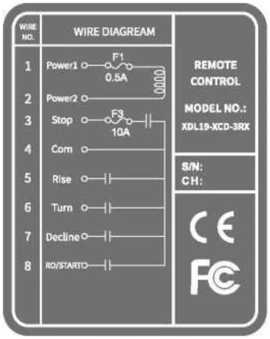 XDL19-XCD-3
| 1 | Brown | Power positive |
| 2 | Black | Power negative |
| 3 | Red | Main switch (not connected if not always on) |
| 4 | Orange | Common wire (combine with No. 1 brown wire to connect the positive terminal of power supply) |
| 5 | Yellow | Rise |
| 6 | Green | Turn |
| 7 | Blue | Decline |
| 8 | Pink | Start |
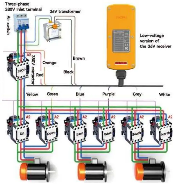
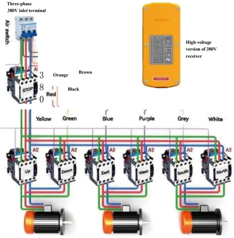
The receiver wiring diagram
Low-voltage of the Receiver 36V contactor diagram
Receiver high-voltage version control 380V contactor diagram
Operating instructions
7.1 A remote control pairing method (factory has been paired, if you need to pair again can be operated according to the following steps):
7.1.1 Must be in the receiver power off premise to the receiver power — enter the pairing state countdown 20S.
7.1.2 Must enter the pairing state when the transmitter is pressed down and then bounced up, press the remote control “START” button for about 6 seconds, the red/green light of the remote control flashes alternately, release the button, the pairing is successful.
7.2 Pairing method of two remote controls (factory paired, if you need to pair again, you can follow the steps below):
7.2.1 The remote control and receiver have a corresponding address code in the factory, the customer needs to provide the address code to replace the remote control or receiver; and the manufacturer will send it to the customer in accordance with the address code matching procedure.
7.3 Key operation (industrial traveling crane / hoist / lifting applications):
7.3.1 Press the “STARRT” start button, the green indicator light will flash, if the red indicator light flashes, the emergency stop button will turn down.
7.3.2 Follow the correct operation of the functions set by each button on the transmitter.
7.3.3 Press the emergency stop button after the operation is finished, and it will automatically enter the low power consumption state.
7.4 Three-button combination operation (automotive tailgate application):
7.4.1 Press the “STARRT” start button, the green indicator light will flash, if the red indicator light flashes, the emergency stop button will tum down.
7.4.2 Tailgate rising operation: single press the “rising” button
7.4.3 Tailboard down operation: single press the “down” button
7.4.4 Tai I board up operation: press and hold the “up” + “flip” button at the same time
7.4.5 Tai I board down operation: press and hold “down” + “flip” two buttons at the same time
7.4.6 Press the emergency stop button after the operation is finished, and it will automatically enter the low power consumption state.
7.5 Four buttons individual operation (automotive tail-board application field):
7.5.1 Press the “START” button, the green indicator flashes. If the red indicator flashed, twist the emergency stop button.
7.5.2 Tail-board up operation: press “Rise” button individually.
7.5.3 Tail-board down operation: press “Decline” button individually.
7.5.4 Tail-board up turn operation: press “Upturn” button individually.
7.5.5 Tail-board down turn operation: press “Turndown” button individually.
7.5.6 After the operation is completed, press the emergent stop button to automatically enter the low power consumption state.
7.6 Indicator Status:
7.6.1 Only red indicator keeps on means charging.
7.6.2 Only green indicator keeps on means charging completed.
7.6.3 Only Yellow indicator flashes means battery under-voltage.
7.6.4 Two-color indicator(Red/Green) flashes alternately means matching.
7.6.5 After the emergency stop button, if you press any other buttons, the two-color indicator will flash red light.
7.6.6 After the start button, if you press any other buttons, the two-color indicator will flash green light.
Quality Warranty Statement
8.1 Quality Assurance:
We guarantees that product fully complies with its published specifications when it leaves the factory. As long as it is properly installed, it can be used normally However, we do not guarantee that the operation of the product will be uninterrupted or error-free.
8.2 Guarantee Period:
This product enjoys a one-year warranty period from the date of delivery to ensure that customers will not have any problems with the product within one year. If it is within warranty period, as long as the product quality is proved to be defective, we are willing to repair it. Any product that needs to be repaired must be sent to the repair point designated by our company. Customer must bear the one-way freight to the repair point, and our repair point will send back the product and bear the return freight within warranty period.
8.3 Items not included:
The above warranty coverage does not include lossy parts such as buttons, relays, fuses, lithium batteries, or damage caused by installation errors, and does not include improper use by customers, irresistible reasons, natural factors, insufficient maintenance, neglect of operating environmental specifications, unauthorized changes, incorrect use, or failure caused by customer’s own disassembly and modification of the structure. Remarks:
浪※ All above mentioned warranties, no other stated or implied warranties. 楽※ The compensation provided by the warranty is the only compensation for the customer; we are not responsible for any direct, indirect, special, incidental or consequential damages.
Precautions
9.1 General Precautions:
- Personnel without professional training shall not disassemble the machine, otherwise, it may cause damage and casualties.
- The manual is only fbr the reference of the user, please consult the manufacturer for detailed technical questions.
- This machine has been strictly tested before leaving the fectory, but it should not be used if it is dangerous and may cause damage.
- After use, the main power supply of the crane should be turned off, and the power of the receiver should be cut off; and the transmitter should be turned off. Then press the emergency stop button to automatically enter the low power consumption state.
- The transmitter should be placed in a safe place, personnel should not press it arbitrarily to avoid accidents.
- The crane should have a main power contactor; limit switch, and other safety facilities.
- Stop using it in case of lightning strike or interference.
- Make sure the transmitter is fully charged and the receiver is powered properly.
- During installation or maintenance, the main power supply of the crane and the power supply of the receiver should be turned off to avoid electric shock.
- The manufacturer may modify the contents of this instruction manual at any time without notice.
9.2 Operator Precautions:
- The user must have received complete training to be familiar with the operation method.
- The user must be in good health, in good spirits, and be able to identify and judge the safety of the operation.
- The operators should pay attention to the indicator light on the transmitter. If the red light is continuously flashing, there may be an abnormality or malfunction, or the battery may be exhausted. At this time, it should be charged immediately.
- Once the equipment is found to be seriously disturbed, the operation should be stopped immediately.
- If the remote control is not used for a long time, press the emergency stop button to low-power consuming status automatically.
- Please note the following emergency procedures before use.
9.3 Precautions for installation:
- Before installation, be sure to turn off the main power to avoid electric shock.
- When installing the receiver; select a location where there is no spark contact, away from motors, relays, cables, frequency inverter; avoid approach to high voltage cable orfacilities to avoid receiver interference with weak signal.
- The receiver must be secured during installation to avoid loosing and falling.
- Make sure to the power supply of the crane and the function settings of the remote control(including relay output) to avoid damage with incorrect wiring.
- The receiver can not be installed in the electric control box. The correct installation method is that fixing the receiver on the top of the electric control box (or external) in appropriate position, then enter the output cable into the electrical control box for correct wiring
9.4 Emergency handling:
When an emergency occurs, please follow the steps below and notify the manufacturer immediately.
- Press the emergency stop button to low-power consuming status automatically.
- Turn off main power of crane.
- Call the manufacturer and find out the reason.
Customer service Hothne: J 0086-577-62795533

XINDALI INDUSTRIES CO., LTD.
All rights reserved!
This manual is compiled by the Technology Research and Development Center of Xindali Industries Co., LTD., and it is only used to display the representative products of the company. Due to internal change, upgrade or adoption of new production process to improve the content of this manual, or necessary improvement or change of printing errors and related information in this manual, we will not disclose it separately. Please contact our technical department directly for any questions.
FCC Statement
This equipment has been tested and found to comply with the limits for a Class B digital device, pursuant to part 15 of the FCC Rules. These limits are designed to provide reasonable protection against harmful interference in a residential installation. This equipment generates, uses and can radiate radio frequency energy and, if not installed and used in accordance with the instructions, may cause harmful interference to radio communications. However, there is no guarantee that interference will not occur in a particular installation. If this equipment does cause harmful interference to radio or television reception, which can be determined by turning the equipment off and on, the user is encouraged to try to correct the interference by one or more of the following measures:
- Reorient or relocate the receiving antenna.
- Increase the separation between the equipment and receiver.
- Connect the equipment into an outlet on a circuit different from that to which the receiver is connected.
- Consult the dealer or an experienced radio/TV technician for help.
Caution: Any changes or modifications to this device not explicitly approved by manufacturer could void your authority to operate this equipment.
This device complies with part 15 of the FCC Rules. Operation is subject to the following two conditions: (1) This device may not cause harmful interference, and (2) this device must accept any interference received, including interference that may cause undesired operation.
RF Exposure Information
This equipment complies with FCC radiation exposure limits set forth for an uncontrolled environment. This equipment should be installed and operated with minimum distance 0cm between the radiator and your body.


