PROTEOR 1M01-P6 Inova Orthopedics Instruction Manual
COMPONENTS INCLUDED
| Designation | Reference | Included / Sold separately |
| Knee | 1M01(-P6) or 1M10(-P6) | Included |
| Locking system | 1M01100 | Sold separately |
| Single-piece trim | 1G13 / 1G21 | Sold separately |
| Extension return | 1R02 | Sold separately For 1M01 and 1M10 only |
DESCRIPTION, PROPERTIES AND ACTION MECHANISM
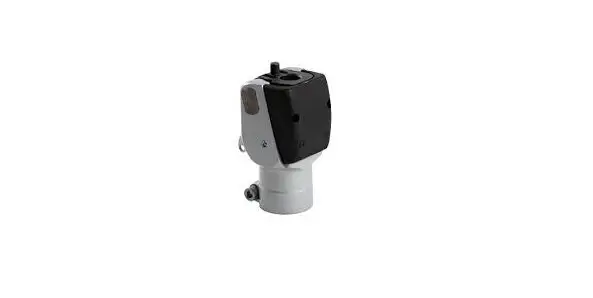
Description
Single-axis lockable knee.
Comes in four versions:
- 1M01 / 1M01-P6: lockable knee with cable (right or left)
- 1M10 / 1M10-P6: lockable knee with release handle
Properties
| Reference | 1M01 | 1M10 | 1M01-P6 | 1M10-P6 |
| Weight | 345 g | 355 g | 375 g | 385 g |
| Height (H) | 13 mm | 14 mm | ||
| Total height (TH) | 99 mm | 102 mm | ||
| Design height (DH) | 58 mm | 59 mm | ||
| Maximum bend | 130° | |||
| Maximum patient weight (Including load borne) | 100 kg | 125 kg | ||
| Distal connector tube | Ø30 mm | Ø34 mm | ||
This device has been tested as per standard NF EN ISO 10328 for a load level of P5 (i.e. 100 kg) for the 1M01 and 1M10, and for a load level of P6 (i.e. 125 kg) for the 1M01-P6 and 1M10-P6, for 3 million cycles, corresponding to a service life of 4 to 5 years, depending on the patient’s activity level.
Action mechanism
This lockable knee has a lock with a settable stop, and a joint friction setting.
INTENDED USERS/INDICATIONS
This medical device is supplied to health professionals (orthopaedic prosthetists), who will train the patient in their use. The prescription is drawn up by a doctor, alongside the orthopaedic prosthetist, to assess whether the patient is suited to using it.![]() This device is for SINGLE-PATIENT use. It must not be reused on another patient.
This device is for SINGLE-PATIENT use. It must not be reused on another patient.
This device is designed only for the prosthetic system for a transfemoral amputee, or amputee with hip/knee disarticulation. It is specifically recommended for low-activity patients (L1), or sedentary patients.
Maximum weight (including load borne):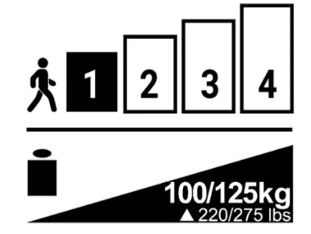
- 1M01 / 1M10: 100 kg
- 1M01-P6 / 1M10-P6: 125 kg
![]() Not suitable for children.
Not suitable for children.
![]() The knee’s maximum bend is 130°. It may however be limited by the socket volume or by the aesthetic coating.
The knee’s maximum bend is 130°. It may however be limited by the socket volume or by the aesthetic coating.
CLINICAL BENEFITS
The device makes it possible to:
- Set the knee friction.
- Set the lock stop.
- Set the socket rotation to +/- 15°.
ACCESSORIES AND COMPATIBILIT
| Reference | 1M01 / 1M10 | 1M01-P6 / 1M10-P6 | |
| Upper joint | Tie-plate | 1K40 | |
| Connectors | 1K160 / 1K163 / 1K03(-P6) / 1K30 | 1K160-P6 / 1K03-P6 | |
| Lower joint | Tube | Ø30 mm | Ø34 mm |
MOUNTING AND FITTING ON THE PATIENT
Alignments
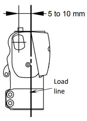
Static alignments:
In the sagittal plane, the load line runs via the Trochanter, between 5 and 10 mm in front of the knee axis.![]() Make sure to respect the patient’s flexum. For the foot, comply with the alignment instructions from the manufacturer.
Make sure to respect the patient’s flexum. For the foot, comply with the alignment instructions from the manufacturer.
In the frontal plane, the load line will run via the middle of the knee and the foot.
Dynamic alignments:
In normal walking, after fitting the cable and the various settings set out below, the knee must be extended during the stance phase.
Check the alignment using an appropriate tool (laser, plumb line, etc.)
Fitting
![]() Tube holding collar tightening torque:
Tube holding collar tightening torque:
- 1M01 / 1M10: 11Nm
- 1M01-P6 / 1M10-P6: 5Nm
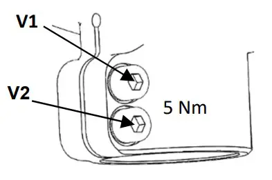
![]() Adhere to the tightening order and torque of the screws on the tube (diameter 34 mm) on the -P6 version:
Adhere to the tightening order and torque of the screws on the tube (diameter 34 mm) on the -P6 version:
- Tighten screw V1 to 5 Nm
- Tighten screw V2 to 5 Nm
- Retighten screw V1 to 5 Nm

Setting
For the patient’s safety, the orthopaedic prosthetist must perform the initial test with the factory settings, between parallel bars.
![]() The foot model used may influence the knee settings. The knee should be set whenever the foot has been replaced.
The foot model used may influence the knee settings. The knee should be set whenever the foot has been replaced.
![]() After any maintenance operation, the knee will need to be set again.
After any maintenance operation, the knee will need to be set again.
Using a 3 mm Allen key, tighten or loosen the screw (1) until you obtain the desired setting.
![]() Systematically check that the knee locks in extension (locking noise and lever free movement amplitude = approx. 2 mm)
Systematically check that the knee locks in extension (locking noise and lever free movement amplitude = approx. 2 mm)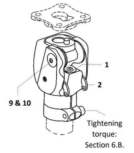
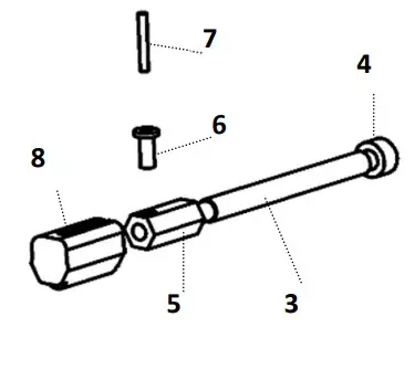
Cable fitted (version 1M01 & 1M01-P6)
- Place the spacer (3) between the branches of the lever (2)
- Insert the screw (4) into the spacer (3)
- Engage the nut (5) onto the screw (4)
- Insert the rivet (6) into the nut hole (5)
- Place the cable (7) in the rivet (6)
- Adjust the length of the cable (7)
- Tighten the screw (4) to lock the cable
- Cut off the excess cable
- Mount the cap (8) on the nut (5)

Friction setting
- Unlock the central screw (9) using a 2 mm Allen key.
- Tighten or loosen the main screw (10) using a 4 mm Allen key.
- Lock the central screw (9): tightening torque 2.5 Nm.
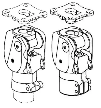
Version change
Switching from 1M01 to 1M10:
Remove the two screws (11), taking care not to lose the joint axes.
Select position A or B for the handle (12).
Mount the clevises (13) on the handle (12).
Engage the ends of the handle (12) into the lever holes (2).
Secure the assembly using the screws 14
Switching from 1M10 to 1M01:
Remove the screws (14), clevises (13) and handle (12). Install the cable as shown above. In place of the screws (14), refit the hex headless screws contained in the cable’s package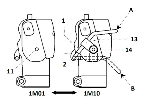
Finishing
![]() The socket must be in contact with the tube holding collar at maximum bend. Any other contact zone is prohibited.
The socket must be in contact with the tube holding collar at maximum bend. Any other contact zone is prohibited.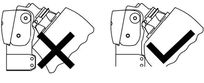
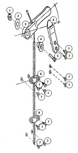
Installing the 1M01100 unlocking system
- Insert the tapped insert (1) into the wood or laminate.
- Assemble the washer (2), handle (3) and ring (4) with the screw (5).
- Cut the sheath to the desired size.
- Insert the cable into the hole in the handle (3), and into the sheath, then fasten it on the lock lever with the desired tension.
- The handle will be angled approximately 30° above horizontal in the locked position.
- Fit one or two bridge fittings (8) using screws or tubular rivets (7).
- Possibly fasten the release holding tab (6) using screws or tubular rivets (7).

DETECTING MALFUNCTIONS
![]() If you observe abnormal behaviour or feel modifications in the device’s properties, or if it undergoes a heavy impact, please consult your orthopaedic prosthetist.
If you observe abnormal behaviour or feel modifications in the device’s properties, or if it undergoes a heavy impact, please consult your orthopaedic prosthetist.
WARNINGS, CONTRAINDICATIONS, SIDE EFFECTS
Warnings
instead. Talc causes deterioration of the mechanical components, which can lead to a malfunction with a risk of the patient falling. PROTEOR disclaims all liability if the knee is used with talc.
![]() There is a risk of the knee joint trapping a finger or catching clothing. To prevent any risk of injury due to joint movement, make sure that no-one puts their fingers near or inside the mechanism.
There is a risk of the knee joint trapping a finger or catching clothing. To prevent any risk of injury due to joint movement, make sure that no-one puts their fingers near or inside the mechanism.![]() The knee can withstand bad weather, but needs to be dried after being soaked.
The knee can withstand bad weather, but needs to be dried after being soaked.
Contraindications
It is strictly prohibited to tighten or loosen any screw on this knee, with the exception of the three setting screws 1, 9, 10 and tightening screws V1 (+ V2), which are intended for use by the orthopaedic prosthetist.
![]() Never grease the knee axes, as this could quickly degrade them.
Never grease the knee axes, as this could quickly degrade them.
![]() The warranty excludes deterioration caused by misuse, unsuitable alignment, use in a very dusty environment and without suitable protection, or any inappropriate use.
The warranty excludes deterioration caused by misuse, unsuitable alignment, use in a very dusty environment and without suitable protection, or any inappropriate use.
![]() Avoid exposing the knee to environments that could cause corrosion of the metal parts (soft water, seawater, chlorinated water, acids, etc.).
Avoid exposing the knee to environments that could cause corrosion of the metal parts (soft water, seawater, chlorinated water, acids, etc.).
![]() it is prohibited to shower or bathe with the prothesis, as this could degrade its resistance and performance.
it is prohibited to shower or bathe with the prothesis, as this could degrade its resistance and performance.
![]() Never use this device near a heat source: risk of burns.
Never use this device near a heat source: risk of burns.
![]() Use of solvents is prohibited.
Use of solvents is prohibited.
Side effects
There are no side effects directly linked to the device.
Any serious incident arising in relation to the device must be reported to the manufacturer and to the competent authority of the Member State.
CARE, STORAGE, DISPOSAL AND SERVICE LIFE
Care/ cleaning
![]() You can clean the knee using a wet sponge
You can clean the knee using a wet sponge![]() Do not immerse it or expose it to water
Do not immerse it or expose it to water![]() After a storm (rain) or inadvertent splashing, the knee must be dried.
After a storm (rain) or inadvertent splashing, the knee must be dried.
The extension return may require replacement, and can be ordered separately.
Storage
![]() Usage and storage temperature: -10°C to +40°C Relative air humidity: no restrictions
Usage and storage temperature: -10°C to +40°C Relative air humidity: no restrictions
Disposal
The various components of this device are special waste: elastomer, titanium, steel and brass. They must be treated in accordance with the locally applicable legislation.
Service life
It is advisable to arrange for an orthopaedic prosthetist to perform an annual check.
DESCRIPTION OF THE SYMBOLS
![]() Manufacturer
Manufacturer
![]() Risk identified
Risk identified
![]() CE marking and year of 1st declaration
CE marking and year of 1st declaration
REGULATORY INFORMATION
![]() This product is a CE marked medical device, and certified compliant with Regulation (EU) 2017/745
This product is a CE marked medical device, and certified compliant with Regulation (EU) 2017/745
NAME AND ADDRESS OF MANUFACTURER
PROTEOR SAS
6 rue de la Redoute – 21850 Saint-Apollinaire – France
![]() Tel.: +33 3 80 78 42 42
Tel.: +33 3 80 78 42 42
Fax: +33 3 80 78 42 15
[email protected]
www.proteor.com


