![]() Instructions for use
Instructions for use
Amperometric control salt chlorinator
INSTALLATION DIAGRAM
 The electrical connections at cell-level must not point upwards, to avoid any deposits of water or humidity on them.
- The pH corrector container must be installed a safe distance away from any electrical device or any other chemicals.
- Never use hydrochloric acid, its use may lead to irreversible damage to the device and void the warranty.
Use only a pH corrector (acid or basic) recommended by your professional.
NON-BINDING IMAGES
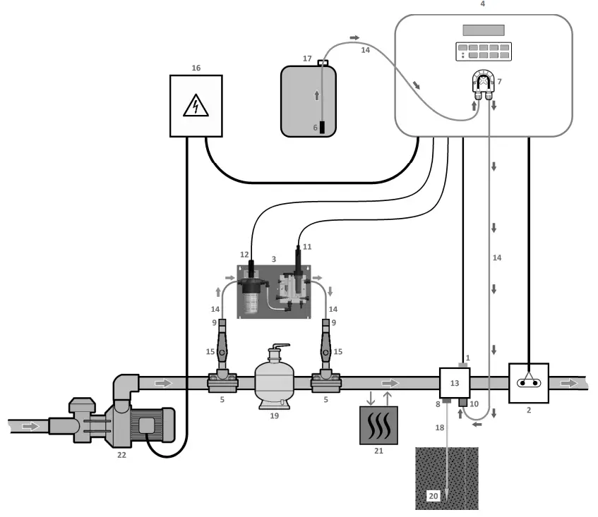
| 1 : Salt/temperature/low water sensor (optiona) 2 : Cell 3 : Measuring chamber 4 : Electronics unit 5 : Saddle 6 : Filter with ballast 7 : Peristaltic pump 8 : Pool Terre (optional) | 9 : Fitting 10 : Injection connector 11 : Amperometric probe 12 : pH probe 13 : Bracket 14 : Semi-flexible tubing 15 : Valve | ELEMENTS NOT SUPPLIED : 16 : Electrical power supply 17 : pH corrector container 18 : Copper cable 19 : Filter 20 : Ground rod 21 : Heat pump 22 : Filtration pump |
ELECTRONICS UNIT
2.1. First commissioning
![]() BEFORE FIRST START UP, carefully read the manual supplied with the amperometric probe. This manual contains instructions that are essential for successful start up and optimal operation of the equipment. It is imperative and rigorous to follow and comply with all of this manual.
BEFORE FIRST START UP, carefully read the manual supplied with the amperometric probe. This manual contains instructions that are essential for successful start up and optimal operation of the equipment. It is imperative and rigorous to follow and comply with all of this manual.
When first connecting the electronics unit to a power supply :
- Carry out the programming below.
Successive
menusPossible settings Navigation Languages
ENGLISH•Francais
•English
•Deutsch
•Espaiol
•Italiano
•Nederlander
•PortuguesFor each menu, select a setting with the 
 buttons, then confirm with the OK button.
Volume somz From 10 to 200 m3, in increments of 10 m3 Date
01/01/01Day / Month / Year Time xx:xx Hour / Minute Display
In line•In line
•Dashboard - Some successive safety mechanisms are displayed.
2.2. LEDsColour Status Possible meanings Green Continuously on Production in progress Red Continuously on •Electronics unit powered off
•Wintering mode on
•Alert activatedFlashing Alarm activated 2.3. Screen
2.3.1. OverviewDisplay Possible meanings Fixed • Read-only information
• Confirmed information
• Alert activatedFlashing • Automatic operation in progress
• Information awaiting confirmation
• Alarm activated2.3.2. Default display
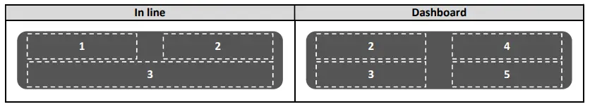
Overview Meaning 1 2 3 4 5 PROD OFF Electrolytic cell put out of service (operating mode set to “OFF”) OFF CL. Electrolytic cell operating mode
4 The point on the far right appears when production is running (additional indicator on the green LED)PROD. In progress Polarisation of amperometric probe in progress Cover Closed cover Ext External command not actuated x. X PPM. Free chlorine level
→ The point on the far right only appears on the dashboard when production is running (additional indicator on the green LED)xxx%. Production setpoint
→ The point on the far right only appears on the dashboard when production is running (additional indicator on the green LED)Boost XXh Boost mode activated Bo kkh. Boost mode activated
→ The point on the far right appears when production is running (additional indicator on the green LED)PH X.X Measuring the pH PH x.x PH OFF pH regulation deactivated OFF X.Xg’L Salt levels xx.xmc Water temperature 2.4. Keypad
COMMAND KEY
(depending on model)FUNCTION  MENU
MENU• Switching on the electronics unit.
→ A few minutes after switching on, production and pH regulation start automatically,
provided that these functions are not deactivated and certain alarms are not activated.
• Switching off the electronic box (press and hold), provided that no alarm or alert isactivated. → When switching off, the screen and the green LED turn off while the red LED comes on.
• Access the menus.BOOST Activation of Boost mode for a period of 24 hours (with a switch-on delay of a few moments). TT • Water temperature display for a few seconds (only if the default display is set to « Online display »).
• Direct access to the menu « settings – Adjustment Temp. » (press and hold).SALT • Salt level display for a few seconds (only if the default display is set to 0 Online display »).
• Direct access to the menu « settings – Salt calibration » (press and hold).pH Direct access to the menu « PH regulation – Calibration » (press and hold). Selecting a value or data element. 
• Cancelling a command.
• Back to the previous (sub)menu.
• Stopping Boost mode.
• Dismissing an alarm or an alert (press or press and hold, depending on the alarm or the alert).OK 
• Command confirmation.
• Entering a (sub)menu.
• Dismissing an alarm or an alert (press or press and hold, depending on the alarm or the alert).2.5. Menu navigation
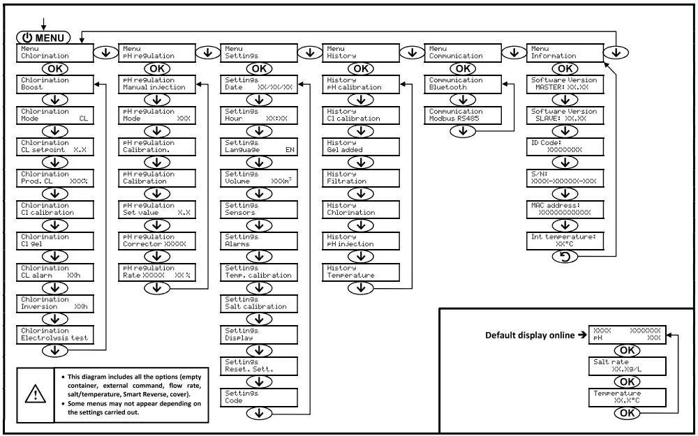
2.6. Features
2.6.1. Selecting the display languageMenu Possible settings Default setting Settings Languages EN Français English Deutsch Español Italiano Nederlander Portugués Français
2.6.2. Setting the date and timeMenu Possible settings Default setting Settings
Date XX/XX/XXDay / Month / Year 1/1/01 Settings
Hour XX:XXHour / Minute random 2.6.3. Selecting the default display
Menu Possible settings Default setting Settings Display •Online
•DashboardOnline Setting Settings viewable by default Electrolytic cell
operating modeFree chlorine
level (1)
orMeasuring
the pHSalt levels Water
temperatureproduction
setpoint (2)Online Dashboard (1) If the chlorinator operating mode is set to “CL”.
(2) If the chlorinator operating mode is set to “%”.
2.6.4. Specification of the volume of the poolMenu Possible settings Default setting settingz i
Volume xxxviFrom 10 to 200 m3, in increments of 10 m3 SO r-ry 2.6.5. Specification of the pH corrector type
Menu Possible settings Meaning Default setting regulation
Corrector XXXXXAcid pH- p Acidic Base pH+ 2.6.6. Specification of the concentration of the pH corrector
Menu Possible settings Default setting pH
Rate XXXXregulati X on X X %From 5 to 55 %, in steps of 1 % 37% 2.6.7. Selecting the chlorinator operating mode
Menu Possible
settingsMeanin g Indicator viewable
on the display by defaultDefault
settingChlorination
Mode CLCL Production control with the
amperometric probe, according to the CL setpoint and the production setpoint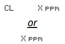
CL % Continual production, at the
production setpoint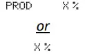
OFF Deactivation of the electrolytic cell 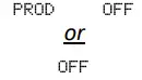
→ Depending on the setting carried out, some menus may not appear.
2.6.8. Memorisation of the last refill/change of electrolyte gel
→ The electrolyte gel relates to the amperometric probe (see the manual supplied with the probe).
→ The menu below only appears if the operating mode of the chlorinator is set to “CL”.Menu Sub-menu Principle Confirmation Chlorination Cl gel Cl gel
Gel addedDate of last refill/change
Date of last confirmationPress twice on OK :
the message 0 Gel Addition Successful » is displayed.2.6.9. Programming the « Info Gel CL » alert
→ The « Info Gel CL » alert is a reminder to fill/change the electrolytic gel on the same day this alert is activated.
→ The menu below only appears if the operating mode of the chlorinator is set to “CL”.Menu Sub-menu Activation delay after the last refill/change of electrolyte gel Possible settings Default setting Chlorination Cl gel Cl gel Info From 30 to 180 days, in 30-day increments 90 days 2.6.10. Setting the « CL regulation » alarm
→ The « CL regulation » alarm is triggered when the free chlorine level is out of tolerance (± 2 ppm exceeded from the CL setpoint during 48 hours – Default setting).
→ The menu below only appears if the operating mode of the chlorinator is set to “CL”.Menu Activation delay after fault detection Possible settings Default setting Chlorination
CL alarm XXhFrom 12 to 96 hrs, in increments of 12 hrs 48 hrs 2.6.11. Sensor settings
Menu Sensor Setting Possible settings Default setting Settings Sensors Cover/Ext cmd Mode • Cover
• OFF
• Cmd extCover Type • NO
• NCNO Flow/pH container Mode • OFF
• pH container
• FlowOFF Type • NO
• NCNO Salt – • ON
• OFFON Temperature – • ON
• OFFON Cmd ext : external command.
PH container : empty container sensor.
Type : this parameter does not appear if the corresponding mode is set to OFF.
ON : sensor activated.
OFF : sensor disabled.
NO : switch normally open.
NC : switch normally closed.Sensor activated Configuration Specific display Production pH regulation Shutter Open cover – Maintained Maintained Closed cover Shutter Divided by 5* External command Command activated – Maintained Command not activated Ext Stopped Flow Sufficient flow – Maintained Zero flow Plarm Flow Stopped Stopped Empty container Empty container Plarn Empty pH container Maintained Container not empty – Maintained Maintained Salt Salt level less than 2.5 g/L
(or 1.5 g/L if Low Salt equipment)Alarm Low salt Stopped Salt level equal to or greater than 2.5 g/L
(or 1.5 g/L if Low Salt equipment)– Maintained Temperature Water temperature below 15°C InfWi nteroing Stopped Water temperature equal to or higher than 15°C – Maintained * To modify this value, contact a professional.
2.6.12. Calibration of the water temperature measurement
→ If the temperature sensor is disabled, the menu below does not appear.Menu Possible settings Default setting Settings
Salt calibrationFrom 0.1 to 8 g/L, in increments of 0.1 g/L Current measurement 2.6.14. Calibration of the pH measurement
Menu Possible settings Default setting PH regulation Calibration From 6.5 to 7.5, in increments of 0.1 Current measurement 2.6.15. Calibration of the free chlorine rate measurement
→ The menu below only appears if the operating mode of the chlorinator is set to “CL”.Menu Possible settings Default setting Chlorination Cl calibration From 0.1 to 5 ppm, in increments of 0.1 ppm Current measurement 2.6.16. Adjustment of the current inversion supplying power to the cell
The power supply inversion aims to prevent scale deposits on the cell. It is imperative to correctly adjust this inversion, in order to maintain the good functioning of the cell in the long term.Menu Setting Possible settings Setting to be determined Default setting Chlorination Inversion XXh Mode • Auto
• ManualAccording to the description below Auto Inversion time From 2 to 24 hrs,
in 1 hr incrementsAccordin to the table below 6 hrs Water hardness • Soft (from 0 to 15°f)
• Mixed (from 15 to 25°f)
• Hard (above 257)According to actual value Mixed Auto : The inversion time is set automatically according to predefined parameters, including the specified water hardness.
Manual : The inversion time is set manually according to the specified value.
Inversion time : This parameter does not appear if the Mode is set to Auto.
Water hardness : This parameter does not appear if the Mode is set to Manual.Water hardness (°f) 0 to 5 5 to 12 12 to 20 20 to 40 40 to 60 > 60 Inversion time (h) 16 10 8 6 4 2 2.6.17. Setting the production setpoint
Electrolytic cell
operating modeMenu Specific instructions Possible settings Default
settingCL Chlorination Prod. CL XXX4 – From 10 to 100 %, in steps of 1 % 100% % Default display Directly select a value using the buttons (no confirmation required)OFF (i.e. 0 %),
then from 10 to 100 %,
in increments of 1 %2.6.18. Setting the pH setpoint
Menu Possible settings Default setting PH regulation
Set value X.XFrom 6.8 to 7.6, in increments of 0.1 7.
2.6.19. Setting the CL setpoint
→ The menu below only appears if the operating mode of the chlorinator is set to “CL”.Menu Possible settings Default setting Chlorination
CL setpoint X.XFrom 0.1 to 5 ppm, in increments of 0.1 ppm 1 ppm
2.6.20. Boost mode
Boost mode :
– can be used when chlorine is urgently needed.
– sets the production setpoint up to 125 %, for a fixed period.
– can be manually stopped at any time.![]() Boost mode cannot replace a conventional shock treatment in cases of water not fit for bathing.
Boost mode cannot replace a conventional shock treatment in cases of water not fit for bathing.
- It is impossible to start Boost mode if :
– An alarm has been activated. (After having resolved and dismissed this alarm, wait a few moments in order to be
able to activate the Boost mode.)
– The operating mode of the electrolytic cell is set to “OFF”. - If the Boost mode is restarted manually while it is already running, the Boost mode resets for the duration displayed.
- Boost mode continues after powering off the electronics unit.
- When the Boost mode is manually terminated or stopped, production continues according to the initial setpoint.
Operation with a cover sensor :
- It is impossible to start Boost mode when the cover is closed.
- If the cover closes with Boost mode activated, Boost mode stops instantly.
| Menu | Possible settings | Default setting | Switching on | Switching off |
| Chlorination Boost | • 12 hrs • 24 hrs | 24 hrs | Automatic, as soon as the selected setting is confirmed, with a delay of a few moments | Press on |
2.6.21. pH probe calibration
→ The original pH probe is already calibrated. It is therefore not necessary to carry out calibration of the pH probe when putting the equipment into service for the first time.
![]() However, it is imperative to carry out a calibration at the beginning of each season when returning to service, and after each probe replacement.
However, it is imperative to carry out a calibration at the beginning of each season when returning to service, and after each probe replacement.
- Open the pH 7 and pH 10 calibration solutions (use only single-use calibration solutions).
- Turn off the filtration (and therefore the electronics unit).
- If the probe is already installed :
a) Take the probe out of the measuring chamber, without disconnecting the probe.
b) Close the housing of the probe in the measuring chamber using the cap provided for this purpose.
If the probe is not already installed :
Connect the probe to the electronics unit. - Turn on the electronics unit.
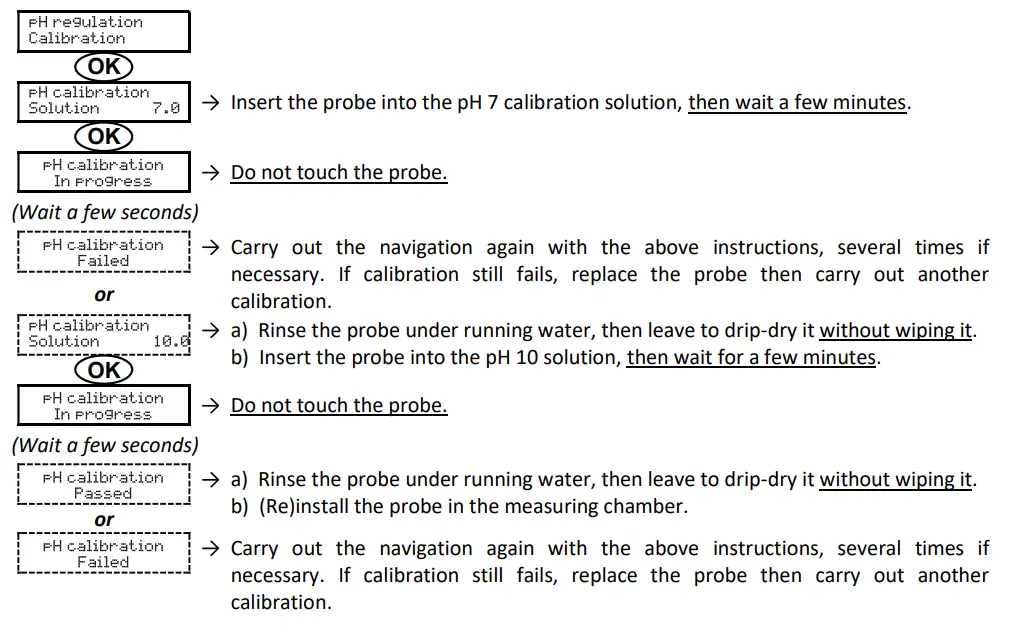
- Go to the « » menu.
- Navigate through the menus following the below instructions :
2.6.22. Activation/deactivation of pH regulation
| Menu | Possible settings | Default setting |
| pH regulation Mode XXX | • ON (to activate) • OFF (to disable) | ON |
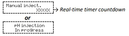
2.6.23. Manual injection
| Menu | Functions | Possible settings | Setting by default | Instructions |
| * regulation Manual inject. | •Priming of the peristaltic pump and filling of semi- rigid i es p p . – pH corrector injection •Means of checking the correct operation of the peristaltic pump | From 30 s to 10 min, in 30 s increments | 1 min | • To start injecting : Confirm the selected setting. (The peristaltic pump is running, and the timer countdown is displayed in real time.) • To pause, and to restart the injection : Press on OK. • To stop the injection : Press on |
2.6.24. Bluetooth communication
| Menu | Setting | Function | Possible settings | Default setting |
| CommunicationBluetooth | Mode | Activation/deactivation of Bluetooth communication | • ON (to activate) • OFF (to disable) | ON |
| Pairing* | • Detection of connectible devices near the electronics unit (within 60 seconds) • Networking of the electronics unit and connected devices | _ | ||
| Reset* | Removal of the network connecting the electronics unit to the connected devices | |||
* These settings do not appear if the mode is set to OFF.
→ During a (non-automatic) update of the electronic box software carried out via Bluetooth :
– The 2 LEDs (red and green) flash alternately.
– The message « Download – In progress » is displayed.
2.6.25. Chlorination test
→ This test is for use by professionals when carrying out maintenance operations on the equipment.
| Menu | Navigation |
| Chlorination Electroysis test | 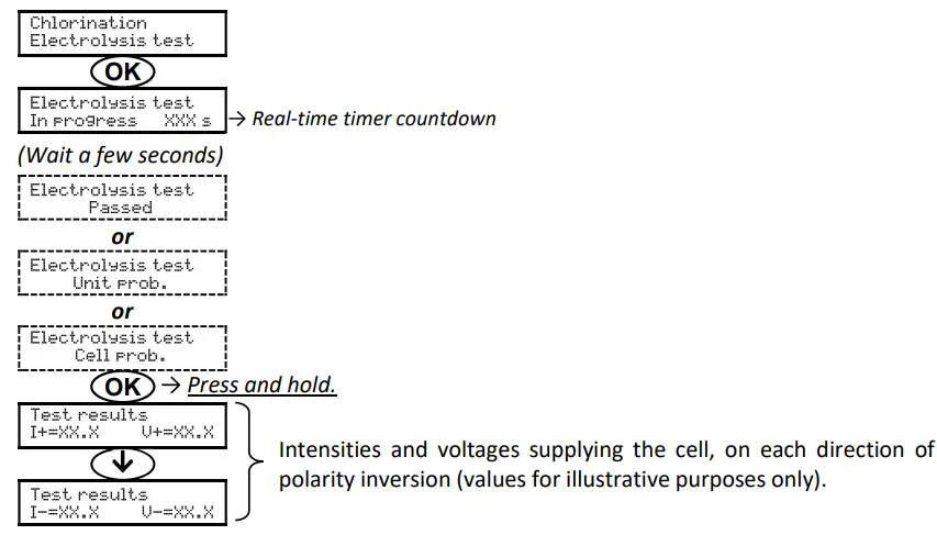 |
2.6.26. Settings reset
| Menu | Important warning |
| Settings Reset. Sett. |
2.7. Safety
2.7.1. Wintering mode
- The wintering mode is activated by default.
- When wintering mode is activated, wintering mode is automatically switched on and off.
- When wintering mode is on, this is instantly displayed on the screen.
- Wintering mode cannot be manually stopped when it is running.
| MESSAGE DISPLAYED | IMMEDIATE AUTOMATIC STOP | POSSIBLE CAUSE | CHECKS AND REMEDIES | OPTION TO DEACTIVATE VIA THE MENU v setting=. – Plarpl, )) | |
| Production | pH regulation | ||||
| Info Wintering | Yes | No | Water temperature below 15°C | Check that the heat pump : | Yes |
| – is set correctly. – works correctly. | |||||
| Incorrect or defective electrical connection of the temperature sensor | Check : | ||||
| – the connection of the temperature sensor to the electronics unit. – the condition of the temperature sensor cable. | |||||
| Defective temperature sensor | Change the temperature sensor. | ||||
2.7.2. Alarms and alerts
| AUTOMATIC OPERATION(S) UPON ACTIVATION | DISMISSAL* | |||
| DEFAULT CONFIGURATION | Message displayed | Immediate stop of production and/or pH regulation | ||
| ALARMS | Activated | Alam (…) | Yes | Press the OK or button (press or press and hold, depending whether it is alarm or alert). |
| ALERTS | Info (…) | No | ||
* The corresponding alarm or alert is maintained while the detected fault remains in place, and the corresponding message reappears a few moments after dismissal.
| MESSAGE DISPLAYED/ FAULT DETECTED | IMMEDIATE AUTOMATIC STOP | POSSIBLE CAUSE | CHECKS AND REMEDIES | OPTION TO DEACTIVATE VIA THE MENU « Seturrs. – alarms o | |
| Production | pH regulation | ||||
| Alarm cl calibration | Yes | No | Unadjusted free chlorine rate measurement | Carrying out an adjustment of the free chlorine rate measurement. | Yes |
| Alarm Emetv pH container | No | Yes | pH corrector container empty | Replace the pH corrector container. | Yes |
| Al pr:„ | Yes | No | Cell problem | •Check that : | No |
| – the cell is not scaled. – the electrical connections to the terminals of the cell are sufficiently tight and not oxidised. – the cell’s power cable is in good condition. – the cell’s power cable connector is correctly connected to the electronics unit. •Check (and adjust if necessary) the setting of the current inversion supplying power to the cell. •As a last resort, replace the cell. | |||||
| Insufficient salt rate | •Check the salt level manually with a recent test kit. •Top up with salt if necessary, so as to obtain a salt level of 5 kg/m3 (or 2.5 kg/m3 for Low Salt equipment). | ||||
| Electronics unit power board problem | Contact a professional. | ||||
| MESSAGE DISPLAYED / FAULT DETECTED | IMMEDIATE AUTOMATIC STOP | POSSIBLE CAUSE | CHECKS AND REMEDIES | OPTION TO DEACTIVATE VIA THE MENU u Settings – Alarms 0 | |
| Production | pH regulation | ||||
| .-,i , | Yes | Yes | Insufficient water flow | Check that : | No |
| – the flow sensor is properly connected to the electronics unit. – the flow sensor is activated (see sensor settings). – the valves on the filtration circuit are open. – the filtration pump is working correctly. – the filtration circuit is not blocked. – there is enough water in the pool. | |||||
| Yes | No | Loss of communication between the control board and the power board of the electronics unit | Contact a professional. | No | |
| 4 | Yes | No | Incorrect or defective electrical connection of the amperometric probe | Check : | No |
| – connection of the amperometric probe to the electronics unit. – the condition of the amperometric probe cable. – internal wiring to the amperometric probe. – the state of the terminal block internal to the amperometric probe. | |||||
| Amperometric probe defective or at the end of Its life | Change the amperometric probe. | ||||
| MESSAGE DISPLAYED / FAULT DETECTED | IMMEDIATE AUTOMATIC STOP | PO5511311 CAUSE | CHECKS AND REMEDIES | OPTION TO DEACTIVATE VIA THE MENU » | |
| Production | pH regulation | ||||
| Cr | No | Yes | Series of 5 unsuccessful attempts to correct the pH | •Ensure the pH corrector container is not empty. •Check the condition of | Yes |
| the • | |||||
| – filter with ballast. – semi-rigid pipes. – peristaltic pump. – injection connector. •Carry out a manual injection. Check that : | |||||
| – the peristaltic pump is working properly. – the pH corrector is injected correctly. •Check the settings in the « pH regulation – SetPoint », a PH regulation – Corrector » and « Settings – Volume » menus. •Carry out a calibration of the pH probe. | |||||
| Alan, Low water | Yes | Yes | Insufficient quantity of water | •Check that : | Yes |
| – the filtration pump is working correctly. – the pipe at the level of the salt sensor is completely filled with water. •Top up the water if necessary. | |||||
| Zero salt level | •Check the salt level manually with a recent test kit. •Top up with salt if necessary, so as to obtain a salt level of 5 kg/m3 (or 2.5 kg/m3 for Low Salt equipment). | ||||
| MESSAGE DISPLAYED/ FAULT DETECTED | IMMEDIATE AUTOMATIC STOP | POSSIBLE CAUSE | CHECKS AND REMEDIES | OPTION TO DEACTIVATE VIA THE MENU « Settings – Alarms • | |
| Production | pH regulation | ||||
| Alarm CL regulation | Yes | No | Free chlorine rate out of tolerance (excess of ± 2 ppm compared to the CL setpoint during 48 hours – default setting) | •Carry out :, | Yes |
| – an electrolysis test. – an adjustment of the free chlorine rate measurement. •Check (and adjust if necessary) the setting of the CL setpoint. •Set the production setpoint to 100 %. | |||||
| Alarm Low salt | Yes | No | Salt level less than 2.5 g/L (or 1.5 g/L if Low Salt equipment) | •Check the salt level manually with a recent test kit. •Top up with salt if necessary, so as to obtain a salt level of 5 kg/m3 (or 2.5 kg/m3 for Low Salt equipment). | Yes |
| Insufficient quantity of water | •Check that : | ||||
| – the filtration pump is working correctly. – the pipe at the level of the salt sensor is completely filled with water. •Top up the water if necessary. | |||||
| into pH calibration | No | No | pH probe incorrectly calibrated | Carry out a calibration of the pH probe. | Yes |
| Into Cl get | No | No | Electrolyte gel of the amperometric probe absent or expired | Fill up/change the electrolyte gel. | Yes |
| Non-memorised electrolytic gel refill/change | Memorise the last refill/change of electrolyte gel. | ||||
2.7.3. Important precautions regarding the peristaltic pump
This chapter is applicable if the electronics unit is fitted with a cover hiding the peristaltic pump.![]() When one of the 2 messages below is displayed, the peristaltic pump is running. IN THIS CASE, DO NOT REMOVE THE COVER OF THE ELECTRONICS UNIT COVERING THE PERISTALTIC PUMP.
When one of the 2 messages below is displayed, the peristaltic pump is running. IN THIS CASE, DO NOT REMOVE THE COVER OF THE ELECTRONICS UNIT COVERING THE PERISTALTIC PUMP.
→ If case of doubt about the correct functioning of the peristaltic pump :
- Switch off the electronics unit.
- Removethe cover of the electronics unit which covers the peristaltic pump.
- Remove the internal pipe from the peristaltic pump, without removing the semi-rigid pipes connected to it.
- Check the condition of the peristaltic pump and internal pipes.
- Turn on the electronics unit.
- Carry out a manual (vacuum) injection.
- Check that the peristaltic pump is running correctly.
2.8. Data history
| Menu | Sub-menu | Content |
| History pH calibration | _ | Date of the last pH probe calibration |
| History Cl calibration | – | Date of the last adjustment of the free chlorine rate measurement |
| HistoryGel added | _ | Date of the last refill/change of electrolyte gel |
| History Filtration | Filtration Time D-1 | Duration of filtration pump operation the previous day |
| Filtration Average time W-1 | Average daily operating time of the filtration pump the previous week | |
| Filtration Average time M-1 | Average daily operating time of the filtration pump the preceding month | |
| History Chlorination | Chlorination Time D-1 | Duration of chlorine production the previous day |
| Chlorination Average time 61-1 | Average daily chlorine production time in the previous week | |
| Chlorination Average time M-1 | Average daily chlorine production time in the previous month | |
| Chlorination Total | Cumulative duration of chlorine production since the first start up of the electronics unit | |
| Chlorination Cell life | Remaining cell life (estimate in %) | |
| History PH injection | PH injection Time D-1 | Duration of peristaltic pump operation the previous day |
| PH injection Average time W-1 | Average daily operating time of the peristaltic pump the previous week | |
| PH injection Average time M-1 | Average daily operating time of the peristaltic pump the preceding month | |
| PH injection Total | Cumulative duration of peristaltic pump operation since the first start up of the electronics unit | |
| History Temperature | Temperature Temp.D-1 | Average water temperature the previous day |
| Temperature Temp. W-1 | Average water temperature for the previous week | |
| Temperature Temp. ri-i | Average water temperature for the previous month |
2.9. Further information
| Menu | Meaning |
| Software Version MASTER: XX.XX | Control boardprogram |
| Software Version SLAVE: XX.XX | Power cardprogram |
| ID Code: xxxxxxxx | Configuration code |
| S/N: xxxx-xxxxxx-xxx | Serial number |
| MAC address: xxxxxxxxxxxx | MAC address for Bluetooth connection |
| Int temperature: xx.c | Internal temperature |
GUARANTEE
Before contacting your dealer, please have the following to hand :
– your purchase invoice. – the serial no. of the electronics unit.
– the installation date of the equipment.
– the parameters of your pool (salinity, pH, chlorine levels, water temperature, stabilizer level, pool volume, daily filtration time, etc.).
Every effort and all our technical experience has gone into designing this equipment. It has been subjected to quality controls. If, despite all the attention and expertise involved in its manufacture, you need to make use of our guarantee, it only applies to free replacement of the equipment’s defective parts (excluding shipping costs in both directions).
Guarantee period (proven by date of invoice)
Electronics unit : 2 years. Cell : – 1 year minimum outside the European Union (excluding warranty extension).
– 2 year minimum in the European Union (excluding warranty extension).
Probes : depending on model. Repairs and spare parts : 3 months.
The periods indicated above correspond to standard guarantees. However, these can vary depending on the country of installation and the distribution network.
Scope of the guarantee
The guarantee covers all parts, with the exception of wearing parts that must be replaced regularly.
The equipment is guaranteed against all manufacturing defects within the strict limitations of normal use.
After-sales services
All repairs will be carried out in the workshop.
Shipping costs in both directions are at the user’s own expense.
Any downtime and loss of use of a device in the event of repairs shall not give rise to any claim for compensation.
In all cases, the equipment is always sent at the user’s own risk.
Before taking delivery, the user must ensure that it is in perfect condition and, if necessary, write down any reservations on the shipping note of the carrier.
Confirm with the carrier within 72 hours by recorded letter with acknowledgement of receipt.
Replacement under guarantee shall in no case extend the original guarantee period.
Guarantee application limit
In order to improve the quality of their products, the manufacturer reserves the right to modify the characteristics of the products at any time without notice. This documentation is provided for information purposes only and is not contractually binding with respect to third parties. The manufacturer’s guarantee, which covers manufacturing defects, should not be confused with the operations described in this documentation. Installation, maintenance and, more generally, any servicing of the manufacturer’s products should only be performed by professionals. This work must also be carried out in accordance with the current standards in the country of installation at the time of installation. The use of any parts other than original parts voids the guarantee ipso facto for the entire equipment.
The following are excluded from the guarantee :
– Equipment and labour provided by third parties in installing the device.
– Damage caused by installation not in compliance with the instructions.
– Problems caused by modifications, accidents, misuse, negligence of professionals or end users, unauthorised repairs, fire, floods, lightning, freezing, armed conflict or any other force-majeure events.
Any equipment damaged due to non-compliance with the instructions regarding safety, installation, use and maintenance contained in this documentation will not be covered by the guarantee. Every year, we make improvements to our products and software. These new versions are compatible with previous models. The new versions of hardware and software cannot be added to earlier models under the guarantee.
Implementation of the guarantee
For more information regarding this guarantee, contact your dealer or our After-Sales Service. All requests must be accompanied by a copy of the purchase invoice.
Legislation and disputes
This guarantee is subject to French law and all European directives or international treaties in force at the time of the claim, applicable in France. In case of disputes concerning its interpretation or execution, the High Court of Montpellier (France) shall have exclusive jurisdiction.